Page is loading ...

QR CODE
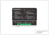
UNIVERSAL KEYPAD FAMILY
21 3
4
3
4
21
75.5892.04 KEYPADS 20201007 Page 1 of 8
Stand-alone access control keypads
ENGLISH
DESCRIPTION
Visit website for
available languages of
this document.
1. Door LED
2. Mode LED
3. Matrix keypad
4. Case screw
(bottom of case)
10KEYPADU 10KEYPADUSL
(slimline)
TECHNICAL SPECIFICATIONS
Supply voltage: 12 – 24 VAC/VDC
WARNING: Product will be damaged and warranty will be voided if
supply voltage exceeds 30VDC or 24VAC.
This product shall not be used with a BEA part number 1024VAC
transformer or any standard, non-regulated 24VAC transformer as the
measured voltage exceeds 24 VAC.
Standby current: ≤ 30 mA
Working current: ≤ 160 mA
Max user codes: 1010 ( zone 1: 1000 users, zone 2: 10 users)
Relock time: 0 – 99 seconds
Output: 2 relays (free of potential change-over contact)
Max. contact voltage: 42 VAC/VDC
Max. contact current: 1 A (resistive)
Max. switching power: 30 W (VDC) / 48 VA (VAC)
Cable length: 3 ft
Operating temperature: -22 – 158 °F
Operating humidity: 0 – 95% (non-condensing)
IP rating: IP66 (waterproof and dustproof)
Dimension: 10KEYPADU: 3.0” (W) x 4.7” (H) x 0.9” (D) – (76 mm x 120 mm x 22 mm)
10KEYPADUSL: 1.7” (W) x 5.9” (H) x 0.95” (D) – (44 mm x 150 mm x 24 mm)
Certification: CE, RoHS
Backlight: Blue keypad illumination
Specifications are subject to change without prior notice.
All values measured in specific conditions.

1
3
2
*
*
Page 2 of 8 75.5892.04 KEYPADS 20201007
READ BEFORE BEGINNING INSTALLATION/PROGRAMMING/SET-UP
Shut off all power going to header before attempting any wiring procedures.
Maintain a clean and safe environment when working in public areas.
Always check placement of all wiring before powering up to ensure that moving door parts will
not catch any wires and cause damage to equipment.
Ensure compliance with all applicable safety standards (i.e. ANSI A156.10) upon completion of
installation.
!
CAUTION
PRECAUTIONS
MOUNTING
INSTALLATION TIPS
Using the supplied hex key, remove the
backcase screw from the keypad bottom.
Mount backcase on the wall with provided screws.
Make sure to pull keypad cable through the center
hole.
Keep keypad horizontal to the floor.
Use the drilling template and drill required holes.
For surface mounting, drill the 4 corner holes in the image.
For single-gang box mounting, drill the 2 holes marked with
an asterisk in the image.
NOTE: Do not damage the tamper sensor.
• Handle the equipment with care.
• Add threadlocker to all screws before
installing.
• Firmly tighten screws.

75.5892.04 KEYPADS 20201007 Page 3 of 8
PROGRAMMING TIPS
-
+
}
-
+
1 Red (power +)
2 Black (power ground)
3 Brown (door magnet)
4 Orange (zone 1 exit button)
5 Yellow (zone 2 exit button)
6 Green (exit button – COM)
7 White (NO)
8 Pink (COM)
9 Aqua (NC)
10 Blue (NO)
11 Purple (COM)
12 Gray (NC)
8”
0.5W recommended
13 Brown/White (door bell)
14 Black/White (door bell)
Shielding line
Input DC: 12V to 24V
Input AC: 12V to 24V
Shield ground
Zone 1
UNLOCK
(dry)
Zone 2
UNLOCK
(dry)
WIRING
PROGRAMMING
Connect the wires based on the wiring diagram below.
When wiring is complete, mount the keypad to the back cover by using the provided screws.
• If you forget the administration code, turn off the power, press and hold “#” key, and then
turn the power back on. A short beep will be heard and the administration code has been
restored back to 1234.
• If no buttons are pressed within 30 seconds while in “setup” mode, the device will turn
back to normal function automatically. Mode LED turns green.
• If any incorrect key combinations are entered, a continuous beep will be heard.

Page 4 of 8 75.5892.04 KEYPADS 20201007
PROGRAMMING (cont.)
GETTING STARTED
ADMIN CODES
DOOR MODE
ENTER SETUP MODE
Enter the default administration code (1234) twice (i.e. 1234 + 1234) to enter
“setup” mode.
Mode LED will turn red and a long beep will be heard.
Press the “#” key to exit “setup” mode. Mode LED will turn green.
DOOR MODE
MODIFY ADMIN CODE
Enter “setup” mode.
Press the star (*) key and then “3”. Mode LED will flash red.
Enter a new 4-digit number (0000 – 9999) twice to set the new admin code.
Press “#” to exit “setup” mode. Mode LED turns green.
CHANGE LENGTH OF ADMIN CODE
Changing the admin code length will delete all existing user codes.
Changing the admin code length will reset the admin code back to a sequential number (similar to that
in step 1a), consiting of the correct amount of digits (e.g. if the admin code length is changed to 6 digits,
the admin code defaults to “123456”).
Enter “setup” mode.
Press the star (*) key and then “9”. Mode LED will flash red.
Press “0” and then “4”. A short beep will sound. Mode LED will turn red.
Enter the length of the admin code in digits, ranging from “2” to “6” (“2” is the minimum code
length, and “6” is the maximum).
• one beep = admin code length successfully changed
• three beeps = admin code length is equal to existing length
Press “#” to exit “Admin code length setup” mode. Mode LED remains red.
Press “#” again to exit “setup” mode. Mode LED turns green.

75.5892.04 KEYPADS 20201007 Page 5 of 8
PROGRAMMING (cont.)
USER CODES
DOOR MODE
ADD USER CODE TO ZONE 1
(must be different from admin code)
Enter “setup” mode.
Press the star (*) key and then “9”. Mode LED will flash red.
Press “0” and then “2”. A short beep will sound. Mode LED will turn red.
Enter a 3-digit number (000 – 999) to set the electronic location for the zone
1 user code. LED remains red, and a a short beep will sound after entering the
3-digit number.
Enter the new user code. The user code must be the same length as the admin code. A long beep
will sound. User code is successfully added. The new code will replace the existing code stored in the
same location.
Repeat the previous two steps to add more codes.
Press “#” to exit “Add user code to zone 1” mode. Mode LED remains red.
Press “#” again to exit “setup” mode. Mode LED turns green.
NOTE: When zone 1 output relay is activated, the door indicator LED will
turn green.
ADD USER CODE TO ZONE 2
(must be different from admin code and zone 1 user code)
Enter “setup” mode.
Press the star (*) key and then “9”. Mode LED will flash red.
Press “0” and then “3”. A short beep will sound. Mode LED will turn red.
Enter a 2-digit number (00 – 99) to set the electronic location for the zone 2 user
code. LED remains red, and a a short beep will sound after entering the 2-digit
number.
Enter the new user code. The user code must be the same length as the admin code. A long beep
will sound. User code is successfully added. The new code will replace the existing code stored in the
same location.
Repeat the previous two steps to add more codes.
Press “#” to exit “Add user code to zone 2” mode. Mode LED remains red.
Press # again to exit “setup” mode. Mode LED turns green.
NOTE: When zone 2 output relay is activated, the door indicator LED will
turn red.

Page 6 of 8 75.5892.04 KEYPADS 20201007
PROGRAMMING (cont.)
USER CODES (cont.)
DOOR MODE
REMOVE ONE USER CODE
Enter “setup” mode.
Enter the location of the user code to be deleted (three digits). Mode LED will
flash red.
Press the star (*) key twice to delete. Door LED turns green. Mode LED will flash red.
Press “#” twice to end programming. Mode LED turns green.
REMOVE ALL USER CODES
Enter “setup” mode.
Press the star (*) key and then “8”. Mode LED will flash red.
Press “8” twice. A long beep will sound. Mode LED will flash red.
Press “#” again to exit “setup” mode. Mode LED turns green.
UNLOCKING TIMES
DOOR MODE
SET UNLOCKING TIME FOR ZONE 1
Enter “setup” mode.
Press the star (*) key and then “1”. Mode LED will flash red.
Enter a 2-digit number (00 – 99) for the “unlock time” value.
• “00” = sets “unlock time” to toggle mode (“00” to both open and close the door)
• “01” – “99” = “unlock time” in seconds
After entering the “unlock time” number, a long beep will sound and the mode
LED turns red.
Press “#” again to exit “setup” mode. Mode LED turns green.
SET UNLOCKING TIME FOR ZONE 2
Enter “setup” mode.
Press the star (*) key and then “5”. Mode LED will flash red.
Enter a 2-digit number (00 – 99) for the “unlock time” value.
• “00” = sets “unlock time” to toggle mode (“00” to both open and close the door)
• “01” – “99” = “unlock time” in seconds
After entering the “unlock time” number, a long beep will sound and the mode
LED turns red.
Press “#” again to exit “setup” mode. Mode LED turns green.

75.5892.04 KEYPADS 20201007 Page 7 of 8
FACTORY RESTORE
DOOR BELL
DOOR MODE
RESTORE TO FACTORY DEFAULTS
Enter “setup” mode.
Press the star (*) key and then “8”. Mode LED will flash red.
Press “9” twice. A long beep will sound. Mode LED will flash red.
Press “#” again to exit “setup” mode. Mode LED turns green.
PROGRAM A DOOR BELL
Connect an external speaker (8Ω, 0.5w) to brown/white and black/white wires of this device.
Press the star (*) key and the external speaker rings as a door bell.
OPTIONAL PROGRAMMING
TAMPER ALARM
DOOR MODE
TURN ON TAMPER ALARM
To turn on the tamper alarm feature, enter “setup” mode.
Press the star (*) key and then “6”. Mode LED will flash red.
Press “0” and then “2”. A long beep will sound. Mode LED will turn red.
Press “#” again to exit “setup” mode. Mode LED turns green.
TURN OFF TAMPER ALARM
To turn off the tamper alarm, enter “setup” mode.
Press the star (*) key and then “6”. Mode LED will flash red.
Press “0” and then “1”. A long beep will sound. Mode LED will turn red.
Press “#” again to exit “setup” mode. Mode LED turns green.
This feature allows a built-in buzzer to activate if the keypad is removed from the wall.
The alarm will stop automatically in 60 seconds or if the admin code is entered before the
60-second timeout.
FACTORY DEFAULT: OFF

Page 8 of 8 75.5892.04 KEYPADS 20201007
BEA Inc., the sensor manufacturer, cannot be held responsible for incorrect installations or inappropriate adjustments or the sensor/device; therefore, BEA Inc. does not
guarantee any use of the sensor outside its intended purpose.
BEA Inc. strongly recommends that installation and service technicians be AAADM-certifi ed for pedestrian doors, IDA-certifi ed for doors/gates, and factory-trained for
the type of door/gate system.
Installers and service personnel are responsible for executing a risk assessment following each installation/service performed, ensuring that the sensor system installation
and/or device is compliant with local, national, and international regulations, codes, and standards.
Once installation or service work is complete, a safety inspection of the system should be performed and documented per the manufacturers recommendations, or
industry guidelines. Examples of compliance may apply to ANSI 156.10, ANSI 156.19, ANSI/DASMA 102, ANSI/DASMA 107, UL294, International Building Code.
BEA, INC. INSTALLATION/SERVICE COMPLIANCE EXPECTATIONS
Tech Support & Customer Service: 1-800-523-2462
General Tech Questions: [email protected] | Tech Docs: www.BEAsensors.com
©BEA | Original Instructions | PLEASE KEEP FOR FURTHER USE - DESIGNED FOR COLOR PRINTING
USER OPERATION
Simply enter the user code provided to you.
If 3 invalid consecutive keyboard input entries occur, the keypad will be disabled for 60 seconds.
/