
Installatie instructies
Installation instructions
Installationsvorschriften
Instructions d’installation
Instrucciones de instalación
Istruzioni per l’installazione
NEDERLANDS 2
ENGLISH 6
DEUTSCH 10
FRANÇAIS 14
ESPAÑOL 18
ITALIANO 22
Copyright © 2014 Vetus b.v. Schiedam Holland
‘Light Series’
Kabelbesturingsset
Cable steering set
Seilzuglenkungssatz
Kit de direction
Cable de dirección
Kit timoneria meccanica
LCS
Page is loading ...
Page is loading ...
Page is loading ...
Page is loading ...

6 VQ12060_A
Light Series Cable Steering
Note!
This instruction contains important safety information and must
be forwarded to the boat owner.
1 Introduction
With this rotary cable steering system you steer the boat by control-
ling the outboard motor.
A complete cable steering systems consists of a helm unit, a steering
cable and a kit to connect the cable tot the outboard motor.
You can choose from 4 dierent sets:
Splashwell mount (SSPLASH), Transom mount with short bracket
(STRANS), Transom mount with long bracket (STRANSL) or Engine
mount (SLINK).
Incorrect installation or usage of foreign parts may cause opera-
tion failure which can result damage or injury to boat or person.
Vetus will not be responsible for any cases that are not in conform-
ity to the conditions of this instruction.
Please mind some warnings as mentioned below:
cautioN
Indicates that the usage procedures, actions etc. concerned can re-
sult in serious damage to or destruction of the steering system. Some
CAUTION indications also advise that a potential danger exists that
can lead to serious injury or death.
Note
Emphasises important procedures, circumstances etc.
cautioN
1 Read this manual carefully before installation.
2 Do not substitute parts without Vetus conrmation.
3 Every condition in this document must be fullled.
4 Do not disassemble any parts of the product.
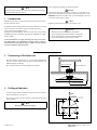
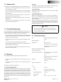
min. 100 mm
min. 200 mm
min. 300 mm
(4”)
(8”)
(12”)
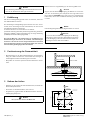
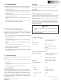
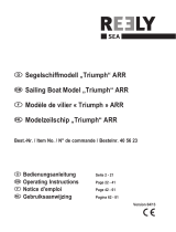
2 Positioning of the helm unit
• Take the clearance requirements in account when determining
the exact position of the helm unit. This to avoid interference &
diculty during assembling.
• Also check the clearance for steering wheel’s operation.
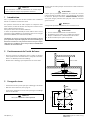
3 Drilling of the holes
• Locate the holes on the dash after the clearance has been checked.
• Use the drill pattern, see page 33.
• If necessary, enlarge the centre hole to accommodate the steering
helm assembly.
Note
One (1) hole must be top centre!
TO P
ø 5 (0.2”)
ø 6.8 (0.26”)
ø 64 (2.5”)
58 (2.3”)
75.5 (3”)
58 (2.3”)

VQ12060_A 7
Light Series Cable Steering
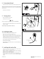
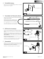
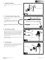
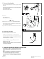
4 Mounting bracket
• Install the mounting bracket; use fasteners as indicated.
1/4-28 UNF x 1 3/8”
7/16”
(1.9 - 2.8 ft.lbf )2.6 - 3.8 Nm
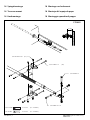
5 Steering cable and spent tube
• Route the steering cable through the boat from helm position to
outboard motor.
The spent tube (1) protects the inner cable
against the surrounding equipment and visa
versa.
• The protective hose (2), for transport purposes
only, can now be removed and discarded.
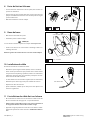
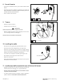
6 Entering cable
• Feed the inner cable through the helm unit while turning the
steering wheel to pull cable end to inside the rotary assembly.
• Check steering direction, making sure that when wheel is
turned to the right, the boat will turn to the right.
• Install spent tube cable cover by slipping it over the cable end.
• Use fasteners as indicated to secure the cable jacket and the spent
tube.
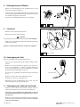
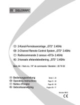
7 Helm unit
• Place the helm through the centre hole. There are multiple holes
for mounting the helm. Which ones you use will depend on your
particular installation location and cable routing.
• Use fasteners as indicated.
1/4-28 UNF x 1 3/8”
7/16”
(1.9 - 2.8 ft.lbf )
2.6 - 3.8 Nm
1/4-28 UNF
7/16”
(3.8 - 5.6 ft.lbf )5.1 - 7.6 Nm
1
2
ENGLISH

8 VQ12060_A
Light Series Cable Steering
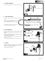
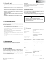
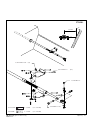
8 Friction brake & bezel
• Insert friction brake to shaft axis, then enforce the friction screw.
Make sure that that the friction brake is positioned in a way that after
installation of the bezel the friction screw can be adjusted through
the bezel’s hole.
• Use fasteners as indicated.
9 Steering wheel
• Place steering wheel on the shaft.
• Install the parts as indicated.
Note
Shown steering wheel is just an example. It is not included.
• Hold the steering wheel while tightening to avoid cable damage
to helm assembly!
Keep the torque range in mind as indicated.
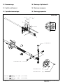
10 Installing the cable
Take note of the following when installing the cable:
- Ensure the correct (total) cable length is used.
- Make as few loops as possible in the cable and make the bend-
ing radius as large as possible (at least 20 cm (8”)). Using a smaller
bending radius will cause excessive wear on the outer cable.
- The cable must be clamped at regular intervals (every 90 cm (3ft)).
- Do not install the cable too close to heat sources.
- Prevent cable from chang.
- After installation, check that the cable can be moved without sig-
nicant resistance.
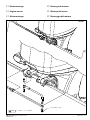
11 Installing cable end on tiller
• Connect end of cable to tiller of motor using one of the connec-
tion kits. See pages 26 - 29 for installation.
• Reinforce transom or bulkhead at location where mounting
brackets are to be installed if required.
• Bring if required the centre position of the steering wheel in ac-
cordance with the centre position of the tiller. Check steering di-
rection.
9/16” (6.3 - 9.4 ft.lbf )8.5 - 12.7 Nm
3/8-16 UNC x 1 1/2”
ø 19 mm (3/4” DIA.) 1: 12
(8”)
min. R 200 mm
PH1 PH2
A
A

VQ12060_A 9
Light Series Cable Steering
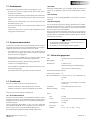
13 Warranty conditions
Failure to comply with the following conditions will cancel any claim
on the warranty and Vetus B.V. will not assume responsibility for any
resulting damage.
- the steering system is installed together with an outboard motor
with a power which exceeds de maximum horsepower rating of
the boat,
- the steering system has been used for an application other than
that stated in the manual,
- the steering system has been improperly tted or installed,
- there is a case of normal wear and tear,
- the conditions concerning operation, maintenance and repair
have not been followed,
- the steering system has been used dierently from what could
normally be expected.
12 Final inspection
Check the following points before test operation:
• The radius of the cable is nowhere less than 200 mm (8“). (See 10
Installing the cable)
• Make sure the direction of rotation of the steering wheel matches
the direction the boat will turn. (See 6 Entering cable)
• Make sure that the end stops of the motor coincide with a cable
travel. (See pg. 31)
• Verify that the friction is set correctly. (See 8 Friction brake)
• Check that all nuts and bolts are tightened to the specied torque.
14 Maintenance
Checking and maintenance should be carried out:
- at least once per month when used in salt water areas
- at least once per 3 months when used in fresh water areas.
Check and service the following:
14.1 Cable output end
Check all metal parts and the cable output end for corrosion. Remove
any old grease from the cable ram and motor swivel connections us-
ing a mild solvent, such as kerosene. Spray the cleaned areas with a
moisture-displacing lubricant such as WD-40 or equivalent and apply
a light coat of good quality marine grease. Do this with the cable ram
fully extended.
14.2 Cable
Check the entire cable conduit for cracks or abrasion of the plastic
cover. Replace the cable if needed.
14.3 Helm
Check all fasteners such as bolts and nuts for tightness.
14.4 Winter storage
In winter storage or used infrequently, clean the cable ram per the
previously mentioned instructions. Cycle the steering several times
when applying lubricant.
If at any time the steering system becomes sti, has an excessive
amount of backlash or shows any change in its operating character-
istics, it is recommended to have the system checked by authorized
dealer.
Note!
- Helm contains no internal eld serviceable parts.
- Any attempt at disassembly of these units will void warranty
of this product.
15 Technical data
Type : Rotary steering system for 1 outboard
Mounting bezel : 90°
Suitable for : Boats up to 5 m (16 ft)
Outboards up to 40 kW (55 HP)
For single station use only
No. of turns steering
wheel H.O. to H.O. : 2.6
Max. wheel diameter : 375 mm (15”), with a max. wheel dish of
125 mm (5”)
or
406 mm (16”), with a wheel dish of less
than 50 mm (2”)
Wheel shaft : 19 mm (
3
/
4
”) dia., 1:12 taper
Weight, helm unit : 1.2 kg (2.6 lbs)
Cable,
- Travel : 230 mm (9”)
- Lengths : 153 to 610 cm (5 to 20 ft)
in steps of 31 cm (1 ft)
- Min. bend radius : 200 mm (8”)
- Max. loop : 360°
- Weight : 1,5 m … 6,1 m ⇒ 1 kg … 2,8 kg
(5 ft … 20 ft ⇒ 2.2 lbs … 6.2 lbs)
ENGLISH
Page is loading ...
Page is loading ...
Page is loading ...
Page is loading ...
Page is loading ...
Page is loading ...
Page is loading ...
Page is loading ...
Page is loading ...
Page is loading ...
Page is loading ...
Page is loading ...
Page is loading ...
Page is loading ...
Page is loading ...
Page is loading ...

26 VQ12060_A
Light Series Cable Steering
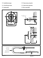
1/4-20 UNC x 1 1/2”
7/16”
2.6 - 3.8 Nm
(6 x)
1/4-20 UNC x 5/16” (6 x)
3/8-24 UNF x 1 1/4”
9/16”
5 - 7.5 Nm
3/8-24 UNF x 2”
1/4-20 UNC
3/8-24 UNF
SSPLASH
pcd 108 (4
1
/
4
”)
ø 90 (3
1
/
2
”)
ø 6 (
1
/
4
”)
102
+0
-13
4”
+0
-1/2”
( )
max. 13 (1/2”)
(1.9 - 2.8 ft.lbf )
(3.7 - 5.5 ft.lbf )
16 Bunmontage
16 Splash well mount
16 Spritzkastenmontage
16 Montage «Splashwell»
16 Montaje mamparo
16 Montaggio pozetta

VQ12060_A 27
Light Series Cable Steering
9/16”
5 - 7.5 Nm
3/8-24 UNF x 1 1/4”
SLINK
(3.7 - 5.5 ft.lbf )
17 Motormontage
17 Engine mount
17 Motormontage
17 Montage du moteur
17 Montaje del motor
17 Montaggio del motore

28 VQ12060_A
Light Series Cable Steering
3/8-24 UNF x 1 1/4”
3/8-24 UNF x 2”
5/16-18 UNC x 3/4” (2 x)
5/16-18 UNC x 3” (4 x)
1/2”
5 - 7.5 Nm
STRANS
9/16”
5 - 7.5 Nm3/8-24 UNF
5/16-18 UNC
51 (2”)
(3.7 - 5.5 ft.lbf )
(3.7 - 5.5 ft.lbf )
18 Spiegelmontage
18 Transom mount
18 Heckmontage
18 Montage sur le dormant
18 Montaje del espejo de popa
18 Montaggio specchio di poppa

VQ12060_A 29
Light Series Cable Steering
5/16-18 UNC x 3/4” (2 x)
5/16-18 UNC x 3” (4 x)
3/8-24 UNF x 1 1/4”
3/8-24 UNF x 2”
1/2”
5 - 7.5 Nm
STRANL
9/16”
5 - 7.5 Nm3/8-24 UNF
5/16-18 UNC
102 (4”)
23º
(3.7 - 5.5 ft.lbf )
(3.7 - 5.5 ft.lbf )

30 VQ12060_A
Light Series Cable Steering
Kabellengte
Cable Length
Kabellänge
Logueur du câble
Longitud del cable
Lunghezza del cavo
STROKE 230 mm (9”)
max. 35 (1
3
/
8
”)
80 (3
1
/
8
”)
121 (4
3
/
4
”)
132 (5
3
/
16
”)
140 (5
1
/
2
”)
ø 19 (
3
/
4
”) 1 : 12
70 (2
3
/
4
”)
70 (2
3
/
4
”)
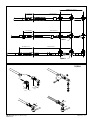
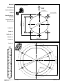
19 Hoofdafmetingen
19 Overall dimensions
19 Hauptmaße
19 Dimensions pricipales
19 Dimensions generales
19 Misure pricipali

VQ12060_A 31
Light Series Cable Steering
100 mm (4”) 380 mm (15”)
75 mm (3”) 380 mm (15”)
140 mm (5
1
/
2
”) 380 mm (15”)
SJOINT
SQBALL
STROKE 230 mm (9”)
1
2
SQBALL
50 mm
(2”)
25 mm
(1”)

32 VQ12060_A
Light Series Cable Steering
Schiedam, 17.03.2014
Ing. P.H. le Pair
Vetus B.V.
Page 1 of 1
Document : DoC_20801 2014-02
Supersedes :
EC Declaration of Conformity
Vetus B.V.
Fokkerstraat 571
3125 BD Schiedam
The Netherlands
LCSKITxx, LCABxx DCI Certificate number: CE-RCD-1405
BOAT EQUIPMENT AND MARINE DIESEL ENGINES
Wij verklaren onder onze volledige verantwoordelijkheid
dat dit product voldoet aan, en in overeenstemming is
met, de volgende normen en richtlijnen:
We declare under our sole responsibility that this product
is in conformity and accordance with the following stand-
ards and directives:
Wir übernehmen vollständige Verantwortung dafür, dass
dieses Produkt den folgenden Normen und Richtlinien
entspricht und deren Anforderungen erfüllt:
Nous déclarons sous notre entière responsabilité que ce
produit est conforme aux normes et directives suivantes :
Declaramos bajo nuestra total responsabilidad que este
producto es conforme a las siguientes normas y directivas:
Dichiariamo sotto la nostra responsabilità che questo prodot-
to è conforme e risponde alle seguenti norme e direttive:
Vi erklærer på vores fulde ansvar, at dette produkt opfylder og
er i overensstemmelse med følgende normer og direktiver:
Vi förklarar under vårt fullständiga ansvar att denna produkt
uppfyller, och är i överensstämmelse med, följande normer
och direktiv:
Vi erklærer under vårt fullstendige ansvar at dette produktet
oppfyller og er i overensstemmelse medfølgende standarder
og direktiver:
Vakuutamme täysin omalla vastuullamme, että tämä tuote
täyttää seuraavien normien ja direktiivien vaatimukset ja yh-
denmukaisuuden:
ISO 9775
94/25/EC as ammended by 2003/44EC

VQ12060_A 33
Light Series Cable Steering
TOP
ø 5 (0.2”)
ø 6.8 (0.26”)
ø 64 (2.5”)
58 (2.3”)
75.5 (3”)
58 (2.3”)
Boormal
Drill pattern
Bohrschablone
Gabarit
Plantilla de per-
foración
Sagoma di tra-
pana natura
Schaal 1:1
Scale 1:1
Maßstab 1:1
Echelle 1:1
Escala 1:1
Scala 1:1
Light Series Cable Steering
pcd 108 (4
1
/
4
”)
ø 90 (3
1
/
2
”)
ø 6 (
1
/
4
”)

34 VQ12060_A
Light Series Cable Steering

VQ12060_A 35
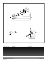
Light Series Cable Steering
LCSKITxx Service onderdelen Service parts
pos. qty part benaming description
1 1 LB90 Montageset 90 graden Mounting set 90 degrees
2 1 SBBALL Set kogelhelften Set of ball halves
3 1 SJOINT Wartelverbindingset Swivel joint set
1
(4x)
(8x)
(8x)
(2x)
2
3
(2x)
(2x)

vetus b.v.
FOKKERSTRAAT 571 - 3125 BD SCHIEDAM - HOLLAND - TEL.: +31 10 4377700
TELEFAX: +31 10 4372673 - 4621286 - E-MAIL: [email protected] - INTERNET: http://www.vetus.com
Printed in the Netherlands
VQ1206_A 2014-03
-
 1
1
-
 2
2
-
 3
3
-
 4
4
-
 5
5
-
 6
6
-
 7
7
-
 8
8
-
 9
9
-
 10
10
-
 11
11
-
 12
12
-
 13
13
-
 14
14
-
 15
15
-
 16
16
-
 17
17
-
 18
18
-
 19
19
-
 20
20
-
 21
21
-
 22
22
-
 23
23
-
 24
24
-
 25
25
-
 26
26
-
 27
27
-
 28
28
-
 29
29
-
 30
30
-
 31
31
-
 32
32
-
 33
33
-
 34
34
-
 35
35
-
 36
36


Ask a question and I''ll find the answer in the document
Finding information in a document is now easier with AI
in other languages
- italiano: Vetus LCSKIT9 Guida d'installazione
- français: Vetus LCSKIT9 Guide d'installation
- español: Vetus LCSKIT9 Guía de instalación
- Deutsch: Vetus LCSKIT9 Installationsanleitung
- Nederlands: Vetus LCSKIT9 Installatie gids
Related papers
-
Vetus OBC115A Hydraulic Steering Cylinder User manual
-
-
-
-
-
-
-
-
-
Other documents
-
Metz 32MTC6100Y User manual
-
Garmin 010-10249-20 User manual
-
 Reely 405623 Operating instructions
-
Yamaha 50g Owner's manual
-
-
 ModelCraft GT2 Operating Instructions Manual
-
Garmin Dual Frequency Installation guide
-
Mercury 9.9 Operation and Maintenance Manual
-
 Reely 2109294 Operating instructions
-
 Reely 1611460 Operating instructions


