Page is loading ...

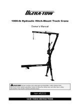
HYDRAULIC HITCH CRANE
OWNER’S MANUAL
WARNING:
Read carefully and understand all ASSEMBLY AND OPERATION
INSTRUCTIONS before operating. Failure to follow the safety rules and other
basic safety precautions may result in serious personal injury.
Item# 38363

Page of 12
2
Thank you very much for choosing an Ultra-Tow product! For future reference, please complete
the owner’s record below:
Model: _______________ Purchase Date: _______________
Save the receipt, warranty and these instructions. It is important that you read the entire manual
to become familiar with this product before you begin using it.
This machine is designed for certain applications only. The distributor cannot be responsible for
issues arising from modification. We strongly recommend this machine not be modified and/or
used for any application other than that for which it was designed. If you have any questions
relative to a particular application, DO NOT use the machine until you have first contacted the
distributor to determine if it can or should be performed on the product.
For technical questions please call 1-800-222-5381.
INTENDED USE
The Ultra-Tow Hydraulic Receiver Hitch Mounted Crane provides three boom capacities: 500, 750
and 1000 pounds. Portable and removable — take it to your job site. No permanent installation is
required, so it frees up truck bed space. Perfect for moving heavy items such as generators, drum
barrels, pressure washers, tool boxes in and out of your truck. Great for hunters. Crane swivels
360 degrees. Easy assembly required.
TECHNICAL SPECIFICATIONS
Item
Description
3 Boom Positions and Weight Capacities:
500, 750 and 1,000 Lbs.
Lift Range:
From 30” off ground to 84” high
For Use With:
2” x 2” Class III and IV Receiver Hitch
Crane Swivel:
360 Degrees
GENERAL SAFETY RULES
WARNING: Read and understand all instructions. Failure to follow all instructions listed
below may result in serious injury.
CAUTION: Do not allow persons to operate or assemble this crane until they have
read this manual and have developed a thorough understanding of how the hitch mounted
crane works.
WARNING: The warnings, cautions, and instructions discussed in this instruction
manual cannot cover all possible conditions or situations that could occur. It must be
understood by the operator that common sense and caution are factors which cannot be built into
this product, but must be supplied by the operator.
SAVE THESE INSTRUCTIONS

Page of 12
3
IMPORTANT SAFETY CONSIDERATIONS
HYDRAULIC HITCH CRANE USE AND CARE
• Do not modify the hitch crane in any way. Unauthorized modification may impair the function
and/or safety and could affect the life of the equipment. There are specific applications for which
the hitch crane was designed.
• Always check of damaged or worn out parts before using the hitch crane. Broken parts will
affect the hitch crane operation. Replace or repair damaged or worn parts immediately.
• Store idle hitch crane. When hitch crane is not in use, store it in a secure place out of the
reach of children. Inspect it for good working condition prior to storage and before re-use.
• Only set up the crane when the pickup truck is off the highway, in a clear location that is
away from oncoming traffic.
• Before lifting cargo into the truck bed, make sure the truck’s engine is OFF with automatic
transmission in PARK. Manual transmission vehicle’s should be in gear. Chock all wheels for
added safety.
• Adhere to all Department of Transportation (D.O.T.) requirements when using this
product.
• Note the position of the vehicle’s exhaust pipes before setting up the crane. Flammable
goods being lifted by the Crane could come in contact with still hot exhaust pipes and catch fire.
• Setting up the crane, and maneuvering heavy cargo on the crane can be strenuous and
dangerous. This should only be done by individuals who are physically able to handle the
demands of these tasks.
• The crane is for lifting purposes only, not for supporting loads. Quickly support the load
with appropriate jack stands or equivalent, if immediate loading or unloading is not possible. Do
not leave a suspended load unattended.
• Remove the Crane from vehicle’s receiver hitch when crane is not in use.
• Always be aware of dynamic loading. An excess load may be created for a brief instant by a
sudden tug or weight gain, which can result in damage to the crane, the cargo, and/or personal
injury.
• Keep in mind that the warnings previously discussed cannot cover all possible events
and circumstances. It is important that the person setting up, loading/unloading and using this
product use common sense at all times.

Page of 12
4
ASSEMBLY
1. Refer to the Parts List and Assembly Diagram at the end of this manual when following the
steps below. Always wear ANSI approved safety goggles when assembling, setting-up
and using this product. Component parts are heavy. Be careful not to pinch fingers when
handling this product. Assistance from a helper will make product set-up much easier.
2. Set all components on the ground (see photo below)
3. Insert shank of T-Shaped Connector (5) into the pickup truck’s receiver hitch -see photo upper
right. The receiver hitch must be 2” x 2” and rated Class III or Class IV.
4. Align the hole openings on receiver hitch and T-Shaped Connector and put the Hitch Pin (32) in
place. Secure Hitch Pin with the Safety Pin (33).

Page of 12
5
5. Next, use Snapper Pins (22) to attach the 2 Legs (6) and 2 Link Bars (7) to the Base Assembly
(4).
Note: The straight tube section of the Base Assembly must be assembled so that it is parallel
with the ground surface, and the same height as the vehicle’s receiver hitch (see photo above).
To accomplish this, first measure the distance of the vehicle’s receiver hitch to the ground.
When assembling Legs (6), adjustments to Leg Extenders (23) and Link Bars (7) are needed to
assure that the straight tube section of the Base Assembly is the same height as the vehicle’s
receiver hitch.
Attach the upper end of each Leg to the Base Assembly (4) using Snapper Pins (22).
The Link Bar (7) connects middle portion of each Leg to the Base Assembly. Note the different
hole attachment positions, as this will affect the height of the straight tube section of the Base
Assembly.
Use Snapper Pins (22) to secure the Link Bars (7) in place. Compare the height of straight tube
section of Base Assembly to height of vehicle’s receiver hitch; they should be the same height.
Additional height adjustments can be made to the Leg Extenders (23) by re-positioning the Bolt
(27) and Lock Nut (28) to different hole positions. Make adjustments as needed, and secure the
Link Bars (7) in place with the Snapper Pins (22).
6. With Leg assembly now complete, slide the end of straight tube section of Base Assembly into
the T-Shaped Connector (5). Lock these components together by tightening two Bolts (31).
7. Test the stability of the bottom half of the Crane. Make sure Foot Plates (24) are flat on the
ground. Make sure that the T-Shaped Connector (5) is solidly connecting the Crane to the
vehicle’s receiver hitch. The straight tube section of the Base Assembly (4) should be parallel to
the ground. Make sure all hardware and clips are tightly secured in place.
8. Setting up the Boom (1)/Post (2)/Long Ram Jack (3) assembly:
Identify the three components per the photo above right, and connect the three together using
the Bolt/Lock Nut combinations noted in the photo.

Page of 12
6
Once the three components are assembled, make sure they are folded together and held in
place with the adhesive strap. With assistance, carefully lift the Boom/Post/Long Ram Jack
assembly into place on top of the Base Assembly (4). This is a gravity fitting with no hardware
connections. - see photo above right. Note the Stop Pin (18) - see photo below. The Boom can
swivel from side to side; Stop Pin is inserted in either Stop 1 (19) or Stop 2 (20) location.
9. Remove the adhesive strap and open up the Boom (1).
Before using the Jack Handle to raise and lower the Boom, identify the location of the hydraulic
release valve (see photo below left). With the use of the Jack Handle, close the release valve
completely (turn clockwise all the way) before attempting to raise the Boom. Now insert Jack
Handle and pump handle to raise Boom.

Page of 12
7
OPERATION
1. With the pickup truck and the Crane properly and safely positioned next to the cargo to be lifted,
the Crane is ready for operation.
2. Know the weight of the cargo to be lifted. The cargo must be properly strapped and have
attachment couplings that will attach to the Crane’s Hook.
3. The lift range of the Crane is between 30” off the ground to 84” high.
4. Attach the Hook with Chain (8) to the correct maximum weight capacity on the Boom (1) - see
photo below. There are 3 maximum weight settings: 500 lbs., 750 lbs., and 1000 lbs. Remove
Lock Nut (10) and Bolt (9) and re-position Hook with Chain, as needed, to make sure that the
weight of cargo being lifted falls below the maximum weight setting chosen. Replace Bolt and
Lock Nut to hold Hook with Chain in place.
5. Swing the Boom (1) so that it is facing the cargo to be lifted. The cargo must be properly
strapped and have a hanging coupler that will be compatible with the Crane’s Hook.
6. Raise the Boom (1) as previously described (close release valve completely and pump Jack
Handle), or lower the Boom as needed.
Note: Slowly turning the release valve counterclockwise will lower the Boom. Be alert, as
the Boom will quickly descend to its lowest position.
7. Attach the cargo to the Boom’s Hook.
8. Use the Jack Handle to close the hydraulic release valve (turn clockwise completely), and then
pump Jack Handle to slowly raise the Boom and the cargo.
9. With the cargo raised, the Post (2) can be pivoted to move the cargo into the truck bed.
10. With the cargo positioned over the truck bed, slowly turn the hydraulic release valve
counterclockwise and the cargo will be lowered to the truck bed.
11. Remove the cargo’s coupler from the Boom Hook and swing back the Boom to its original
position.

Page of 12
8
12. If work is done, disassemble the Crane by first lowering the Boom to its lowest position. Remove
the Jack Handle (15). Next, fold the Boom (1) to its closed position and with assistance lift it off
the Base Assembly. Disconnect the Crane from the pickup truck by removing the T-Shaped
Connector from the vehicle’s receiver hitch. Legs (6) can then be folded up. Use the storage
Straps (38 and 39) to hold the folded components in place while not in use - see photo below.

Page of 12
9
MAINTENANCE
• Maintain your hitch crane. It is recommended that the general condition of any hitch crane be
examined before it is used. Keep your hitch crane in good repair by adopting a program of
conscientious repair and maintenance. Have necessary repairs made by qualified service
personnel.
• Frequently check the condition of the Crane and the pickup truck’s
receiver hitch. Make sure all components are in good condition. If
the Crane or receiver hitch becomes damaged through an
accident, or if any other type of damage is noted, they should be
replaced. Check to make sure that all hardware is tightly secured
in place.
• If you notice that the efficiency of the Long Ram Jack is
decreasing, it may be due to air being trapped within the hydraulic
system. In this situation, the hydraulic system needs to be
bled of this excess air.
A. Use the Jack Handle to open the air release valve; turn Jack
Handle about 1-1/2 turns counterclockwise.
B. Remove the pliable oil fill plug on the side of the Jack - see
photo below. Carefully turn it and pull it out.
C. Pump the Jack Handle rapidly for several cycles to remove
excess air from the system.
D. Turn air release valve clockwise to close the system.
E. Carefully replace the oil fill plug.
• Keep the Crane clean and periodically lubricate moving parts
• Replacing hydraulic oil: It is important that hydraulic oil be replaced at least once per year (or
more, if Crane is frequently used). Only use good quality hydraulic oil and never mix different
brands of oil together.
• To change hydraulic oil:
A. Remove the Jack from the Crane. Lower the Jack’s ram completely.
B. Locate the oil fill plug on the side of the Jack and remove it.
C. Drain the old oil from the hydraulic system.
D. Fill the hydraulic system with new high quality hydraulic oil; fill to the lower edge of the fill
hole.
E. Bleed air from the hydraulic system (see previous instructions).
F. Top off the hydraulic system with more oil and replace the oil fill plug.

Page of 12
10
DIAGRAM & PARTS LIST

Page of 12
11
For replacement parts and technical questions, please call 1-800-222-5381.

Page of 12
12
WARRANTY
1 Year Warranty
Distributed by
Northern Tool + Equipment Co., Inc.
Burnsville, Minnesota 55306
NorthernTool.com
Made in China
/