Page is loading ...

1 OF 42
Title
HUBBUS HANDHELD
PROGRAMMER AND TESTER
TYPE HHP1-H
USER MANUAL
Document Number
125-198-12
Issue
02

HubBus Handheld Programmer and Tester 2 OF 42 125-198-12
HHP1-H USER MANUAL Issue: 02
Revision Control
02 Issue for registration 2020.12.11 NI SC PC
01A/B(02) Programming procedure +
instructions 2020.11.18 NI SC PC
01 Release 2020.10.28 NI SC PC
Issue Details Date Written Designed Approved
Austdac Pty Ltd
Unit 1 / 42 Carrington Road
Castle Hill NSW 2154
Australia
PO Box 6486
Baulkham Hills Business Centre
NSW 2153
Australia
Phone: + 61 2 8851 5000
Fax: + 61 2 8851 5001
Website: www.austdac.com.au
Copyright 2020
This document remains the property of Austdac Pty. Ltd. It is subject to its recall and must not be reproduced
in part or whole or its contents divulged to third parties without prior written approval from Austdac Pty Ltd.

HubBus Handheld Programmer and Tester 3 OF 42 125-198-12
HHP1-H USER MANUAL Issue: 02
TABLE OF CONTENTS
Revision Control ................................................................................................................................ 2
TABLE OF CONTENTS .................................................................................................................... 3
FIGURES .......................................................................................................................................... 4
TABLES ............................................................................................................................................ 5
1 INTRODUCTION ........................................................................................................................... 6
2 WARNINGS AND PRECAUTIONS ................................................................................................ 7
2.1 Warnings ................................................................................................................................. 7
2.2 Symbols .................................................................................................................................. 7
2.3 Precautions ............................................................................................................................. 8
2.3.1 USER ACCESS ............................................................................................................... 8
2.3.2 STORAGE, INSTALLATION, USE AND MAINTAINANCE REQUIREMENTS ................ 8
2.3.2.1Storage ................................................................................................................... 8
2.3.2.2Installation and conditions of use ........................................................................... 8
3 Handheld Overview ........................................................................................................................ 9
3.1 Case ........................................................................................................................................ 9
3.2 Front Panel ........................................................................................................................... 10
3.3 Ports ...................................................................................................................................... 10
3.3.1 HubBus Port ................................................................................................................... 10
3.3.2 Configuration Port .......................................................................................................... 11
3.3.3 HubBus Cable ................................................................................................................ 11
3.3.4 Configuration Cable ....................................................................................................... 12
3.4 Batteries ................................................................................................................................ 12
3.5 Micro SD Card ...................................................................................................................... 13
3.6 Keypad .................................................................................................................................. 14
3.6.1 Default/Navigation Mode ................................................................................................ 15
3.6.2 Alpha/Numeric Mode ...................................................................................................... 16
3.6.3 Function Mode ............................................................................................................... 16
3.7 Bluetooth ............................................................................................................................... 16
4 Operation ..................................................................................................................................... 17
4.1 Main Menu ............................................................................................................................ 17
4.1.1 Mode Selection .............................................................................................................. 17
4.1.2 Battery Status ................................................................................................................. 17
4.2 HubBus Mode ....................................................................................................................... 17
4.2.1 I/O MAP
.......................................................................................................................... 17
4.2.2 HUBBUS TESTER ......................................................................................................... 18
4.2.2.1Latched ................................................................................................................. 19
4.2.2.2Momentary Hold ................................................................................................... 20
4.2.3 ANALOG ........................................................................................................................ 21
4.2.4 CONTROL CHANNELS ................................................................................................. 21
4.2.5 INTERRUPT COUNT ..................................................................................................... 22
4.3 Modbus Mode ....................................................................................................................... 22
4.3.1 INFORMATION FIELD ................................................................................................... 22
4.3.2 DIAGNOSTIC FIELD ...................................................................................................... 22
4.3.3 CONFIGURATION ......................................................................................................... 23
4.3.3.1Configuration Process .......................................................................................... 23
4.3.3.2Numeric Value Entry ............................................................................................. 25
4.3.3.3Set Value Entry ..................................................................................................... 25
4.3.3.4Logic Entry ............................................................................................................ 26
4.3.4 LOGGING ...................................................................................................................... 28
4.3.4.1EVENT TABLE ..................................................................................................... 29
4.3.5 Upload/Download Menu ................................................................................................. 29
4.3.5.1UPLOAD CONFIG ................................................................................................ 29
4.3.5.2DOWNLOAD CONFIG ......................................................................................... 31

HubBus Handheld Programmer and Tester 4 OF 42 125-198-12
HHP1-H USER MANUAL Issue: 02
4.3.5.3SW UPDATE ........................................................................................................ 32
4.3.6 MODBUS SETTING ....................................................................................................... 33
4.4 Tethered Mode ...................................................................................................................... 34
4.5 Handheld Mode ..................................................................................................................... 34
4.5.1 LCD BACKLIGHT ........................................................................................................... 34
4.5.2 SET DATE/TIME ............................................................................................................ 35
4.5.3 ABOUT ........................................................................................................................... 35
4.5.4 SYSTEM UPDATE ......................................................................................................... 36
Annex A.Specifications .......................................................................................................... 39
Annex B.Cables ..................................................................................................................... 40
B.1HubBus Network Interface ...................................................................................... 40
B.2HubBus Module Configuration ................................................................................ 40
Annex C.AUSTDAC HHP INTERFACE APPLICATION ......................................................... 41
FIGURES
Figure 1: HubBus Handheld Programmer and Tester: Type HHP1-H .............................................. 6
Figure 2: Rubber case ...................................................................................................................... 9
Figure 3: Kickstand ........................................................................................................................... 9
Figure 4: HHP1-H front panel view ................................................................................................. 10
Figure 5: Ports ................................................................................................................................ 10
Figure 6: HubBus network interface cable ...................................................................................... 11
Figure 7: HHP1-H HubBus port ...................................................................................................... 11
Figure 8: HubBus Configuration cable ............................................................................................ 12
Figure 9: HHP1-H configuration port ............................................................................................... 12
Figure 10: HHP1-H Battery Compartment ...................................................................................... 13
Figure 11: Battery Orientation ......................................................................................................... 13
Figure 12: Micro SD card slot ......................................................................................................... 14
Figure 13: HHP1-H Keypad Layout ................................................................................................ 14
Figure 14: Screen - HubBus Map - Emergency Interrupt ................................................................ 18
Figure 15: Screen - HubBus Map - No Network ............................................................................. 18
Figure 16: Screen - HubBus Tester – Latch Output ........................................................................ 19
Figure 17: HubBus Tester - Momentary Transmit On ..................................................................... 20
Figure 18: HubBus Tester - Momentary Transmit Off ..................................................................... 20
Figure 19: HubBus Tester - Exit Action ........................................................................................... 20
Figure 20: HubBus - Analogue Decode .......................................................................................... 21
Figure 21: HubBus - Control Channels ........................................................................................... 21
Figure 22: HubBus - Interrupt Counts ............................................................................................. 22
Figure 23: Modbus Mode - Information Mode ................................................................................. 22
Figure 24: Modbus Mode - Diagnostic Mode .................................................................................. 22
Figure 25: Modbus Mode - Configuration Screen ........................................................................... 23
Figure 26: Configuration process - select parameter ...................................................................... 23
Figure 27: Configuration process - modify parameter ..................................................................... 24
Figure 28: Configuration process - Save or Revert ......................................................................... 24
Figure 29: Configuration Process - Parameter Saved .................................................................... 25
Figure 30: Configuration Process - Parameter Reverted ................................................................ 25
Figure 31: Modbus Mode - Configuration Numeric Entry ................................................................ 25
Figure 32: Modbus Mode - Configuration Fixed Values .................................................................. 26
Figure 33: Logic Configuration – Enter ........................................................................................... 26
Figure 34: Logic Configuration - Select Range ............................................................................... 26
Figure 35: Logic Configuration – Enter Edit Mode .......................................................................... 27
Figure 36: Logic Configuration – Select Address ............................................................................ 27
Figure 37: Logic Configuration - Change Value .............................................................................. 27
Figure 38: Logic Configuration - Save or Revert ............................................................................. 28
Figure 39: Logic Configuration - Saved Change ............................................................................. 28

HubBus Handheld Programmer and Tester 5 OF 42 125-198-12
HHP1-H USER MANUAL Issue: 02
Figure 40: Modbus Mode – Log statistics ....................................................................................... 28
Figure 41: Modbus Mode - Log Entry ............................................................................................. 29
Figure 42: Modbus Mode - Log Unavailable ................................................................................... 29
Figure 43: Modbus Mode - Upload Configuration Select ................................................................ 30
Figure 44: Modbus Mode - Upload Configuration – Upload in progress ......................................... 30
Figure 45: Modbus Mode - Upload Configuration – Upload Complete ........................................... 30
Figure 46: Modbus Mode - Download Configuration - Saving ........................................................ 31
Figure 47: Modbus Mode - Download Configuration – Save Filename .......................................... 32
Figure 48: Modbus Mode – Firmware Download – File Select ....................................................... 33
Figure 49: Modbus Mode – Firmware Download – Successful ....................................................... 33
Figure 50: Modbus Mode – Firmware Download – Failed .............................................................. 33
Figure 51: Modbus Mode – Modbus settings .................................................................................. 34
Figure 52: Bluetooth Mode Screen ................................................................................................. 34
Figure 53: Handheld Settings - LCD Backlight ............................................................................... 35
Figure 54: Handheld Settings - Time and Date ............................................................................... 35
Figure 55: Handheld Settings - Handheld Info/About Screen ......................................................... 36
Figure 56: Handheld Settings - Firmware Update Confirmation ..................................................... 36
Figure 57: Handheld Settings - Firmware Update Battery Warning ................................................ 37
Figure 58: Handheld Settings - Firmware Update Invalid File ........................................................ 37
Figure 59: Handheld Settings - Firmware Update No Valid File Found .......................................... 37
Figure 60: Handheld Settings - Firmware Update In Progress ....................................................... 37
Figure 61: HubBus Network Interface Cable Drawing .................................................................... 40
Figure 62: HubBus Module Interface Cable Drawing ...................................................................... 40
Figure 63: AUSTDAC HHP INTERFACE application startup screen .............................................. 41
Figure 64: List of files on the connected HHP1 device ................................................................... 41
Figure 65: List of files on the connected HHP1 device ................................................................... 42
TABLES
Table 1: Warning Symbols ................................................................................................................ 7
Table 2: HubBus Port Pinout .......................................................................................................... 10
Table 3: Configuration Port Pinout .................................................................................................. 11
Table 4: Keypad Functions ............................................................................................................. 15
Table 5: HubBus Map Symbols ...................................................................................................... 18
Table 6: Logic function states ......................................................................................................... 26
Table 7: Specifications .................................................................................................................... 39

HubBus Handheld Programmer and Tester 6 OF 42 125-198-12
HHP1-H USER MANUAL Issue: 02
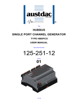
1 INTRODUCTION
The HubBus Handheld Programmer and Tester Type HHP1-H is a portable device which is
used for:
Real-time monitoring of the HubBus network
Configuration of HubBus network components
View module information and diagnostic data
Firmware upgrades of HubBus system modules
Configuration storage and data retrieval.
The handheld has a large and bright backlit LCD screen which is easy to read, providing
information at a glance. Menu-specific content makes for easy and intuitive navigation.
Additionally, it has large buttons with positive tactile response for ease of use even with
gloves on.
In the HubBus network diagnostics mode, the user may monitor in real time the status of all
2000 HubBus digital I/O channels, value of analogue transmissions, simulate network
devices, status of emergency and auxiliary interrupts and the current network configuration
status.
There is micro SD-card support which provides additional memory capacity. Micro SD
cards can be used to deliver firmware upgrades, configuration may be stored and retrieved
from the HubBus modules.
Standard off the shelf AA sized alkaline batteries provide power not only for the handheld
but also for HubBus modules which are unpowered.
A built-in Bluetooth transceiver is available for transferring data to and from a PC.
Figure 1: HubBus Handheld Programmer and Tester: Type HHP1-H

HubBus Handheld Programmer and Tester 7 OF 42 125-198-12
HHP1-H USER MANUAL Issue: 02
2 WARNINGS AND PRECAUTIONS
2.1 WARNINGS
WARNING: The HubBus Signal -ve line must not be tied to any common, 0V, ground or
Earth points.
BATTERY Do not mix old and new batteries.
WARNING: Do not mix alkaline, standard or rechargeable batteries.
Remove batteries when product is stored for a long period of time or when
batteries are exhausted.
Dispose of exhausted batteries properly.
Non-rechargeable batteries are not to be recharged.
Rechargeable batteries are to be removed from the device before being
charged.
Only the recommended batteries or equivalent are to be used, volts and size.
Keep all batteries away from children.
Batteries are to be inserted with correct polarity.
WARNING: This product may contain chemicals known to the State of California to cause
cancer and birth defects or other reproductive harm.
2.2 SYMBOLS
Markings that may be used across the HubBus range of products to indicate precautions
that must be taken to maintain safe operation of the system.
Direct Current (DC) Supply
Earth (ground) Terminal
Caution, possibility of electric shock
Caution (refer to user manual)
Table 1: Warning Symbols

HubBus Handheld Programmer and Tester 8 OF 42 125-198-12
HHP1-H USER MANUAL Issue: 02
2.3 PRECAUTIONS
Only qualified personnel shall install and service the HHP1-H.
2.3.1 USER ACCESS
There are no user serviceable parts within the HHP1-H. The user should not open or
disassemble the HHP1-H.
The HHP1-H must only be repaired by an Austdac authorized repairer.
2.3.2 STORAGE, INSTALLATION, USE AND MAINTAINANCE REQUIREMENTS
The HHP1-H should only be installed, operated and maintained by qualified
personnel in accordance with the condition of safe use as outlined in this manual.
If cleaning is required, use a moist wipe. Do not use chemical cleaners as it may
react with materials.
Ensure that all instructions and warnings are observed.
2.3.2.1 Storage
The specified storage temperature must be maintained during storage.
2.3.2.2 Installation and conditions of use
Prior to installation the HHP1-H should be inspected for the following;
Any external damage to the enclosure.

HubBus Handheld Programmer and Tester 9 OF 42 125-198-12
HHP1-H USER MANUAL Issue: 02
3 Handheld Overview
3.1 CASE
The HHP1-H comes with a protective rubber case. The HHP1-H may be removed from
the rubber case for battery replacement and access to the micro-SD card slot.
Figure 2: Rubber case
The protective rubber case has a built-in kickstand for easy of viewing the display. To
use, simply pull the base of the kickstand out with your finger.
Figure 3: Kickstand

HubBus Handheld Programmer and Tester 10 OF 42 125-198-12
HHP1-H USER MANUAL Issue: 02
3.2 FRONT PANEL
The front panel of the HHP1-H consists of an LCD display and 16 multi-functional buttons.
Figure 4: HHP1-H front panel view
3.3 PORTS
The top of the HHP1-H enclosure has two ports. These ports are accessible through the
protective rubber case.
Figure 5: Ports
3.3.1 HubBus Port
Pin Function
1 HubBus Si
g
nal +
2 HubBus Si
g
nal +
Table 2: HubBus Port Pinout
Configuration
Port
HubBus
Port

HubBus Handheld Programmer and Tester 11 OF 42 125-198-12
HHP1-H USER MANUAL Issue: 02
3.3.2 Configuration Port
Pin Function
1 3V3 Console Port Power
2 9V Transmitter Power
3 0V
4 TTL Tx
5 3V3 Console Port Power
6 RS485 B-
7 RS485 A+
8 TTL Rx
Table 3: Configuration Port Pinout
3.3.3 HubBus Cable
The HubBus network monitoring cable supplied with the HHP1-H has a boot-laced
end to allow the user to fit their desired type of plug to interface to the HubBus
network.
Figure 6: HubBus network interface cable
The HubBus network interface cable plugs into the 2-pin Molex mini-fit connector at
the top of the HHP1-H as shown.
Figure 7: HHP1-H HubBus port
2-Pin
HHP1-H
HubBus Port
Boot-laced
lead

HubBus Handheld Programmer and Tester 12 OF 42 125-198-12
HHP1-H USER MANUAL Issue: 02
3.3.4 Configuration Cable
The HubBus module configuration cable supplied with the HHP1-H has three
connectors on the cable. The 8-pin Molex mini-fit connector is plugged into the
HHP1-H. The 4-pin connector is for connection to the HubBus module display and
interface board’s configuration port and the 10-pin Molex mini-fit connector is for
direct connection to HBTX2D transmitters and pull-key stations.
Figure 8: HubBus Configuration cable
The HubBus configuration cable plugs into the 8-pin Molex mini-fit connector at the
top of the HHP1-H as shown.
Figure 9: HHP1-H configuration port
3.4 BATTERIES
The HHP1-H uses 4 standard AA sized batteries. The battery compartment is on the
underside of the enclosure. Remove the HHP1-H from the protective rubber case and
slide off the battery compartment cover to access the battery compartment.
4-Pin
Configuration
Connector
10-Pin
HBTX2D
Connector
8-Pin HHP1-H
Configuration
port

HubBus Handheld Programmer and Tester 13 OF 42 125-198-12
HHP1-H USER MANUAL Issue: 02
Figure 10: HHP1-H Battery Compartment
Ensure batteries are orientated correctly. Battery polarity is embossed in the base of the
battery compartment for each cell.
Figure 11: Battery Orientation
3.5 MICRO SD CARD
Your HHP1-H is supplied with a micro SD card from Austdac. The capacity and make of
card may differ over time. Use of cards not supplied by Austdac may fail to work correctly
with the HHP1-H. The maximum storage capacity the HHP1-H can support is 8GB and
the micro SD card should be rated as a class 10. Please contact Austdac if you require a
new micro SD card.
The micro SD card slot is on the bottom end of the enclosure. To access the micro SD
card, remove the HHP1-H from the protective rubber case and gently press the edge of
the micro SD card and it will pop out. Be careful that the card does not fly out. Micro SD
cards are fragile and may be easily damaged.

HubBus Handheld Programmer and Tester 14 OF 42 125-198-12
HHP1-H USER MANUAL Issue: 02
Re-insert the micro SD card by pushing the card in until it clicks into position. Orientation
is critical for correct insertion, with the keypad facing upwards, the micro SD card should
be placed in with contacts facing upwards.
Figure 12: Micro SD card slot
3.6 KEYPAD
Keypad lay out and functions are given below. Functionality may change depending on
the mode the handheld is in.
Figure 13: HHP1-H Keypad Layout

HubBus Handheld Programmer and Tester 15 OF 42 125-198-12
HHP1-H USER MANUAL Issue: 02
Key Default/
Navigation Numeric
Power ON/OFF
(Hold for 3 seconds)
Delete/Backspace
- +/- 1 Home
- ABC 2 Repeat
- DEF 3
Page
Up
- GHI 4 Help
- JKL 5 View
- MNO 6
Page
Down
(LEFT) PQRS 7 -
(UP) TUV 8 -
(RIGHT) WXYZ 9 -
MENU #/! 0 -
(DOWN) SPACE . -
Enter
Table 4: Keypad Functions
NOTE: Greyed out keys currently have no functionality assigned. May be used in future
firmware revisions.
3.6.1 Default/Navigation Mode
The keypad on HHP1-H by default (during power ON and when in the main menu)
has the “FUNC” and “ALPHA” modes turned OFF.
The valid keys are “ENTER”, “MENU”, “UP”, “DOWN” and “POWER”.
Pressing the ENTER key moves into the sub-menus or into the edit mode.
Pressing the MENU key moves back to the previous menu or exit the edit mode and
enter the navigate mode. It also toggles between the “Main menu” and the HHP1-H
logo screen.
The UP-ARROW / DOWN-ARROW key press moves the menu selection arrow
accordingly during navigation mode. When the HHP1-H is in selection mode, it
allows the user to select a value/string from the predefined list.

HubBus Handheld Programmer and Tester 16 OF 42 125-198-12
HHP1-H USER MANUAL Issue: 02
Pressing the POWER key for approximately 3 seconds will either turn the HHP1-H
ON or OFF.
3.6.2 Alpha/Numeric Mode
On the HHP1-H the ALPHA/NUMERIC mode is functional when it’s in the edit mode.
This can’t be selected simultaneously with the function mode.
The ALPHA key press will toggle between ALPHA and NUMERIC mode. The
current mode of the device will be displayed on the top right-hand corner of the
screen with the notations;
A – Alpha mode
N – Numeric mode
When the device is in the numeric mode, the user can enter the values from ‘0’ to ‘9’
as required.
When the device is in the alpha mode, the user can enter characters from ‘A’ to ‘Z’
as required. The alpha keys are multi-press keys i.e. user must press two or three
times to use the second or third characters respectively on the same key. For
example, if the user wants to enter character ‘C’, the user needs to press the key
labelled ‘2’ three times with a maximum delay of 3 seconds between each key
press.
3.6.3 Function Mode
On the HHP1-H the function mode is for future functionality and it doesn’t have any
behaviour currently.
3.7 BLUETOOTH
The Bluetooth version used on the hand-held programmer is Bluetooth 2.1. The Bluetooth
profile used is Serial Port Profile (SSP) and the data transfer rate is 300 Kbps.
The hand-held programmer uses the Bluetooth for transferring the “Config” (configuration)
and “Hex” files to and from the Windows PC using the AUSTDAC HHP INTERFACE
application. Also, the user can “Delete” and “Rename” files on the HHP1-H using the
HHP INTERFACE application.
Every HHP1-H has a unique Bluetooth identification name with the common string
“AustdacHHP1-” followed by the unique ID of the Bluetooth interface.
For example:
“AustdacHHP1-B8A4”.
The user can find the particular HHP1-H device name on the “file transfer” screen. Refer
to FILE TRANSFER section for more details.

HubBus Handheld Programmer and Tester 17 OF 42 125-198-12
HHP1-H USER MANUAL Issue: 02
4 Operation
4.1 MAIN MENU
The main menu screen allows for the section of the desired operating mode.
Additionally, from the main menu, the handheld will automatically enter the HubBus mode
if it detects an active HubBus network connected or alternatively, if it receives valid
responses on the Modbus interface it will jump to the Modbus menu.
4.1.1 Mode Selection
HUBBUS For HubBus network tester and diagnostic functionality.
MODBUS For module configuration and diagnostics.
TETHERED Bluetooth connectivity mode.
HANDHELD Handheld based settings.
4.1.2 Battery Status
The HHP1-H displays its battery level on the top right-hand corner when it is in the
“Main menu”. The icon indicates the four stages of battery level as below,
100%
75%
50%
25%
The HHP1-H device is operable until it reaches 25%. When the battery level goes
below 25%, on basis of safety the HHP1-H prompts the user to replace with the new
batteries and the user is not allowed to perform any operation with the device until
new batteries are inserted.
4.2 HUBBUS MODE
4.2.1 I/O MAP
The HubBus I/O map shows all the 2048 HubBus channel at a glance. The HubBus
I/O map is in the form of a matrix with every page displaying 100 number of
channel’s status. User can press “Up Arrow” / “Down Arrow” to move across the
2048 HubBus channels in groups of 100 channels per page.
The top right corner of the I/O map screen shows the base channel number and
below are the consecutive 100 number of channels that are currently displayed.
The 100 channels per page are displayed as 10 channels per line.

HubBus Handheld Programmer and Tester 18 OF 42 125-198-12
HHP1-H USER MANUAL Issue: 02
Below are the symbols used to show the status of channels:
S
y
mbol Status
- Off-line
X Fault
OFF / Lo
g
ic 0
ON / Lo
g
ic 1
Table 5: HubBus Map Symbols
Whenever an emergency interrupt is being transmitted by any device on the HubBus
network, the character ‘E’ will be displayed on the top left corner of the I/O map
screen like below.
Figure 14: Screen - HubBus Map - Emergency Interrupt
When the HHP1-H is not actually connected to a HubBus network, entering to I/O
map will display “NO HUBBUS” message to the user until it is connected back to the
HubBus network.
Figure 15: Screen - HubBus Map - No Network
4.2.2 HUBBUS TESTER
The HHP1-H has the ability to simulate devices on the HubBus network by
transmitting HubBus channels individually.
There are two modes of transmitting the digital signal on the HubBus network. They
are:
Latch
Momentary Hold
By default, the arrow will be pointing to the first field “Tx Latch”.
To enable the “Latch” mode, the Tx Latch should be “YES” and to enable the “Hold”
mode, the Tx Latch should be “NO”.

HubBus Handheld Programmer and Tester 19 OF 42 125-198-12
HHP1-H USER MANUAL Issue: 02
4.2.2.1 Latched
With the TX-Latch enabled, there will be two input fields.
Channel
Offset
In the channel field, the user can use the numeric keypad to input the desired
channel number. Once the channel field is entered, the user should press the
“ENTER” key to confirm it and the HHP1-H will be displaying the corresponding
channel’s status in multiples of 10 at the bottom of the screen.
The user can then input the offset of the required channel to be controlled using the
numeric keypad in the offset field.
Note that the keypad is automatically set to alpha mode.
For example, if the user wants to control the 9
th
channel. The steps will be as
follows,
User can input value between 0-9 in the channel field.
The HHP1-H will be displaying the status of the channels 0-9 in the
bottom of the screen.
User should input value 9 in the offset field.
Now the transmit state will be latched in the HubBus network.
Figure 16: Screen - HubBus Tester – Latch Output
Each time when the corresponding value is inputted in the offset field, the transmit
state changes in the below order,
OFF
ON
FAULT
NONE (no transmit)
In this mode it is possible to "latch" the status on one or more channels. This means
that the HHP1-H will continue transmitting the channel(s) set status even though the
corresponding transmission button is released. To cancel the transmission on a
channel, press the corresponding transmission button again until the NONE status is
reached. The latched transmission will continue even if the mode is changed.

HubBus Handheld Programmer and Tester 20 OF 42 125-198-12
HHP1-H USER MANUAL Issue: 02
4.2.2.2 Momentary Hold
With the TX-Latch enabled, there will be three input fields.
Channel
Offset
Tx Value
The channel and offset field are the same as in Latch mode.
The status which needs to be transmitted on the channel should be set on the “Tx
Value” field using the “Up Arrow” / “Down Arrow”. The user should then input the
offset of the required channel using the numeric keypad in the offset field.
Then the user can press the numbers 0-9 to activate the corresponding channel in
the “Offset” field.
Note that the keypad is automatically set to numeric mode.
The HHP1-H will stop transmitting the channel once the user releases the key press.
Figure 17: HubBus Tester - Momentary Transmit On
Figure 18: HubBus Tester - Momentary Transmit Off
While exiting the HubBus tester mode, the HHP1-H prompts to the user for clearing
the transmitting HubBus buffer. User can press “ENTER” to clear the buffer and exit
tester mode or can press “Menu” to exit the tester mode leaving the transmitting
buffer un-touched.
Figure 19: HubBus Tester - Exit Action
/