Page is loading ...

Instruction Manual
Active Surge Eliminator
104050 – X – X

Instruction Manual
Page
2
of
24
Issue: 12.6
Providing all conditions of safe use stated within the product manuals have been complied with and that
the final equipment into which this product is installed has been re-assessed as required, in accordance with
essential health and safety requirements of the above standards, directives and statutory instruments and
also installed in accordance with any applicable local codes of practice.
Surge chamber/eliminator -104050, 104052, 104053,
108120,
Solvent and Water based Materials
Zone 1 & 2
II 2 G X IIB T4
Suitable for use in hazardous area:
Protection Level:
This Product is designed for use with:
Product Description
Manufacturer: Binks,
Ringwood Road,
Bournemouth, BH11 9LH. UK
Pressure Equipment Regulations 1999 (SI 1999/2001)
by complying with the following statutory documents and harmonized standards:
EN ISO 12100: Safety of Machinery - General Principles for Design
EN ISO 4413: Hydraulic Fluid Power - General Rules and safety requirements
1/11/12
EN 12621: Machinery for the supply and circulation of coating materials under pressure - Safety
requirements
EN 13463-1: Non electrical equipment for use in potentially explosive atmospheres - Basic methods and
requirements
EN 13463-5: Non electrical equipment for use in potentially explosive atmospheres - Protection by
constructional safety
D Smith (General Manager)
ATEX Directive 94/9/EC
EU Declaration of Conformity
We: Binks declare that the above product conforms with the Provisions of:
Machinery Directive 2006/42/EC
EN1127-1: Explosive atmospheres - Explosion prevention - Basic concepts
EN ISO 4414: Pneumatic Fluid Power - General Rules and safety requirements

Instruction Manual
Page
3
of
24
Issue: 12.6
Index
Section
1.1 General Description
1.2 Operating Principle
1.3 Specification
1.4 Fitting Selection
2.1 Installation – General
2.2 Installation – Mounting
2.3 Installation – Setting to work
3.1 Assembly Procedure
3.2 Assembly Drawing
3.3 Parts Lists
4.1 Important Information
4.2 Maintenance
4.3 Fault Finding
4.4 Spare Parts Lists
5.1 Accessories

Instruction Manual
Page
4
of
24
Issue: 12.6
General Description – Section 1.1
Introduction
A complete range of Binks surge elimination chambers is available to suit both
technical and commercial requirements.
The surge elimination chamber is designed to counteract fluctuations in fluid
pressure normally seen during a reciprocating pump stroke change over.
The fluid chamber is suitable for use with waterborne and conventional paint types.
Both conventional and ‘Active’ units are available with flow through flushable or
single port connections.
Surge elimination chambers should be located on the fluid outlet of the circulating
pump for optimum operational performance.
Models are available with a range of standard or customer specified connections,
see selection chart (section 1.4) for variants. The required connections are factory
fitted and not intended for removal in the field.
Active Surge Eliminators
Features
Self compensating design eliminating manual charging with
compressed air
Active control reacts to changes in fluid system pressure
Flushable fluid chamber
Fluid connection options available
Direct mounting to the paint pump
Increased air volume for improved fluid damping (+ / - 1%)

Instruction Manual
Page
5
of
24
Issue: 12.6
Operating Principle – Section 1.2
Active Surge Eliminators
The surge eliminators consist of a lower fluid and upper air chamber separated by a
flexible diaphragm. The air chamber is continually supplied with compressed air at a
pressure in excess of the maximum desired fluid pressure, Compressed air is used
for initial charging and as required to compensate for a change to a higher paint
pressure dynamically set on the Paint Pump.
Any air leaks, whilst not desirable are also compensated for.
Fluid is pumped into and around the circulation system filling the lower chamber of
the surge eliminator.
At the point of pump stroke change over, the fluid pressure drops causing the
diaphragm to deflect and apply pressure to the fluid in the lower chamber,
compensating for the momentary reduction in fluid pressure and flow.
The larger air volume available with active surge eliminators greatly improves the
performance as fluid surge at pump stroke change over is virtually eliminated.
The use of the additional air reservoir capacity is only made possible by the
automatic compensation feature to the compressed air pressure.
The follower shaft is permanently connected with the diaphragm and operates a
spool controlling the charging and exhausting of compressed air in the upper
chamber.
When the diaphragm lifts due to an increase in fluid pressure the spool allows
compressed air into the upper chamber until the higher fluid pressure is balanced
with air pressure. (See diagram 1)
When the diaphragm falls due to a decrease in fluid pressure the spool allows
compressed air to exhaust from the upper chamber to maintain a balance with the
new fluid pressure. (See diagram 2)
In normal operation the diaphragm is maintained in its optimum working position
within a ‘dead band’ stroke of 15 mm (See diagram 3) This maintains the maximum
effectiveness of the diaphragm to automatically compensate for the changes in fluid
pressure at pump stroke change over.

Instruction Manual
Page
6
of
24
Issue: 12.6
Operating Principle – Section 1.2
Diagram 1

Instruction Manual
Page
7
of
24
Issue: 12.6
Operating Principle – Section 1.2

Instruction Manual
Page
8
of
24
Issue: 12.6
Operating Principle – Section 1.2
Diagram 3

Instruction Manual
Page
9
of
24
Issue: 12.6
Specification – Section 1.3
Air Connectio
ns
Air Quality required
ISO 8573.1. to 1
.5.2
Dirt
0.3
Microns
Water
+7ºC at 7bar
Oil 0.1 mg/m³
Air Intensifier
-
108121
Input pressure
5 Bar Maximum
¼ BSP
Output pressure
4 x Input pressure
Direct Mounting (or ¼BSP)
Output volume
60
Litres/Min
Air Reservoir
-
108120
Rated pressure
16 Bar Maximum
Inlet connection
½ BSP
Pressure relief / exhaust valve
16 Bar set pressure
Active Chamber
Input pressure
16 Bar Maximum
1/8 BSP
Exhaust connection
1/4 BSP
Reserv
oir connection
½ BSP
Fluid Connections
-
Examples
Fluid Chamb
er
300 Series
Stainless Steel
Input pressure
16 Bar Maximum
*
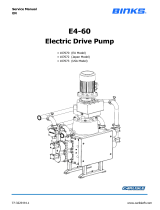
Model 104050
-
B
-
B
(was 106934)
Inlet
–
2’’ Sanitary
Outlet
–
2’’ Sanitary
Model 104050
-
A
-
A
(was 106943)
Inlet
–
2’’ NB Flange
Outlet
–
2’’ NB Flange
Model 104050
-
L
-
L
(was 107017)
Inlet
–
1’’ Sanitary
Outlet
–
1’’ Sanitary
Model 104
0
50
-
C
-
C
(was 107046)
Inlet
–
1 1/2’’ Sanitary
Outlet
–
1 1/2’’ Sanitary
* Higher Working pressures up to 25 Bar are possible if required when combined with an air
reservoir
which is rated at this pressure.

Instruction Manual
Page
10
of
24
Issue: 12.6
Model Selection – Section 1.4
INLET / OUTLET FITTING SELECTION TABLE
SUFFIX
PART No DESCRIPTION REMARKS
A 192553 FITTING - M45 x SLIP FLANGE ASSEMBLY DN 50 BS4504 PN16
B
192554
FITTING - M45 x 2" SANITARY STANDARD
C
192555
FITTING - M45 x 1 1/2" SANITARY STANDARD
D 192556 FITTING - M45 x 1 1/2" NPT (FEMALE)
E 192557 FITTING - M45 x 1 1/2" BSPT (FEMALE)
F 192558 FITTING - M45 x 42 MM COMPRESSION COUPLING DIN 2353
G 192559 FITTING - M45 x 1 1/4" BSP (H)
H 192560 FITTING - M45 x 1 1/2" BSP (H)
I 192561 FITTING - M45 x ECOFITTING DN32 (35 O/D)
J 192562 FITTING - M45 x ECOFITTING DN40 (40 O/D)
K 192563 FITTING - M45 x ECOFITTING DN50 (50 O/D)
L
192564
FITTING - M45 x 1" SANITARY STANDARD
X NO FITTINGS SUPPLIED INTERNAL USE
A
-
B
-
C
etc

Instruction Manual
Page
11
of
24
Issue: 12.6
Installation - General – Section 2.1
To achieve the best performance from the surge elimination unit the ideal location is
direct mounting on the paint pump outlet connection
A suitable bracket should be used to support the surge eliminator in the event that
the paint pump or connecting pipework is removed for maintenance operations.
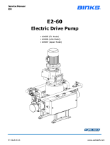
Installation - Mounting – Section 2.2
Model shown 104050 - B - B
(I
nlet and Outlet
-
2” Sanitary Fittings

Instruction Manual
Page
12
of
24
Issue: 12.6
Installation – Setting to Work – Section 2.3
General
The surge eliminator is pressure tested with demineralised water; the fluid chamber
should be flushed with suitable material prior to use.
If any circulating system pressure testing is carried out with the surge eliminator in
position then the fluid pressure should not exceed 24 Bar, the air pressure to the
upper chamber must be disconnected.
Circulating system flushing can be carried out with the surge eliminator in position;
however, the air pressure to the upper chamber should be disconnected, as normal
practice is to flush the pipework with a low system back pressure.
Following pressure testing and flushing procedures, the fluid diaphragm may need
replacing prior to use in production if the flushed system held contaminates that
could impregnate and damage the diaphragm.
Ensure that the unit is correctly grounded to earth to prevent any ‘static’ build up.
Air Connections
Connect the air reservoir hose supplied with the Air Reservoir Kit (108120) to the
top dish ½ BSP port. The air reservoir should be mounted on a suitable bracket in
close proximity to the surge eliminator so that the connecting hose is not stressed.
(Minimum hose bore ½ Dia - Maximum length of hose 1 metre)
A suitable bracket (207968) is available to mount the reservoir to the pump.
Connect a suitable compressed air supply to the1/8 BSP port on the top dish. The
air supply pressure should be set at 1Bar greater than the maximum desired fluid
pressure from the paint pump.
When the optional air intensifier kit (108121) is mounted on the top dish, connect a
suitable compressed air supply to the 1/4 BSP port on the intensifier. The incoming
air supply should be set at 4.5 Bar. The particulate contaminate in the compressed
air should
be less than 0.3 microns to ensure reliability of the intensifier.
Operation
After checking that all connections are made correctly:
Start the paint pump
Turn on the air supply to the intensifier / top dish.
The intensifier will operate rapidly until the top dish and reservoir is charged
to equal the paint pumping pressure.

Instruction Manual
Page
13
of
24
Issue: 12.6
Installation – Setting to Work – Section 2.3
108120 Air Intensifier Kit
108121 Air Reservoir Kit

Instruction Manual
Page
14
of
24
Issue: 12.6
Assembly Procedure – Section 3.1
192012 (11) Cap and Centre Shaft Sub-assembly
(For reference only, this part is supplied as an assembly)
1. Fit O Ring (161975) into centre shaft retainer (192033) groove
2. Place centre shaft (192034) into position on retainer and fasten with 3 off M3
Cap Screws (163937)ensure shaft is square and concentric to assembly face
1. Outer Sleeve Sub-assembly
1. Fit 2 off O Rings (25)161973 to the outside diameter of the sleeve(10)192013
2. Fit bearing strip (3)192018 to internal outer groove. Ensure the bearing strip
is seated correctly by temporarily inserting the follower shaft (6)192015
applying pressure to the bearing strip.
3. Fit U seal (23)162689 to internal inner groove, ‘U’ facing outwards
4. Apply grease (Kluber ISO Flex Topas NB52) to the bearing strip, U seal and
internal bore.
2. Follower Shaft Sub-assembly
1. Insert seal (22)192690 into inner top groove of follower shaft (6)192015.
Note U section to face into bore as shown on drawing.
2. Using assembly tool 192042 insert seal (22)192690 into follower shaft bore.
Note U section to face into bore as drawing
3. Fit U seal (24)162688 into outer top groove of follower shaft. U seal facing
screwdriver slot
4. Fit bearing strip (3)192018 into groove. Ensure bearing strip is seated
correctly by temporarily inserting the follower shaft (bearing end first) into the
outer sleeve and apply pressure all round the bearing strip. Apply grease
(Kluber ISO Flex Topas NB52) to the bearing strip and U seal. Also apply a
light coating of grease onto the outside diameter of the shaft.
3. Sub-assembly
Insert follower shaft sub-assembly into outer sleeve sub-assembly. Take care
that the bearing strip is located correctly on insertion.

Instruction Manual
Page
15
of
24
Issue: 12.6
Assembly Procedure – Section 3.2
4. Sub-assembly
Apply a light coating of grease to the O rings and mating bore of the top dish
(3) 204248 Insert the outer sleeve/follower shaft assembly into the top dish.
5. Main Assembly
1. Hold assembly tool 192043 in a vice (with the screwdriver facing upwards).
2. Position top dish upside down over the assembly tool. Locate follower shaft
slot firmly onto the assembly tool screwdriver blade.
3. Hold the diaphragm (5)192474 and apply a small amount of grease onto the
diaphragm connecting thread, assemble into the follower shaft thread. (Take
care not to cross the thread) Secure by gripping the outside edge of the
diaphragm to apply sufficient force to lock the thread in position.
Place top dish into workbench. Apply grease to O ring (26)161972 and fit
into groove of cap and centre shaft assembly (11)192012. Coat shaft with
grease (Kluber ISO Flex Topas NB52) and insert into top of follower shaft.
Secure with 4 off M6 Cap Screw (12)164706 and spring washers (19)165087
7 Main Dish Assembly
Place O-ring (30)192232 into groove in bottom dish and mount the top dish
assembly. (Take care not to disturb the o-ring)
Secure the top and bottom dishes together with the 15 off M10 x 60 lg
Caphead Screws (16)(165569) 30 off washers (17)165135 and 15 off
Hexagon nuts (18)163127.
Tighten opposed bolts to 33 N-M (25 foot-pounds) in stages to maintain an
even clamping force

Instruction Manual
Page
16
of
24
Issue: 12.6
VIEW SHOWING ORIENTATION OF SEALS

Instruction Manual
Page
17
of
24
Issue: 12.6
Assembly Drawing – Section 3.2

Instruction Manual
Page
18
of
24
Issue: 12.6
Parts Lists – Section 3.3
Parts List - 104050 - X - X (Basic Unit)
Item Part No. Description Qty Remarks
1 204255 Bottom Dish - Flushable
[Select Required Inlet / Outlet Fittings]
1 Assembly Ref. 104050 -X-X
2
204248
Top Dish
1
3
192018
Bearing Strip
2
4 See
Table
Inlet Connectio
n
1
Outlet Connection
1
5
192474
Moulded Composite Diaphragm
1
6
192015
Follower Shaft
1
7
8
161981
O
-
Ring
2
Connection Seal
9
10
192013
Outer Sleeve
1
11
19
2012
Centre Shaft Assembly
1
12
192011
Centre Seal Retainer
1
13
14
191365
Nameplate
1
15
220317
Pressure Warning Label
1
16
165569
M10 x 60 Cap
H
ead S
crew
15
17 165135 Ø10 Plain Washer
30
18
163127
M10 Hex Nut
15
19 165087 Ø6 Spring Washer
4
20
164838
No. 2 Drive Screw
4
21
164706
M6 x 25 Cap Head Screw
4
22 162690
Ø10 x 15 U Seal
2
23 162689
Ø33 x 25 U Seal
1
24 162688 Ø28 x 22 U Seal 1
25
161973
37.6 I/D x 2.4 Section O Ring
2
26
161972
51.6 I/D x 2.4 Section O Ring
1
2
7
192030
½” BSP (T
-
H) Nipple (for reservoir)
1
Not Shown
28
192032
3/8”
–
¼
” BSP Taper Nipple
1
29
173231
Air Silencer
–
3/8” BSP (F)
1
30
192232
Ø 247 O
-
Ring
1

Instruction Manual
Page
19
of
24
Issue: 12.6
Important Information - Section 4.1
Directions for Working Safety
This Product has been constructed according to advanced technological standards
and is operationally reliable. Damage may, however, result if it is used incorrectly
by untrained persons or used for purposes other than those for which it was
constructed.
The locally current regulations for safety and prevention of accidents are valid for
the operation of this product under all circumstances.
International, national and company safety regulations are to be observed for the
installation and operation of this product, as well as the procedures involved in
maintenance, repairs and cleaning.
These instructions are intended to be read, understood and observed in all points
by those responsible for this product. These operating and maintenance
instructions are intended to ensure trouble free operation. Therefore, it is
recommended to read these instructions carefully before start-up. Binks cannot be
held responsible for damage or malfunctions resulting from the non-observance of
the operating instructions. These instructions including regulations and technical
drawings may not be copied, distributed, used for commercial purposes or given to
others either in full or in part without the consent of Binks.
We reserve the right to alter drawings and specifications necessary for the technical
improvement of this product without notice.
High Pressure/Electrostatic Warning
High pressure equipment can be dangerous if used incorrectly, serious bodily injury
may occur if the following instructions are ignored. Installation and maintenance
should only be carried out by suitably qualified personnel.
1. Before attempting any work on a high-pressure system ensure material pump,
hydraulics, compressed air motor are isolated where relevant.
2. Relieve all pressure from the system. Note: It is possible for pressure to get
locked into a system, therefore ensure all sections of the system are checked
thoroughly for remaining pressure.
3. Take care when releasing fittings
4. Always replace worn hoses immediately
5. Never plug a leak with your finger, adhesive tape or other stop gap devices
6. Always ensure equipment is suitably earthed before running, to avoid any
chance of electrostatic build up.

Instruction Manual
Page
20
of
24
Issue: 12.6
Maintenance – Section 4.2
Operational maintenance
A feature of the active surge eliminator is that regular upper chamber charging is
not required as the integral air valve operation ensures that the upper chamber air
pressure always matches the lower chamber material pressure.
A regular check to ensure that the unit is operating correctly can be made by
observing the paint system pressure gauge for fluctuations in pressure and noting
whether the unit is continuously filling or exhausting air.
Preventative Maintenance
As the unit usually operates continually for 24 hours per day with the paint pump, it
is recommended to inspect the diaphragm by removing the top dish to check for any
creases, stressing or damage on the PTFE side of diaphragm every 6 months,
replace if damaged. (This is particularly important when used with solvent based
materials) The diaphragm should be replaced on an annual basis.
It is recommended that the unit is overhauled and all seals, o-rings and bearing
strips are replaced on an annual basis.
Note: Before attempting any maintenance ensure that all relevant directions for
working safety are followed.
/