Page is loading ...

Installation and Operation
UM-272700-A01 • Revision A • April 2019
Thermo Scientific Orion 7070iX
Total Residual Oxidant Analyzer

IMPORTANT Read this instruction manual. Failure to follow the instructions in this manual can result in
damage to the unit, injury to operating personnel and poor equipment performance.
CAUTION All internal adjustments and maintenance must be performed by qualified service personnel.
Material in this manual is for informational purposes only. The contents and the product it describes are
subject to change without notice. Thermo Fisher Scientific makes no representations or warranties with
respect to this manual. In no event shall Thermo Fisher Scientific be held liable for any damages, direct or
incidental, arising from or related to the use of this manual.
© 2019 Thermo Fisher Scientific Inc. All rights reserved.

Contents
Preface ........................................................................ 1
Legal Information...................................................... 1
Warranty Information ................................................ 1
Warrant on Shipments / Returns / Adjustments........ 2
General Information...................................................... 3
Safety Precautions ................................................... 3
Symbols used in the Manuals................................... 3
Intended Use............................................................ 4
Principles of Operations ........................................... 4
Sample Requirements .............................................. 5
System Description .................................................. 5
Block Diagram Electrical / Fluidics ............................ 6
................................................................................ 6
Analyzer Installation...................................................... 8
Site Preparation ....................................................... 8
Unpacking the Instrument ........................................ 8
Mounting and Plumbing Instructions ........................ 9
Analyzer Description ................................................ 14
Startup and Operation ................................................. 16
Placing the TRO Analyzer into Service ...................... 16
Menu Navigation.......................................................... 17
Measurement........................................................... 18
Diagnostics .............................................................. 18
Setup ....................................................................... 19
Service..................................................................... 21

Calibration and Validation............................................. 22
Calibration Standards............................................... 22
Calibration Procedure for 2-point Calibration and
1-point Calibration.................................................... 23
Measure a Grab Sample or Performing a Validation.. 26
Collecting a Grab Sample from the TRO Analyzer..... 27
Maintenance and Troubleshooting ............................... 28
Extended Shutdown................................................. 28
Complete Removal................................................... 28
Sensor ..................................................................... 28
Reagent ................................................................... 28
Cleaning................................................................... 28
Decontamination and Disposal of Reagent ............... 28
Troubleshooting ....................................................... 29
Maintenance Schedule............................................. 30
Specifications .............................................................. 33
Customer Service ........................................................ 35
Notice of Compliance............................................... 35
Consumables........................................................... 35
Assistance ............................................................... 35

7070iX TRO Analyzer Preface | 1
Preface
These operating instructions are protected by copyright.
Rights resulting thereof, particularly reprint, photo-mechanical
or digital post-processing or reproduction, even in parts are
only allowed with the written consent of Thermo Fisher
Scientific. This regulation does not apply to reproductions for
in-plant use. The contents of this operating instructions
manual may change at any time and without any prior notice.
In case of conflicting translations into foreign languages the
English-language version of these operating instructions shall
be binding.
Read through the information given in these operating
instructions on installing and operating the system before you
begin installation and use of your “Total Residual Oxidant
Analyzer”. This is of particular importance, as we, the
manufacturer, do not assume any liability for damage due to
incorrect operation or use of the system other than the
intended use.
Thermo Fisher Scientific Inc. provides this document to its
customers with a product purchase to use in the product
operation. This document is copyright protected. Any
reproduction of the whole or any part of this document is
strictly prohibited, except with the written authorization of
Thermo Fisher Scientific Inc. The contents of this document
are subject to change without notice. All technical information
in this document is for reference purposes only. System
configurations and specifications in this document supersede
all previous information received by the purchaser.
Thermo Fisher Scientific Inc. makes no representations that
this document is complete, accurate or error-free and
assumes no responsibility and will not be liable for any errors,
omissions, damage or loss that might result from any use of
this document, even if the information in the document is
followed properly.
This document is not part of any sales contract between
Thermo Fisher Scientific Inc. and a purchaser. This document
shall not govern or modify any Terms and Conditions of Sale,
which Terms and Conditions of Sale shall govern all
conflicting information between the two documents.
Legal Information
Note: Specifications, terms and pricing are subject to
change. Not all products are available in all countries. Consult
your local sales representative for details.
Warranty Information
Thermo Fisher Scientific warrants to the original purchaser of
any new merchandise that all items will be free of defects in
material and workmanship for the periods set forth below,
when used under specified and normal operating conditions,
in accordance with the operating limitation and procedures
given in the instruction manuals, and when not subjected to
accident, alteration, abuse or misuse of Thermo Fisher
Scientific’s products in unspecified applications, for
unauthorized procedures, or with third-party products may
void the warranty.
Thermo Scientific’s instruments are warranted as follows:
All parts in contact with the sample for a period of ninety (90)
days from the date of installation. Sample must be chemically
compatible with parts ordered with the product. If parts are
not compatible or if a question exists regarding compatibility,
notify the factory before placing the product in service to
maintain the warranty.
Parts not in contact with sample for a period of one (1) year
from the date of shipment.
Tubing for a period of thirty (30) days under normal operation.
THE WARRANTIES DESCRIBED ARE EXCLUSIVE AND IN
LIEU OF ALL OTHER WARRANTIES WHETHER
STATUTORY, EXPRESSED OR IMPLIED. ALL OTHER
WARRANTIES OF MERCHANTABILITY AND FITNESS FOR A
PARTICULAR PURPOSE, AND ALL OTHER WARRANTIES
ARISING FROM COURSE OF DEALING OR USAGE OF
TRADE, EXCEPT TITLE, ARE HEREBY OVERRIDDEN AND
EXCLUDED. NO LIABILITY SHALL ATTACH TO THERMO
SCIENTIFIC EITHER IN CONTRACT OR IN TORT, FOR ANY
PERSONAL INJURY, DEATH, DAMAGE TO PROPERTY,
LOSS OF PROFITS, DAMAGES, COSTS, CHARGES,
LIABILITIES OR EXPENSES, WHETHER DIRECT OR
INDIRECT, CONSEQUENTIAL OR OTHERWISE, WHICH
ARISE OUT OF OR IN CONJUNCTION WITH THE SALE OR
USE OF THISPRODUCT.
The sole and exclusive remedy of the customer is the return of
defective components or sub-assemblies to Thermo Fisher
Scientific for repair or replacement or, at Thermo Fisher
Scientific’s option, refund of the purchase price. For the most
current warranty information, visit www.thermofisher.com/
water.

2 | Preface 7070iX TRO Analyzer
Warrant on Shipments /
Returns / Adjustments
A warranty claim must be made promptly and must be
received during the applicable warranty period by Thermo
Fisher Scientific or your authorized Thermo Fisher Scientific
distributor. If it becomes necessary to return a product for
repair and / or adjustment, prior authorization from Thermo
Fisher Scientific or your Thermo Fisher Scientific- authorized
distributor must be obtained. Instructions as to how and
where these products should be shipped will be provided by
Thermo Fisher Scientific or your Thermo Fisher Scientific-
authorized distributor.
Any product or component returned for examination and / or
warranty repair shall be sent to Thermo Fisher Scientific in
MA, or any of their authorized representatives. All items must
be returned at the customer’s cost (freight prepaid), quoting a
return authorization number that is available from the Service
department. All products or components repaired or replaced
under warranty will be returned to the customer at Thermo
Fisher Scientific’s cost.
In all cases, Thermo Fisher Scientific or your Thermo Fisher
Scientific-authorized distributor has sole responsibility for
determining the cause and nature of failure, and Thermo
Fisher Scientific’s or the distributor’s determination with
regard thereto shall be final. All parts that are replaced under
warranty will become the property of Thermo Fisher Scientific.

7070iX TRO Analyzer General Information | 3
General Information
The Thermo Scientific™ Orion™ 7070iX Total Residual
Oxidant Analyzer is an iodometric measurement system
designed in demand measurement of total residual oxidants
in process water in the range from 0.001 to 15 ppm. The
instrument responds to changes in oxidant concentration
within 30 seconds and detects residual oxidants in real time,
providing immediate feedback for water control mechanisms.
Safety Precautions
Thermo Fisher Scientific does not accept any liability for
damage that may arise if information in this manual is not
followed. Therefore, the operating instructions and
specifications must be read and understood by all personnel
involved in installation and operation of this equipment.
Thermo Fisher Scientific will not be liable for direct, indirect,
special, incidental or consequential damages resulting from
any defect or omission in this manual. Thermo Fisher
Scientific reserves the right to make changes in this manual
and the products it describes at any time, without notice or
obligation. Revised editions are found on the Thermo Fisher
Scientific website.
Intended operators should read and understand the entire
manual before operating this system. Special attention should
be given to all safety and caution notes contained in this
manual. Failure to do so could result in serious injury to the
operator or damage to the equipment.
The Thermo Scientific Orion 7070iX Total Residual Oxidant
Analyzer has been designed with careful attention to safety. It
complies with formal safety design rules established by
international regulatory agencies. Observe all safety warnings
marked on the instrument.
These warnings identify areas of potential hazard, which
could result in personal injury or loss of life.
To ensure that the protection provided by this equipment is
not impaired, do not use or install this equipment in any
manner other than that which is specified in this manual.
• Do not use this product for any purpose other than
described in this manual.
• Disconnect power before servicing and prior to making
any terminal connections within the analyzer enclosure.
• Do not operate with the electronics enclosure door open.
Safety Information
Note: Thermo Fisher Scientific is not responsible for any
damages due to misapplication or misuse of this product
including, without limitation, direct, incidental and
consequential damages, and disclaims such damages to the
full extent permitted under applicable law. You are solely
responsible to identify critical application risks and install
appropriate mechanisms to protect processes during a
possible equipment malfunction.
Symbols used in the
Manuals
Read all labels and tags attached to the instrument. Personal
injury or damage to the instrument could occur if not
observed. A symbol on the instrument is referenced in the
manual with a precautionary statement.
DANGER: Indicates a potentially or imminently
hazardous situation which, if not avoided, will
result in death or serious injury.
CAUTION: This symbol, in the context of a
CAUTION, indicates a potentially hazardous
situation which if not avoided could result in minor
to moderate injury or damage to the equipment.
Hot: This symbol indicates that the marked area
can be hot and should not be touched without
care.
Earth (Ground): This symbol, when noted on the
product, identifies the location of the connection
for Protective Earth (ground).
Voltage Warning: The Orion 7070iX Total
Residual Oxidant Analyzer utilizes hazardous
voltages. The power source must be
disconnected before accessing the internal
components in the Display monitor or performing
any maintenance on this system. A mains power
disconnect must be provided in the area where
Orion 7070iX Total Residual Oxidant Analyzer is
located.

4 | General Information 7070iX TRO Analyzer
Intended Use
The Thermo Scientific Orion™ 7070iX Total Residual Oxidant
Analyzer is an Iodometric Measurement System designed for
on-demand measurement of total residual oxidants in
process water, cooling water or waste water in the range from
0.001 to 15 ppm. This analyzer model is intended to use for
water analysis only.
Principles of Operations
The Orion 7070iX Total Residual Oxidant (TRO) Analyzer is an
on-demand instrument that provides a TRO measurement.
The analyzer initiates the analysis mode when sample flow is
present. When no sample flow is present, it does not
consume reagent and can support a significant reduction in
the analyzer maintenance. The maintenance and calibration
cycle required for the Orion 7070iX Total Residual Oxidant
Analyzer is 80 Total hours of active operation.
The chemistry employed in the analyzer is the EPA approved
iodometric method for total residual chlorine, in which iodide
together with an acid reagent is added to the sample to react
with and convert all chlorine present to iodine. The formed
iodine is sensed directly by the combination of solid-state
electrode. In the Orion 7070iX Total Residual Oxidant
Analyzer, a portion of the main sample water stream is drawn
and introduced to the flow channel where the chemical
reagent is added to convert all TRO to iodine. The reacted
solution is measured by the TRO sensor in the flow cell.
A general nonspecific description of the iodometric reaction
for total oxidants is given as:
Ox2 + 2I- -> I2 +2Ox-
where:
Ox2 is total oxidant, such as total chlorine or a combination of
oxidant species.
I- is iodide
I2 is iodine
The concentration of iodine is equal to the concentration of
oxidant before reaction.
The TRO Sensor is a potentiometric combination sensor
containing a platinum (redox) sensing electrode and an iodide
reference electrode. The combination voltage (potential, E)
generated between the sense and reference electrodes is
proportional to the iodine produced in the sample after
reagent addition. The higher the TRO concentration in the
sample, the more iodine is produced and the higher voltage is
generated following the Nernst Equation:
E = E0+ S log [l2] = E0+ S log [Ox2]
where:
E0 is the cell constant in mV at a fixed temperature
S is the sensor slope (approximately 29.6 mV / decade at
25 °C by theory)
[l2] is the iodine concentration (ppm)
[Ox2] is the total residual oxidant concentration (ppm)
After suitable calibration, the measured voltage E is converted
by the analyzer to read directly as TRO in ppm. The analyzer
detects TRO using an electrochemical process, which is
affected by the temperature of the sample. The sensor
response in the Orion 7070iX Total Residual Oxidant Analyzer
is dependent upon the sample temperature. In the Orion
7070iX Total Residual Oxidant Analyzer, sample temperature
is measured continuously in the flow cell and the calculated
TRO is adjusted to reflect the response which would result at
the calibration temperature. This software adjustment ensures
optimum accuracy over the sample temperature range.
Orion 7070iX Total Residual Oxidant Analyzer uses software
to tightly control the flow of reagent resulting in elimination of
excess reagent which could cause error due to secondary
species formation.
Location
Personal Protective Equipment Warning: Proper
safety equipment must be worn at all times when
servicing the instrument including proper eye
protection and gloves when working with the
reagent and flow cell section.
NOTICE Indicates a situation which, if not avoided, may
cause damage to the instrument or instruction for
special use.
NOTE Indicates important information that requires
special attention.
The Orion 7070iX Total Residual Oxidant Analyzer
is not suitable for hazardous location as delivered.
Indoor locations only.
Temperature: 41 - 113 °F / 5 - 45 °C
Relative Humidity: 20% to 85%
Altitude: 0 to 2000 m
Pollution degree: 2
Over-voltage: Category 2
Mains Supply Nominal: 100 - 240 VAC 50 / 60 Hz
Mains Supply Fluctuations: ±10% of nominal

7070iX TRO Analyzer General Information | 5
Sample Requirements
Refer to Specifications for details.
System Description
The Orion 7070iX Total Residual Oxidant Analyzer can be
used on either the discharge side or the generation side of a
Water Treatment System for monitoring the TRO
concentration in the sample stream. The location of the
analyzer is a critical factor in ensuring fast response time and
care should be taken to install the analyzer as close as
possible to the source of the sample.
Analyzer Connections
The water connections to the analyzer include the following:
• Sample water input – Flow from source to analyzer.
• Fast-loop sample output – Sample water return.
• Measured water output – Measurement cell discharge
composed of combined sample and reagent.
Additional connections are for the following:
• AC power.
• Remote operation (Electrically Isolated 2 wire Digital
Signal input. + input signal range is + 3 VDC to
+ 5.5 VDC, - side signal is 0 V).
• Analog data communications (two 4-20 mA).
Sample Inlet
Connection:
The instrument is supplied with a
1/4 - inch OD plastic tube with
quick connect fitting for sample
water inlet
Flow Rate minimum of 40 mL / minute
Sample Pressure: 5 to 50 psi
Temperature: 41 to 113 °F / 5 to 45 °C
Alkalinity: Up to 500 ppm as CaCO3
Max Turbidity: 500 NTUs
Max TSS: 1000 PPM
Max particle size: 130 microns

6 | General Information 7070iX TRO Analyzer
Block Diagram Electrical / Fluidics
Figure 1. Block Diagram Electrical
AC Power In
(100-230 VAC)
AC Power
Distribution
Block & Fuse
24 V Motor
Power Supply
Stirrer Drive
Reagent Motor
Drive
Sample Motor
Drive
Sample
Motor/Pump
Reagent
Motor/Pump
Stirrer
Magnetics
Optical Sample
Flow Detector
Remote
Start
(User)
TRO
snr
Temp-
erature
Sensor
4-20
mA
x2
TRO Scaling Card
RS-485 Interface
Card
Main Interface Card
Display,
Keyboard, USB
Power
supply
Isolated
RS-485
Transceiver
At Mega
324P
Coms
Processor
Remote Start
+5 V Isolated
+24 V to
Isolated
Motor Control
Microprocessor
Optical
Sensor
Optical
Sensor
Controller TRO 7070iX Pump & Control Bd
ACPWR

7070iX TRO Analyzer General Information | 7
Figure 2. Process Flow Diagram

8 | Analyzer Installation 7070iX TRO Analyzer
Analyzer Installation
Site Preparation
General Instructions
Only qualified personnel should install the Orion 7070iX Total
Residual Oxidant Analyzer as per the instructions provided in
this manual.
• The products must be used as delivered without
modifications.
• To ensure safe and robust mechanical mounting, it is
recommended that lock nut or suitable safeguard
adhesive be used in the mounting of the analyzer.
• For connections to power and data, it is recommended
that suitable approaches such as conduit or liquid tight
seal / glands be used for robust and durable waterproof
seals.
Note: In all cases, appropriate torque tool should be used to
assure proper seals.
Site Selection and Preparation
Thermo Fisher Scientific recommends that to ensure optimal
analyzer performance, the selected site must meet the
following criteria:
• Select a site for the analyzer that allows it to be
permanently bolted with ample height for atmospheric
drain operation. Be sure that there is ready access to the
electronic controls, calibration port and electrodes.
• The analyzer location must permit connections to a
sample line, two drain lines, and AC power supply and
any connections for output devices.
• The analyzer should be mounted as close to the
sampling point as possible. This ensures the fastest
possible response to changing sample condition. Refer
to the Appendix, Sample Conditions section.
• The Orion 7070iX TRO Analyzer should be installed in a
well ventilated location with ambient temperature
between 5 °C and 45 °C (41 °F to 113 °F); and relative
humidity must not exceed 85% at 40 °C (104 °F). The
area must be free from dust, corrosive gases, vibration
and shocks; sheltered from direct sunlight, and shielded
from dripping water.
• For proper flow cell operation, the analyzer must be
installed straight and level upon its mounting location.
• Large enough wall or mount space to accommodate
Orion 7070iX Total Residual Oxidant Analyzer.
• Area and structural support have good mechanical
integrity for support of the analyzer weight and
connection of electrical conduit and pipes.
• Maximum distance of 1000 ft for 4-20 mA data
communication conduit to the to the main control
system.
• AC power must have a circuit breaker/disconnecting
device and on-off switch within arm’s reach and be
installed via a conduit according to local regulations.
• AC Power source must include a connection point to the
earth ground - suitable for at least 10 AWG wire for the
grounding bar marked with a GND symbol.
Required Tools
Mechanical Tools:
• #4 Philips screw driver
• 3/4 - inch wrench for mount bolts and nut
Tools for electrical connection:
• 2 mm straight screwdriver for wiring terminal blocks, for
AC and sensors.
Unpacking the Instrument
Thermo Scientific Orion analyzers are assembled, tested and
packaged with great care.
Report any obvious damage of shipping container to carrier
and hold for inspection. The carrier (not Thermo Fisher
WARNING: The instructions provided in this user
guide are recommendations from the
manufacturer to ensure safe and correct
operation of the analyzer. If the analyzer is not
used as recommended by the manufacturer this
can lead to incorrect operation or injury.
CAUTION: The equipment exceeding 40 lbs.
should be lifted with the help of two persons or
follow any heavy lifting policies your employer has
put in place.

7070iX TRO Analyzer Analyzer Installation | 9
Scientific) is responsible for any damage incurred during
shipment.
Note: Please retain the shipping box for future transportation
of analyzer if needed.
Note: The analyzer may be shipped with a protective cover
on the plastic door. Carefully peel off this protection layer and
discard it.
Note:
Figure 3. Unpacking the Instrument
1. Open the box. This box should contain the Orion 7070iX
Total Residual Oxidant analyzer.
2. Remove top layer.
3. Remove the foam retainers by pulling out.
4. Remove analyzer from box.
5. Carefully remove any remaining foam attached to the
analyzer.
Note: Do not lift or pull the analyzer by the fluids or the
electronic components.
6. Carefully place the analyzer at a convenient location until
proper installation can be completed.
Mounting and Plumbing
Instructions
Analyzer Mounting
The following Figure 4 shows the dimensions and mounting
points for the Orion 7070iX Total Residual Oxidant Analyzer.
The TRO analyzer has a dry weigh of 45 lbs. (20.4 kg).
Figure 4. Analyzer Mounting
WARNING: Do not apply electrical power to
visibly damaged components, as injury or further
equipment damage may occur.
WARNING: Do not connect power prior to the
mounting and plumbing of the analyzer.
Rear View
18.75" (476 mm)
26.85" (682 mm)
4X SS Mounting Feet
w/.55" thru hole

10 | Analyzer Installation 7070iX TRO Analyzer
Connecting AC Mains Power
to the Orion 7070iX TRO
Analyzer
Wiring Requirements:
The Orion 7070iX Total Residual Oxidant Analyzer is designed
to be permanently wired to the AC Mains power.
An external, dedicated Power Switch or Circuit Breaker/
disconnecting device with an integrated Power Switch, must
be located within reach of the TRO Analyzer. This is to
facilitate safe removal of power for service and maintenance
of the Analyzer or removal of power in case of an emergency.
The Analyzer operates over AC Mains Power range of
100 VAC to 240 VAC, 50/60 Hz nominal. Maximum allowable
Mains Power fluctuations is +/- 10% and Maximum Current
requirement is 0.4 A. Insure that the AC Mains power source
meets these requirements before connecting the Analyzer to
the Mains power source.
All wiring to the TRO Analyzer must be made in accordance
with current National & Local electrical codes and safety
regulations. Wiring is to be performed by a licensed
Electrician.
A Class A GFCI (Ground Fault Circuit Interrupt) circuit breaker,
with appropriate Voltage and Current rating is recommended
where in accordance with local codes.
The power cable to the TRO Analyzer is supplied by the
customer. A certified 3 conductor 14 AWG power cord with
appropriate voltage, current and temperature rating is
recommended. The power cable must be compliant with local
code.
Use of a grounded conduit for the power cable is
recommended.
Connecting Power to the
Orion 7070iX TRO Analyzer
Remove the Electronics Enclosure cover (Refer to Figure 8).
Locate and remove the AC Power Safety cover to access the
AC Power Terminal block (refer to Figure 6). Do not disturb
the factory installed wiring on the right side of the AC Power
Terminal block.
Pass the Power cable through the outer and inner Liquid tight
cable fitting located on the upper left side of the Analyzer
enclosure. Strip approximately 3.5" of the outer jacket from
the power cable end. Cut the inner wires so that the ground
wire is 1.5" longer than the hot and neutral wires. Strip
insulation on all three wire ends at 0.375".
Locate the AC Power Terminal block. (Mounted on the DIN
Rail - Refer to Figure 6 & Figure 7). Insert the Line/AC HOT
wire into the terminal labeled L AC HOT. This is the terminal
with the internal fuse. (The terminal may need to be opened
by turning the terminal screw counter clockwise before
inserting the wire into the terminal). Tighten the locking screw
for this terminal and check that the wire is firmly connected to
the terminal block.
Insert the Neutral wire into the terminal labeled N AC Neutral.
Tighten the locking screw for this terminal and check that the
wire is firmly connected to the terminal block.
Insert the Ground wire into the Ground lug terminal labeled
G GROUND WIRE. Tighten the locking screw for this terminal
and check that the wire is firmly connected to the ground
terminal.
Insure that the wire loop on the ground wire is longer than the
Neutral and Hot wire loops (refer to Figure 6).
WARNING: The Requirements and Instructions
described in this section must be carefully
followed to insure safe connection and operation
of the 7070iX TRO Analyzer.
WARNING: Wiring is to be performed by a
licensed Electrician
WARNING: Refer to Figure 6 for details of the
power wiring connections before Connecting
Power to the Orion 7070iX TRO Analyzer.
WARNING: Insure that the AC Mains Power is
OFF, prior to making any connections between
the Mains power source and the Analyzer.

7070iX TRO Analyzer Analyzer Installation | 11
Wire color reference chart:
Reinstall the AC safety cover. Tighten inner and outer Cable
grip caps to TBD in/oz.
Reinstall the Electronics Enclosure cover.
Ensure that the Power cable is firmly held in place by the
Liquid tight cable fittings.
Connecting Input and Output
signal wiring to the Orion
7070iX TRO Analyzer
• Faceplate – Refer to Figure 5.
Figure 5. Faceplate
• Power supply – Refer to Figure 6.
Figure 6. TRO Analyzer AC Power Wiring
Terminal Block
Interconnections
The following figure shows the terminal block connections.
The AC Line (HOT) terminal block contains a 5x20 mm fuse
for circuit protection. Refer to the label next to the terminal
block with the fuse type and rating.
Note: In case of replacement, use only 5x20 mm fuse type,
and the fuse is not a customer serviceable item.
Analyzer
Term in a l
North American
Wire Color
European Wire
Color
Line/AC HOT Black Brown
Neutral White Blue
Ground Green Green / Yellow
stripe

12 | Analyzer Installation 7070iX TRO Analyzer
Figure 7. Terminal Block Interconnections
Wiring
Instrument power requirements are 100 to 240 VAC,
50/60 Hz nominal and the wiring of the instrument is the
responsibility of the installer. However, Thermo Fisher
Scientific recommends the following:
• All wiring must be made in accordance with current
national, local electric codes and safety regulations.
• Due to a close proximity to water, it is strongly
recommended to use separate power circuit with
dedicated Class A GFCI (Ground Fault Circuit Interrupt)
circuit breaker/disconnecting device, with appropriate
voltage and current ratings.
• It is recommended to use shielded power cable, with 3
conductors 18 AWG minimum including ground
conductor.The ground conductor wire free length should
be longer than the AC L (hot) and AC Neutral wires.
• The Orion 7070iX Total Residual Oxidant Analyzer ground
connection can be made redundant through double
grounding, either by doubling wires or using mounting
hardware to electrically attach the instrument to
grounded substrate. In case of redundancy provided by
mounting hardware, the primary grounding must be done
with at least a 10 AWG dedicated wire conductor.
• Use of a grounded conduit for the power cable is
recommended.
• For all wiring details of the instrument and sensors, see
Wiring Diagram.
CAUTION: The analyzer is intended for use only
with single-phase power. The analyzer is not
equipped with a power switch, therefore a circuit
breaking device is required such as a circuit
breaker/disconnecting device. The circuit breaker
must conform to local safety standards and
codes. The circuit breaker must be fitted before
the final installation, prior to connecting AC
power to the Analyzer. The circuit breaker must
be in close proximity to the analyzer and within
reach of the user and must be marked clearly as
the disconnected device for the analyzer. ALL
CONDUCTORS NEED TO HAVE MINIMUM
INSULATION RATING OF 75 °C.

7070iX TRO Analyzer Analyzer Installation | 13
Wiring Diagram
Reagent Installation
Note:
1. Turn the reagent cap clockwise while holding bottle
vertical and level.
2. Inspect the tubes to be sure none have been pinched.
Follow the steps to install the reagent:
1. Open the outlet of the cardboard box of the reagent
package.
2. Place the reagent box onto the reagent shelf with the
dispensing spout seated through the bottom hole on the
shelf facing downwards. Secure the box by using the
black strap.
3. Push down the gray/blue cap onto the dispensing spout
of the reagent bag and turn to secure the attached cap.
Note: Take care to ensure there is no leaking by aligning the
threads of the cap with bag threads. A click is felt when cap is
locked in place.
4. Ensure the reagent is fully primed by running the Prime
two times (initial instrument install only) to fill the volume
of the transfer tube.
5. Inspect the reagent transfer tubing to be sure that it is
filled with reagent.
Gentle tapping can move air bubbles if they occur. It is
important to the accuracy of reagent delivery that no air
bubbles are present in the transfer tubing.
6. Installation is now complete.
Table 1. Wiring Details
Label Label Name Function
TRO Sense
Clear TRO Sense Clear Wire
Shield Not Connected
Sol Gnd Red Not Connected
Reference Black TRO Sensor Black Wire
Blank Not Connected
TC black Temperature Sensor-
Black Wire
TC red Temperature Sensor-
Red Wire
Blank Not Connected
Blank Not Connected
mA Out 1 4/20 Output 1 user wiring
Output
Common
4/20 Output 1 and 2
ground user wiring
mA Out 2 4/20 Output 2 user wiring
WARNING: It is recommended to wear latex
gloves and safety glasses whenever handling or
changing reagents.
CAUTION: Handling chemical samples,
standards and reagents can be dangerous.
Review the necessary Material Safety Data
Sheets and become familiar with all safety
procedures before handling any chemicals.
CAUTION: Observe all health and safety
procedures for handling chemicals. Wash any
spillage with distilled water. EMPTY ALL
REAGENTS BEFORE SHUTTING UNIT
DOWN. For more information refer section
Maintenance and Troubleshooting.

14 | Analyzer Installation 7070iX TRO Analyzer
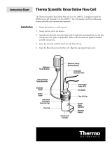
Analyzer Description
Figure 8. Analyzer Description
The upper portion of the enclosure contains the Display and
Electronics necessary for operation. The connection for data
and power are also located in the upper portion. The Display
contains both the input and communication cards for
recording the measurement and sending the data to the
central computer system. The TRO sensor and the
temperature sensor are wired into the input card inside the
display (TRO Card). The communication card comes
pre-wired (communication cable to pump controller board).
The analog data communication (4-20 mA) is wired by the
installer as needed into the TRO Card. For details see
Wiring Diagram. The lower portion contains the fluidic
component required for measurement, reagent storage and
sample connection.
Sample Loop
Sample inlet is located on the left side of the instrument.
Sample return and drain connections are made on the bottom
side of the instrument. The sample inlet and sample return
fittings on the bottom of analyzer require 1/4" OD LLDPE
tubing. The measured sample drain fitting at the bottom of the
analyzer requires 1/8" OD FEP tubing.
The sample loop is used to obtain water from the sample
water and return water to drain through a fast loop. This
sample loop is used to enhance response time and to
maintain a fresh sample for the analyzer to draw off
analytically accurate sample volumes for measurement. An
optical sensor located in the sample loop automatically
activates the analyzer for on-demand, real-time results and
enables minimum consumption of reagent.
Note: The enclosure drain produces no waste under normal
use. However, in the event of spills or leaks, some waste may
be produced. The analyzer is shipped with all of the internal
Electronics Enclosure
Sample Pump
Reagent Pump
Fast Loop Drain Connection
Fluid Sensor Housing
Sample Inlet Connection
Pressure Regulator
3 Way Valve
Fast Loop Drain Grommet
Reagent Holder
Reagent Connection
Measurement Cell
Measured Sample Drain
User Interface Module
Warning: It is recommended that an external
sample shut off valve is installed.
Each analyzer MUST have its own drain tube
vented to atmosphere.

7070iX TRO Analyzer Analyzer Installation | 15
tubing attached. Before starting up the instrument, verify that
the tubing lines are secured.
TRO measurement sensing electrode
The TRO measurement electrode is a combination style
electrode consisting of a platinum sensing element and an
iodide reference element. A differential potential is developed
across these elements relative to the presence and
concentration of iodine in the sample stream. This potential
difference signal read by the analyzer in the form of a millivolt
signal which is then processed to obtain the TRO
concentration.
Automatic Temperature
Compensation (ATC)
The temperature sensor is integrated into the TRO Flow Cell
and is a resistive element type sensor (30 Kohm thermistor).
The temperature signal is passed to the analyzer to provide
the sample stream temperature. Automatic compensation
software adjusts the resulting measurement to reflect the
value which would result if the sample was at calibration
temperature.
Reagent
A TRO reagent is used to enhance and stabilize the
measurement in a variety of Dissolved Organic Carbon (DOC),
Particulate Organic Carbon (POC) and slit conditions found in
different cooling water matrix. The reagent is easily installed or
replaced with quick connect tube connector and is replaced
after approximate 80 hours of active chlorinating or
discharging operations.

16 | Startup and Operation 7070iX TRO Analyzer
Startup and Operation
Before starting operation of your Orion 7070iX Total Residual
Oxidant Analyzer, please ensure the following:
• Reagent is properly connected.
• Drain and sample lines are connected and sample is
available.
• The reagent has been primed. If not, prime the reagent
and ensure the reagent line has been filled.
Placing the TRO Analyzer
into Service
Your TRO Analyzer is now ready for routine operation. To
place the analyzer into routine service, make sure the 3-way
valve points to the left. When the analyzer detects sample
water into the analyzer, the analyzer will start running
automatically. If the sample flow is stopped, the analyzer will
stop running automatically until the sample flow is resumed.
To extend reagent life, users are strongly recommended to
shut off the sample to the analyzer when no measurement is
needed. The user can also control run/stop functionality of the
analyzer by using either interval mode or remote start mode.
The TRO Analyzer is designed to run unattended, analyzing
sample and self-cleaning/flushing the measurement cell while
it is running. All measurement parameters have been
pre-programmed at the factory. Consequently, the analyzer is
prepared for routine operation once the startup procedures
have been completed.
Reagent Installation
Follow the steps to install the reagent.
1. Open the outlet of the cardboard box of the reagent
package.
2. Place the reagent box onto the reagent shelf with the
dispensing spout pointed upwards.
3. Push the gray / blue cap down onto the dispensing spout
of the reagent bag and turn clockwise to secure.
4. Flip over the reagent box, making sure the reagent flows
into the tubing and then reinsert the box back into the
reagent holder. Secure the box by using the black strap.
Note: Take care to ensure there is no leaking by aligning the
threads of the cap with bag threads. A click is felt when cap is
locked in place.
5. Ensure the reagent is fully primed by running the Prime
two times (initial instrument install only) to fill the volume
of the transfer tube.
6. Inspect the reagent transfer tubing to be sure that it is
filled with reagent. Gentle tapping can move air bubbles if
they occur. It is important to the accuracy of reagent
delivery that no air bubbles are present in the transfer
tubing.
7. Installation is now complete.
Instrument Operation Modes
The setup menu allows the user to run the Orion 7070ix Total
Residual Oxidant Analyzer in different modes.
To set the operation mode:
Select Menu > Setup > Channel 1 > Operating Mode
Four options are available:
Continuous mode: The TRO Analyzer will run continuously
and readings on the screen will be updated every 2 seconds.
Interval mode: The TRO Analyzer will run at user defined
intervals (from 5 minutes to 30 minutes, adjustable in 1minute
increments). The reading on the screen will be updated based
on the user defined interval. The TRO analyzer automatically
starts running at the last two minutes of each interval period,
and reports measurement results for this interval and then
stops measurement until the next interval period. The last
measurement results will remain on the screen with “last read
xx minutes”.
Remote mode: The TRO Analyzer can be remotely triggered
to start and stop measurement though an input relay. When
the analyzer is remotely started, the analyzer will run
continuously and update the measurement results every
2 seconds until remotely stopped by the user.
Scheduled Mode: The TRO Analyzer can start measuring
automatically at a scheduled starting time and stop the
analysis at a scheduled stopping time. The user can setup
“Start / Stop” time frames on the Operating Mode screen.
/