Thermo Scientific Orion 2111LL User manual
- Category
- Measuring, testing & control
- Type
- User manual


ROSS and the COIL trade dress are trademarks of Thermo Fisher Scientific Inc.
AQUAfast, Cahn, ionplus, KNIpHE, No Cal, ORION, perpHect, PerpHecT, PerpHecTion, pHISA, pHuture, Pure Water, Sage, Sensing the Future, SensorLink,
ROSS, ROSS Ultra, Sure-Flow, Titrator PLUS and TURBO2 are registered trademarks of Thermo Fisher .
1-888-pHAX-ION, A+, All in One, Aplus, AQUAsnap, AssuredAccuracy, AUTO-BAR, AUTO-CAL, AUTO DISPENSER, Auto-ID, AUTO-LOG, AUTO-READ,
AUTO-STIR, Auto-Test, BOD AutoEZ, Cable-Free, CERTI-CAL, CISA, DataCOLLECT, DataPLUS, digital LogR, DirectCal, DuraProbe, Environmental Product
Authority, Extra Easy/Extra Value, FAST QC, GAP, GLPcal, GLPcheck, GLPdoc, ISEasy, KAP, LabConnect, LogR, Low Maintenance Triode, Minimum Stir
Requirement, MSR, NISS, One-Touch, One-Touch Calibration, One-Touch Measurement, Optimum Results, Orion Star, Pentrode, pHuture MMS, pHuture
Pentrode, pHuture Quatrode, pHuture Triode, Quatrode, QuiKcheK, rf link, ROSS Resolution, SAOB, SMART AVERAGING, Smart CheK, SMART STABILITY,
Stacked, Star Navigator 21, Stat Face, The Enhanced Lab, ThermaSense, Triode, TRIUMpH, Unbreakable pH, Universal Access are trademarks of
Thermo Fisher .
Guaranteed Success and The Technical Edge are service marks of Thermo Fisher .
PerpHecT meters are protected by U.S. patent 6,168,707.
PerpHecT ROSS are protected by U.S. patent 6,168,707.
ORION Series A meters and 900A printer are protected by U.S. patents 5,198,093, D334,208 and D346,753.
ionplus electrodes and Optimum Results solutions are protected by US Patent 5,830,338.
ROSS Ultra electrodes are protected by US patents 6,793,787.
Orion ORP Standard is protected by US Patent 6,350,367.
Orion NoCal electrodes with stabilized potential patent pending.
© 2007 Thermo Fisher Scientific Inc. All rights reserved. All trademarks are the property of Thermo Fisher Scientific Inc. and its subsidiaries.
The specifications, descriptions, drawings, ordering information and part numbers within this document are subject to change without notice.
This publication supersedes all previous publications on this subject.

1
Thermo Scientific Orion 2111LL Sodium Monitor User Guide
ROSS and the COIL tradedress are trademarks of Thermo Fisher Scientific Inc. US Patent 6,793,787
Table of Contents
Chapter I
General Information............................................ I-1
Introduction .............................................I-1
Features and Benefits.......................................I-2
Principles of Operation.....................................I-3
Principles of Calibration ....................................I-5
Fluidics Diagram..........................................I-7
Glossary ................................................I-8
Chapter II
Instrument Preparation . ........................................II-1
Unpacking the Instrument ..................................II-1
Mounting and Plumbing Instructions . . . . . . . . . . . . . . . . . . . . . . . . . .II-2
Electrical Wiring..........................................II-4
Safety Requirements .....................................II-4
Warning Labels and Locations ..............................II-5
Wiring the Instrument .....................................II-6
Terminal Assignments......................................II-8
Installation of Reagent & Diffusion Tubing. . . . . . . . . . . . . . . . . . . . . .II-9
Conditioning & Installation of New Sodium Electrode. . . . . . . . . . . .II-13
Installation of ATC probe ..................................II-13
Installation of New Reference Electrode . . . . . . . . . . . . . . . . . . . . . . .II-14
Chapter III
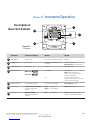
Instrument Operation..........................................III-1
Description of Basic Controls . . . . . . . . . . . . . . . . . . . . . . . . . . . . . . . III-1
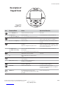
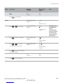
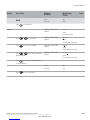
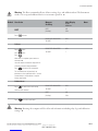
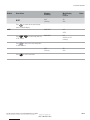
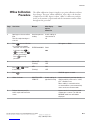
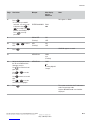
Description of Keypad Icons................................III-2
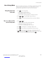
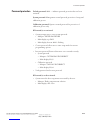
Use of Setup Mode .......................................III-3
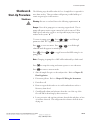
Shutdown & Start-Up Procedure . . . . . . . . . . . . . . . . . . . . . . . . . . . III-30
Chapter IV
Calibration...................................................IV-1
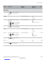
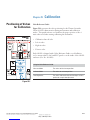
Positioning of Valves for Calibration . . . . . . . . . . . . . . . . . . . . . . . . . . IV-1
Flow Cell Operation ......................................IV-2
Rinsing the Flow Cell .....................................IV-3
Air Regulation...........................................IV-4
Before Performing DKA ...................................IV-5
Performing DKA Calibration ...............................IV-6
Calibration At Custom Concentrations Using DKA . . . . . . . . . . . . . IV-13
Span Check Procedure....................................IV-14
Offline Calibration Procedure..............................IV-15

2
Thermo Scientific Orion 2111LL Sodium Monitor User Guide
ROSS and the COIL tradedress are trademarks of Thermo Fisher Scientific Inc. US Patent 6,793,787
Chapter V
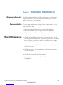
Instrument Maintenance. . ......................................V-1
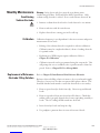
Weekly Maintenance.......................................V-1
Monthly Maintenance......................................V-2
Yearly Preventative Maintenance . . . . . . . . . . . . . . . . . . . . . . . . . . . . . .V-5
Chapter VI
Troubleshooting ..............................................VI-1
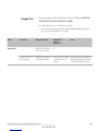
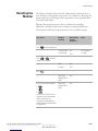
Diagnostics Mode . . ......................................VI-1
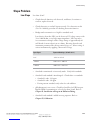
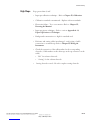
Slope Problems . .........................................VI-9
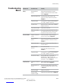
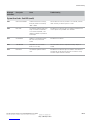
Troubleshooting Matrix...................................VI-11
Error/Event Codes.......................................VI-14
Resetting the Monitor....................................VI-17
Serial Number and Software Revision . . . . . . . . . . . . . . . . . . . . . . . . VI-18
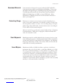
Service and Repair.......................................VI-19
Chapter VII
Customer Service . . ...........................................VII-1
Notice of Compliance. ...................................VII-1
Declaration of Conformity ................................VII-2
Terms and Conditions....................................VII-3
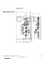
Appendix .....................................................A-1
Mounting Dimensions .....................................A-1
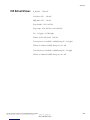
ISE Default Values ........................................A-2
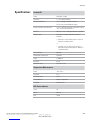
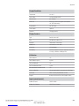
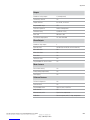
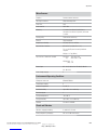
Specifications ............................................A-3
Ordering Information......................................A-7
Recommended Consumables for Annual Operation . . . . . . . . . . . . . .A-10
Recommended Field Replaceable Space Parts . . . . . . . . . . . . . . . . . . .A-10
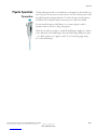
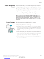
Pipette Operation ........................................A-11
Pipette Techniques .......................................A-12

I-1
Thermo Scientific Orion 2111LL Sodium Monitor User Guide
ROSS and the COIL tradedress are trademarks of Thermo Fisher Scientific Inc. US Patent 6,793,787
Chapter I General Information
This manual covers operation, maintenance and troubleshooting for the
Thermo Scientific Orion 2111LL sodium monitor, which incorporates
state of the art technology designed for ease of use while offering the lowest
limit of detection available.
Monitoring the sodium ion content of steam and water circuits to
produce accurate and reproducible results requires a very well designed
and maintained system. The system must optimize the fluidic design with
the sensing technology to enable very low-level (ppb) measurement of the
contaminants as well as measuring across the linear range of the analyzer.
The Orion 2111LL sodium monitor meets all of the criteria for accurate
and dependable sodium monitoring and more. The 2111LL incorporates
patented Orion technologies including:
• ROSS® and ROSS Ultra® electrodes
• Newly developed flow cell design
• Marquee help screen
• Orion pump-less reagent addition and DKA calibration system
Orion 2111LL ionplus® Low Level Sodium Monitor
• Power
• Semiconductor
• Chemical & Petrochemical
• Pulp & Paper
• Ultra pure water
• Boiler feed water
• Drum boiler water
• Ion exchange breakthrough
• Steam
• R/O system
Introduction
Markets:
Applications:

I-2
General Information
Thermo Scientific Orion 2111LL Sodium Monitor User Guide
ROSS and the COIL tradedress are trademarks of Thermo Fisher Scientific Inc. US Patent 6,793,787
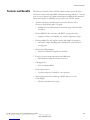
The Thermo Scientific Orion 2111LL sodium monitor meets all of the
criteria for accurate and dependable sodium monitoring and more. Our 30
years of sensor expertise in sodium measurements combined with patented
Orion technologies are skillfully incorporated in the 2111LL system.
• Accurate and precise measurements even at the lowest levels of
detection (range 0.001 ppb to 10 ppm):
• Reliable, low level measurements and wide range with selectable
resolution.
• Patented ROSS Ultra® reference and ROSS® sensing electrodes:
• Superior accuracy and stability over a wider temperature range.
• Patent-pending flow cell with air stirring and sample air transport:
• Automatic sample handling and contamination control with no
moving parts.
• Patented scrolling marquee:
• Intuitive menu-driven digital user interface.
• Data log of previous measurements and calibration:
• Measurement, calibration and error history.
• Self diagnostics:
• Ease of maintainability.
• Password protection:
• Security and peace of mind for your operation.
• Auto-ranging electronics with large, backlit and easy to read
LCD display:
• Monitor determines best range.
Features and Benefits

I-3
General Information
Thermo Scientific Orion 2111LL Sodium Monitor User Guide
ROSS and the COIL tradedress are trademarks of Thermo Fisher Scientific Inc. US Patent 6,793,787
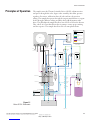
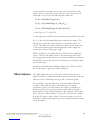
The sample enters the Thermo Scientific Orion 2111LL sodium monitor
and passes through inlet valve, bypass valve assembly, inlet filter, pressure
regulator, flow meter, calibration shut-off valve and into the restrictor
tubing. The sample then passes through the reagent manifold into a reagent
bottle through a diffusion tubing assembly where pH adjustment takes
place. The pH-adjusted sample then flows into the flow cell via the diverter
valve, where air is introduced from the air pump to ensure proper mixing
and fast response. The sample then flows into an atmospheric drain.
Principles of Operation
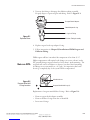
Monitor
1 2 3 4 5
Power
4-20mA Output
Air Pump
Reference Solution
Main Feed
Cal
Sample
Inlet Valve
Needle Valve
& Filter
Regulator
Valve
Safety Drain
for DIPA overflow
Cal Shutoff
Valve
3 way
Right Valve
Restrictor Tubing
3 way
Left Valve
Diverter Valve
Recirculation Block
Flowcell Block
Measure Level
Calibration Level Air Filter
Pressurizes flowcell
to initiate siphoning
Calibrate
Calibrate
Flowmeter
Mix (measure)
Calibration
Port
DIPA
Reagent Bottle
Reagent Manifold
Diffusion Tubing
Drain
Sense
REF
TEMP
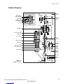
Fluid Path
Fluid Restrictor Tubing
Electric
Air Path
Reference Solution Path
DIPA Overflow Path
Diffusion Tubing
K E Y
Diverter Valve Positions
Calibration Mode
Sample/Measure Mode
Calibrate
Valve Position
Siphon/
Measure
Calibrate
Valve Position
Mix/
Measure
Figure I-1
Orion 2111LL Schematic

I-4
General Information
Thermo Scientific Orion 2111LL Sodium Monitor User Guide
ROSS and the COIL tradedress are trademarks of Thermo Fisher Scientific Inc. US Patent 6,793,787
The sensing electrode responds logarithmically to changes in the sodium
ion concentration. This response is described by the Nernst equation:
E = Eo + 2.3 (RT/nF) log (C/Ciso)
Where:
E = measured electrode potential, mV
Eo = potential, when C equals Ciso, mV
R = ideal gas constant
T = temperature of sample, degrees K
n = valence of ionic species (+1 for sodium ion)
F = Faraday’s constant
C = effective sodium ion concentration (activity)
Ciso = concentration (activity) of sodium ion where potential E is
temperature independent (isopotential point)
The above equation indicates that the measured potential varies with both
temperature and the concentration of the ion of the interest. In order to
eliminate error caused by fluctuations in sample temperature, the 2111LL
microprocessor constantly updates temperature corrections from data
supplied by the ATC probe.
From the Nernst equation, the theoretical response of a sodium ion-
selective electrode to a ten-fold change in concentration at 25 ˚C is
59.16 mV. This is referred to as the electrode slope (S). Most electrodes,
however, do not exhibit a theoretical slope. Therefore, the instrument is
calibrated to determine its actual value. Two standards are used to provide
information necessary for the microprocessor to compute the actual slope
and E0 for use during sample analysis.
In order to eliminate interference from hydrogen ions, which can become
significant when measuring low levels of sodium, the 2111LL adjusts
sample pH to approximately 11. This pH adjustment is accomplished by
the patented passive-diffusion process wherein the sample passes through
a length of tubing contained in the reagent bottle. The reagent diffuses
through the tube wall and mixes with the sample, raising sample pH to
approximately 11.

I-5
General Information
Thermo Scientific Orion 2111LL Sodium Monitor User Guide
ROSS and the COIL tradedress are trademarks of Thermo Fisher Scientific Inc. US Patent 6,793,787
Principles of
Calibration
Calibration procedures for an analytical instrument are important and must
be performed carefully. The calibration procedure used in the Thermo
Scientific Orion 2111LL is a variation of Double Known Addition (DKA)
using ROSS Ultra® electrode technology and patent-pending flow cell
technology in combination with the passive diffusion system. This method
has the distinct advantages of being fast, easy, and accurate.
Before calibration begins, the diverter valve is turned to divert flow from
the measure drain to the re-circ tube, allowing the flow cell to fill.
The two air valves serve dual purposes during the calibration sequence.
The first function is to stop the airflow through the sample, and redirect
the airflow to the headspace of the flow cell. Thus, the flow cell is filled
without causing air bubble disturbance in the sensing tube. The second
function ensures proper siphoning operation. The combination of these
functions provides an accurate volume for calibration.
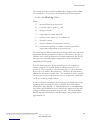
At the first step of the DKA calibration the actual concentration in the
sample is unknown. The instrument measures the potential (Es) and stores
this value in the microprocessor. A known amount of standard 1 solution
is added to the flow cell, which increases the concentration (Cs) with a
corresponding known amount (dC1). During this process, air is pumped
into the re-circ tube, thoroughly mixing sample and standard in a closed-
loop system. The new potential (E1) is measured and stored automatically
when stability is reached. Adding standard 2, preferably 10 times more
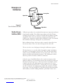
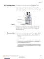
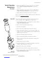
Siphon Tube
Siphon Drain
Sensing Tube
Double-Known
Addition (DKA)
Figure I-2
Flow Cell Volume for DKA

I-6
General Information
Thermo Scientific Orion 2111LL Sodium Monitor User Guide
ROSS and the COIL tradedress are trademarks of Thermo Fisher Scientific Inc. US Patent 6,793,787
concentrated than standard 1, increases the concentration (dC2) in the
sample reservoir. Again, the new potential (E2) is measured and stored
when stable. Now, we have the following three unknowns:
Es =Eo + S(Ts/298.15) log (Cs/Ciso)
E1 =Eo + S(T1/298.15) log [(Cs + dC1)/Ciso]
E2 =Eo + S(T2/298.15) log [(Cs+ dC1+ dC2)/Ciso]
S is the Slope at 25 ˚C (298.15 K)
T is the temperature in Kelvin, measured when the potential E is measured.
Es, E1, E2 have been determined during the calibration procedure. The
microprocessor solves these three equations, to obtain the values of S
and Eo. The calibration result is stored for use during online monitoring
to convert the measured potential and temperature in the sample into
concentration values in either ppm or ppb.
When the calibration is complete the flow cell drains as the sample flow
returns. The flow cell volume returns to the measurement level. After
allowing approximately 30 minutes for concentrated calibration solution to
be flushed from the system, the Orion 2111LL monitor can begin sample
measurement again.
In addition to Double-Known Addition (DKA), the 2111LL also allows
the user the ability to perform an offline calibration.
The offline calibration feature of the Orion 2111LL allows the user to
adjust the monitor to values determined by alternate methods used in their
laboratory such as elemental spectroscopy and ion chromatography.
It is essentially a one point calibration. To perform offline calibration,
a sample is taken from the bypass of the instrument; the sample
concentration value is stored in memory; the sample is analyzed by an
alternate method of choice; the previously stored reading is adjusted to
the lab method result; and the instrument is then returned to the analysis
mode. The term “offline calibration” refers only to the fact that a sample
from 2111LL bypass is taken “offline” for laboratory analysis; in fact, no
downtime is experienced during the procedure and the instrument remains
online throughout.
Offline Calibration

I-7
General Information
Thermo Scientific Orion 2111LL Sodium Monitor User Guide
ROSS and the COIL tradedress are trademarks of Thermo Fisher Scientific Inc. US Patent 6,793,787
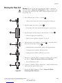
Fluidics Diagram
50
40
30
20
10
Scrolling Marquee
LCD Display
Warning Icon
Mode Indicator
Calibration
Shut Off
Valve
Mounting
Hole
Keypad
Left Air Valve
Flow Cell Reservoir
Siphon Tube
Sensing Tube
Flow Cell Block
Siphon Drain
Re-Circulation Tube
Measurement Drain
Diverter Valve
Inlet Valve
Reagent Bottle
Diffusion
Tubing
Assembly
Reagent
Bottle
Adapter
Assembly
Pressure
Regulator
Air Pump
Status Indicators
Bypass
Valve
Inlet
Filter
Flow Meter
Ref. Electrode
Filling Solution
Right Air Valve
Restrictor Tube
Assembly
Bottle
Bracket
Reagent
Manifold
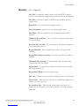
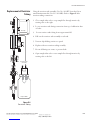
Figure I-3
Fluidics Diagram

I-8
General Information
Thermo Scientific Orion 2111LL Sodium Monitor User Guide
ROSS and the COIL tradedress are trademarks of Thermo Fisher Scientific Inc. US Patent 6,793,787
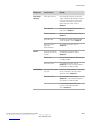
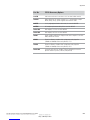
Refer to Figure I-3.
Inlet Valve – Accepts the sample stream via 1/4 inch NPTF connector.
The user must supply the sample with a pressure between 14 and 100 psig.
Inlet Filter – 60-micron stainless steel filter traps particulate matter in
sample stream.
Bypass Valve – Use to redirect flow in bypass system.
Pressure Regulator – Adjusts flow on incoming sample stream.
Flow Meter – Measures sample flow rate (40 mL/min nominal flow is
required).
Calibration Shut Off Valve – Use to stop flow of sample from flow meter
to restrictor tubing.
Restrictor Tube Assembly – Use in conjunction with pressure regulator to
lower downstream pressure.
Reagent Manifold – Directs sample flow in and out of reagent bottle
assembly.
Reagent Bottle Adapter Assembly – Connects reagent bottle assembly to
manifold.
Diffusion Tubing Assembly – Semi-permeable tubing through which
reagent diffuses into the sample.
Reagent Bottle – Contains water-soluble amine, which raises the sample
pH to approximately 11.
Reagent Bottle Bracket – Secures reagent bottle.
Flow Cell – Contains reference electrode, sample electrode, and ATC probe.
Diverter Valve – Allows the flow cell reservoir to fill during calibration by
forming a closed-loop system.
Re-circulation Tube – Tube through which sample (assisted by air) is
pumped into the flow cell – used to mix solution in a closed-loop during
calibration.
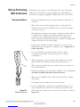
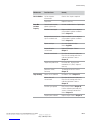
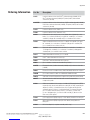
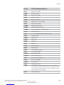
Glossary

I-9
General Information
Thermo Scientific Orion 2111LL Sodium Monitor User Guide
ROSS and the COIL tradedress are trademarks of Thermo Fisher Scientific Inc. US Patent 6,793,787
Sodium Electrode – Senses sodium ions in sample stream and produce an
electrical potential dependent on sample concentration.
Reference Electrode Filling Solution – Provides a constant reference
potential and completes the measurement circuit.
Reference Solution Bottle – Provides constant flow of electrolyte solution
through reference electrode for maximum stability.
ATC probe – Measures sample temperature and inputs data to
microprocessor for automatic temperature compensation (ATC).
Calibration Port – Allows introduction of standards to sample reservoir
during calibration.
Air Pump – Use to mix sample during both measurement and calibration.
Right Air Valve – Adjust airflow to flow cell. Controls airflow for mixing
sample.
Left Air Valve – Adjust airflow to flow cell. Controls airflow for siphon of
sample.
LCD Display – Provides digital readouts of concentration, temperature,
millivolts and error codes.
Keypad – Consists of five mode keys, four prompt indicator lights, two
scroll keys and one key for entering data. Mode and error indicators are
also incorporated on keypad.
Status Indicator – 2 LED lights that illuminate according to current status
of the instrument.
Green Light: indicates system is in correct working condition.
Yellow Light: indicates a warning, system in hold, or maintenance is
required.
Red Light: indicates something is seriously wrong.
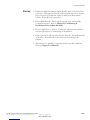
Note: When either the yellow or red LED is lit, there may be an entry
in the diagnostic menus indicating the error. Logging feature must be
initiated in the setup menu. Refer to Chapter III, Use of Setup Mode for
instructions. s

II-1
Thermo Scientific Orion 2111LL Sodium Monitor User Guide
ROSS and the COIL tradedress are trademarks of Thermo Fisher Scientific Inc. US Patent 6,793,787
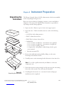
Chapter II Instrument Preparation
The Thermo Scientific Orion 2111LL sodium monitor has been assembled,
tested, and packaged with great care.
Report any obvious damage of shipping container to carrier and hold for
inspection. The carrier (not Thermo Fisher Scientific) is responsible for
any damage incurred during shipment.
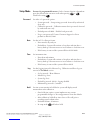
1. Open outer box. Remove top two foam corner support pieces.
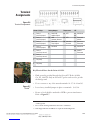
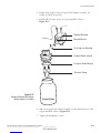
2. Open inner box. This box should contain (1) each of the following
items:
• 2111LL low level sodium monitor.
• ROSS® sodium electrode box.
• ROSS Ultra® reference electrode box.
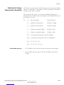
• Standards kit:
- (2) 2 oz. bottles of standard 1: concentration: 19.1 ppm Na+
- (2) 2 oz. bottles of standard 2: concentration: 192 ppm Na+
- (1) 2 oz. bottle of etching solution
-
(1) Options kit: cable glands, conduit fitting, fuse kit, green
screw terminal
• Instruction manual CD.
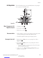
3. Remove the cardboard retaining shell by sliding over the entire
mounting board and the monitor.
4. Carefully remove entire mounting board with monitor from inner box.
Note: Do not lift or pull instrument by the fluidics or electronic
components. s
5. Unbolt the monitor from mounting board by removing the 4 mounting
bolts with a 9/16 wrench. These bolts may be discarded.
6. Carefully place the monitor at a convenient location until proper
installation can be completed.
Unpacking the
Instrument
Figure II-1
Unpacking the Instrument

II-2
Instrument Preparation
Thermo Scientific Orion 2111LL Sodium Monitor User Guide
ROSS and the COIL tradedress are trademarks of Thermo Fisher Scientific Inc. US Patent 6,793,787
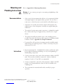
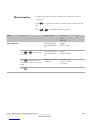
Refer to Appendix A1, Mounting Dimensions.
Warning: Do not connect power prior to mounting and plumbing of the
instrument. s
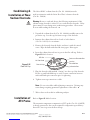
• Select a site for the instrument that allows it to be permanently bolted
with ample height for atmospheric drain operation. Be sure there is
ready access to both electronic controls and flow cell calibration port.
• A clearance of 15 inches (about 40 cm) must be allowed above the
calibration port. Insert the pipette vertically (not angled) during the
calibration.
• The analyzer location must permit connection to a plumbed in sample
line, a drain, and AC power supply and any connections for output
devices.
• The analyzer should be mounted as close to the sampling point as
possible, this ensures the fastest possible response to a changing sample
condition. Refer to Appendix A-4, Sample Conditions.
• For proper flow cell operations, instrument must be installed straight
and level upon its mounting location. Failure to level may cause poor
siphoning in flow cell.
1. Prepare mounting holes. Carefully lift the analyzer and bolt into place.
Do not lift the instrument by holding on to any of the plumbing or
fluid handling components.
2. Connect a waste line to the outlet of the instrument, which is 3⁄4 NPT
male. The waste line should be connected to a drain of sufficient
capacity, 0.5 inch (1.27 cm) OD is recommended.
3. Connect a sample line to the inlet of the instrument, which is 1⁄4 NPT
female. It is recommended that a shut-off valve be installed at the
sampling point.
4. The system must be mounted and leveled, vertically for proper
operation.
Mounting and
Plumbing Instructions
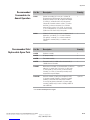
Recommendations
Instructions

II-3
Instrument Preparation
Thermo Scientific Orion 2111LL Sodium Monitor User Guide
ROSS and the COIL tradedress are trademarks of Thermo Fisher Scientific Inc. US Patent 6,793,787
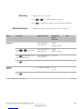
Additionally listed in Appendix A-3, Specifications.
Sample inlet connection – 1/4” NPTF. If particulate matter is present
in sample, pre-filtration is necessary. The 60-micron stainless steel filter
located after inlet valve will remove moderate amounts of particulates.
Flow rate – 40 mL/min (nominal).
Pressure – 8-100 psig. Consult Customer Support for Orion products* for
details on sample handling if pressure is outside range.
Temperature – Temperature must be between 5-40 ˚C.
Sodium level – Sodium levels are read directly in ppb or ppm, when
calibrated with Orion standards 1 and 2 (Cat. No. 181140).
Sample acidity – Sample acidity should not be more than 50 ppm CaCO3
equivalent. For higher sample acidity, contact Customer Support for
Orion products*.
* Customer Support for Orion Products
US & Canada: 800-225-1480
Dom. Fax: 978-232-6015
Int’l. Fax: 978-232-6031
www.thermo.com/water
Sample Requirements

II-4
Instrument Preparation
Thermo Scientific Orion 2111LL Sodium Monitor User Guide
ROSS and the COIL tradedress are trademarks of Thermo Fisher Scientific Inc. US Patent 6,793,787
Warning: Be sure to read and observe the following safety
recommendations! s
Warning icon provides important information that should be strictly
followed when using the unit for your own safety. Failure to follow these
instructions may result in injuries.
• Prior to wiring, a switch or circuit breaker for disconnecting the
instrument from power supply should be installed.
• It should be in close proximity to the monitor and with easy reach of
the operator.
• It should be marked as the disconnecting device for the monitor.
• To reduce the risk of shock hazard, disconnect power prior to opening
instrument.
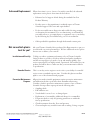
• Before connecting the instrument to the main, make sure that the
voltage lies within either range: 85-132V; 200 mA; or 170-264V; 100
mA; 50-60 Hz AC.
• Cutting off the power by disconnecting power source will not reset
the 2111LL. This unit incorporates a non-volatile memory and will
maintain calibration and settings after power failure. Battery power is
supplied to the display for the date and time functions.
• If a repair should be required, or to arrange a Return Material
Authorization, call Customer Support for Orion products at
1-800-225-1480 (Domestic toll free) or contact your authorized dealer.
• Installation and wiring of the 2111LL may only be carried out in
accordance with applicable local and national codes per this instruction
manual.
• Be sure to observe the technical specifications and input ratings.
Electrical Wiring
Safety Requirements
Recommendations

II-5
Instrument Preparation
Thermo Scientific Orion 2111LL Sodium Monitor User Guide
ROSS and the COIL tradedress are trademarks of Thermo Fisher Scientific Inc. US Patent 6,793,787
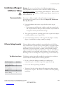
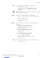
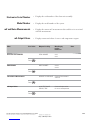
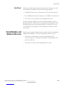
Warning Labels
and Locations
Warning: Provides important information that should be strictly followed
when using the unit for your own safety. Failure to follow these instructions
may result in injuries. s
Safety warning icons are used in two locations on the 2111LL.
• Faceplate. Refer to Figure II-2.
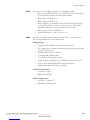
• Power supply. Refer to Figure II-3.
Replace fuse only with fuse of same rating.
Figure II-2
Faceplate
Fuse Holder
Fuse
Figure II-3
Power Supply

II-6
Instrument Preparation
Thermo Scientific Orion 2111LL Sodium Monitor User Guide
ROSS and the COIL tradedress are trademarks of Thermo Fisher Scientific Inc. US Patent 6,793,787
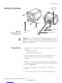
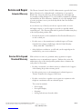
Wiring the Instrument
Warning: Be sure to read and observe the following requirements! If you
install the wrong fuse for your system, you could damage the instrument.
Make sure you select the correct fuse rating and discard the additional fuses
supplied in the fuse kit. s
• Options kit- fuses, cable glands, conduit fitting, and green screw
terminal.
• Phillips head screwdriver.
• 2 mm Blade flat-head screwdriver.
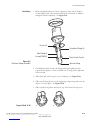
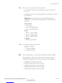
1. Open the faceplate: Loosen the four screws using a Phillips head
screwdriver. Electronics faceplate will open via the hinge pin
connection.
2. Remove one or two of the two unused cable glands as required for
wiring power cable or auxiliary connections. Power cable optional hole
locations in Figure II-4.
3. Select and install appropriate size cable gland or conduit fitting as
required.
4. Feed power cable through conduit or cable glands as appropriate.
Figure II-4
Electronics Enclosure
with Cable Glands
4 Compression
Screws
Hinge Pin
Power Cable
Hole Locations
Cable Glands
Electrode Cables
Required Tools

II-7
Instrument Preparation
Thermo Scientific Orion 2111LL Sodium Monitor User Guide
ROSS and the COIL tradedress are trademarks of Thermo Fisher Scientific Inc. US Patent 6,793,787
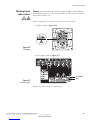
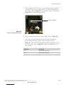
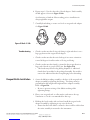
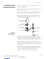
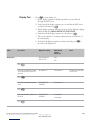
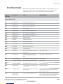
5. Wire the power cable to the green screw terminal connector from the
options kit. Select correct terminal for hot conductor depending on
line voltage. Refer to Figure II-5 for terminal connector location and
Figure II-3 for terminal wiring position.
6. Plug to terminal connector into power supply. Refer to Figure II-3.
7. Select the correct fuse from the fuse kit. Install by inserting fuse
in fuse holder and secure by twist and lock method. Refer to
Figure II-3. The fuses are clearly labeled with the appropriate voltages
for your system. Refer to Figure II-3. Refer to the table below for
fuse selection.
AC Voltage Fuse Rating
115V 200mA, 250V, Fast Acting
230V 100mA, 250V Fast Acting
Figure II-5
Terminal Connector Location
Terminal Connector
Page is loading ...
Page is loading ...
Page is loading ...
Page is loading ...
Page is loading ...
Page is loading ...
Page is loading ...
Page is loading ...
Page is loading ...
Page is loading ...
Page is loading ...
Page is loading ...
Page is loading ...
Page is loading ...
Page is loading ...
Page is loading ...
Page is loading ...
Page is loading ...
Page is loading ...
Page is loading ...
Page is loading ...
Page is loading ...
Page is loading ...
Page is loading ...
Page is loading ...
Page is loading ...
Page is loading ...
Page is loading ...
Page is loading ...
Page is loading ...
Page is loading ...
Page is loading ...
Page is loading ...
Page is loading ...
Page is loading ...
Page is loading ...
Page is loading ...
Page is loading ...
Page is loading ...
Page is loading ...
Page is loading ...
Page is loading ...
Page is loading ...
Page is loading ...
Page is loading ...
Page is loading ...
Page is loading ...
Page is loading ...
Page is loading ...
Page is loading ...
Page is loading ...
Page is loading ...
Page is loading ...
Page is loading ...
Page is loading ...
Page is loading ...
Page is loading ...
Page is loading ...
Page is loading ...
Page is loading ...
Page is loading ...
Page is loading ...
Page is loading ...
Page is loading ...
Page is loading ...
Page is loading ...
Page is loading ...
Page is loading ...
Page is loading ...
Page is loading ...
Page is loading ...
Page is loading ...
Page is loading ...
Page is loading ...
Page is loading ...
Page is loading ...
Page is loading ...
Page is loading ...
Page is loading ...
Page is loading ...
Page is loading ...
Page is loading ...
Page is loading ...
Page is loading ...
Page is loading ...
Page is loading ...
Page is loading ...
Page is loading ...
Page is loading ...
Page is loading ...
Page is loading ...
Page is loading ...
Page is loading ...
Page is loading ...
Page is loading ...
Page is loading ...
Page is loading ...
Page is loading ...
-
 1
1
-
 2
2
-
 3
3
-
 4
4
-
 5
5
-
 6
6
-
 7
7
-
 8
8
-
 9
9
-
 10
10
-
 11
11
-
 12
12
-
 13
13
-
 14
14
-
 15
15
-
 16
16
-
 17
17
-
 18
18
-
 19
19
-
 20
20
-
 21
21
-
 22
22
-
 23
23
-
 24
24
-
 25
25
-
 26
26
-
 27
27
-
 28
28
-
 29
29
-
 30
30
-
 31
31
-
 32
32
-
 33
33
-
 34
34
-
 35
35
-
 36
36
-
 37
37
-
 38
38
-
 39
39
-
 40
40
-
 41
41
-
 42
42
-
 43
43
-
 44
44
-
 45
45
-
 46
46
-
 47
47
-
 48
48
-
 49
49
-
 50
50
-
 51
51
-
 52
52
-
 53
53
-
 54
54
-
 55
55
-
 56
56
-
 57
57
-
 58
58
-
 59
59
-
 60
60
-
 61
61
-
 62
62
-
 63
63
-
 64
64
-
 65
65
-
 66
66
-
 67
67
-
 68
68
-
 69
69
-
 70
70
-
 71
71
-
 72
72
-
 73
73
-
 74
74
-
 75
75
-
 76
76
-
 77
77
-
 78
78
-
 79
79
-
 80
80
-
 81
81
-
 82
82
-
 83
83
-
 84
84
-
 85
85
-
 86
86
-
 87
87
-
 88
88
-
 89
89
-
 90
90
-
 91
91
-
 92
92
-
 93
93
-
 94
94
-
 95
95
-
 96
96
-
 97
97
-
 98
98
-
 99
99
-
 100
100
-
 101
101
-
 102
102
-
 103
103
-
 104
104
-
 105
105
-
 106
106
-
 107
107
-
 108
108
-
 109
109
-
 110
110
-
 111
111
-
 112
112
-
 113
113
-
 114
114
-
 115
115
-
 116
116
-
 117
117
-
 118
118


Thermo Scientific Orion 2111LL User manual
- Category
- Measuring, testing & control
- Type
- User manual
Ask a question and I''ll find the answer in the document
Finding information in a document is now easier with AI
Related papers
-
Thermo Scientific Orion 2295 User manual
-
-
-
-
-
-
-
-
Thermo Scientific CM-3CDEFT-32 User manual
-
Other documents
-
 Thermo Fisher Scientific Orion 2111LL Low Level Sodium Analyzer User guide
-
 Thermo Fisher Scientific Orion 2111XP Sodium Analyzer User guide
-
 Thermo Fisher Scientific Orion 2001FC Flow Cell Instruction Sheet
-
 Thermo Fisher Scientific Orion 2117XP User guide
-
 Thermo Fisher Scientific Orion 2117LL Low Level Chloride Analyzer User manual
-
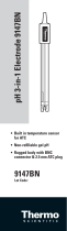 Thermo Fisher Scientific pH 3-in-1 Electrode 9147BN User guide
-
 Thermo Fisher Scientific Orion 2001SC ROSS pH Electrode User guide
-
 Thermo Fisher Scientific MIC-6 Multi Owner's manual
-
 Thermo Fisher Scientific EID-Orion 2111XP Sodium Analyzer User guide
-
OMNIPRO 220674 User manual


