CENTER SECTION ASSEMBLY
GENERAL INSTRUCTIONS:
1. Insert side plate assemblies into hitch center section. Refer to specific instructions for proper bolt location.
Insert the coiled end of fishwire through proper hole on rear side of center section and through access hole in
plate. Attach 1/4” bolt plate and 1/2 x 1-1/4 lg. carriage bolt as shown above. Pull fasteners through and loosely
install 1/2 hex lock nut. Repeat steps for each fastener. The spare tire may need to be lowered to install the hitch
center section. It will be replaced later.
2. Refer to the application chart to determine the correct installation for your vehicle. (Last page of each language)
FOR ALL INSTALLATIONS:
1. Torque all 3/8" nuts to 35 lb.ft. 5. Torque all 10mm CL10.9 hardware to 53 lb.ft.
2. Torque all 12mm nuts & bolts to 65 lb.ft. 6. Torque all 10mm Torx hardware to 60 lb.ft.
3. Torque all 7/16” hardware to 50 lb.ft. 7. Torque all 5/8” hardware to 100 lb.ft.
4. Torque all 1/2” hardware to 75 lb.ft. 8. Retighten the spare tire if it was loosened.
NOTE: Not all of the hardware will be used in every installation. Paint any bare metal to prevent rust.
TOOLS REQUIRED
3/4” SOCKET & WRENCH
11/16” SOCKET & WRENCH
9/16” SOCKET & WRENCH
15MM, 17MM SOCKET
18MM, 19MM SOCKET
21MM, 22MM SOCKET
TORQUE WRENCH
SAFETY GLASSES
TORX T50 WRENCH
SIDE PLATE ASSEMBLY
SEE SPECIFIC INSTRUCTIONS
FOR PROPER BOLT LOCATION
MUST INSTALL REAR SIDE BOLT FIRST
1/2” x 1.25 LG. CARRIAGE BOLT
1/4 x 1 x 2” BOLT PLATE
1/2 HEX LOCKNUT
ACCESS
HOLE
For Installation Assistance or Technical Help, Call 1-800-428-7303
TOP VIEW HITCH
FRONT BOLT IS
OUTBOARD ONE HOLE
ALL (4) BOLTS ARE REQUIRED
APPLY SPECIAL LOAD RATING
LABEL (110990)
PULL WIRE
(SUPPLIED)
WARNING: DO NOT LUBRICATE THREADS, BOLT FAILURE MAY
OCCUR DUE TO OVER TIGHTENING.
WARNING: DO NOT DRILL OR WELD TO THIS HITCH.
INSTALLATION INSTRUCTIONS
Product No.
37152
SMALL PARTS
PACKAGE 37620
IMPORTANT NOTES
USE ONLY REESE SUPPLIED OR APPROVED BOLTS, LOCKNUTS,
AND WASHERS TO INSTALL THIS HITCH
SMALL PICKUP
MULTI-FIT
You can take it with you.
PLYMOUTH, MICHIGAN
37152IN_C 04-05-06 PCN08678 © 2006 Cequent Towing Products Litho in USA

SIDE BRACKET LOCATION 1.
1/2” KNURL NECK BOLT
1/2 LOCK WASHER
1/2 HEX NUT
SIDE BRACKET LOCATION 2.
1/2” KNURL NECK BOLT
1/2 LOCK WASHER
1/2 HEX NUT
1. Loosely install Side Brackets on vehicle per specific instructions.
Align holes in side plate with side bracket as shown.
2. Install the 1/2” Knurl neck bolts, 1/2 lock washers, and 1/2 hex nuts.
3. First - Tighten Knurl neck bolts to 90 FT-LB to seat bolt, then loosen and
retighten to 75 FT-LB
4. Second - Tighten Side Bracket fasteners to proper specifications.
(Refer to general instructions on Page 1. for specs. )
5. Center receiver tube on vehicle and tighten center section fasteners to 75 LB-FT.
CENTER SECTION BOLTS
(Location varies per vehicle)
SIDE BRACKET
SIDE PLATE
BRACKET LOCATIONS
TOOLS REQUIRED
3/4"(19MM) SOCKET
SAFETY GLASSES
TORQUE WRENCH
CENTER SECTION BOLTS
(Location varies per vehicle)
SIDE PLATE
SIDE BRACKET
1. Loosely install Side Brackets on vehicle per specific instructions.
Align holes in side plate with side bracket as shown.
2. Install the 1/2” Knurl neck bolts, 1/2 lock washers, and 1/2 hex nuts.
3. First - Tighten Knurl neck bolts to 90 FT-LB to seat bolt, then loosen and
retighten to 75 FT-LB
4. Second - Tighten Side Bracket fasteners to proper specifications.
(Refer to general instructions on Page 1. for specs. )
5. Center receiver tube on vehicle and tighten center section fasteners to 75 LB-FT.
RECEIVER TUBE
RECEIVER TUBE

SIDE BRACKET LOCATION 4.
SIDE BRACKET LOCATION 3.
BRACKET LOCATIONS
TOOLS REQUIRED
3/4"(19MM) SOCKET
SAFETY GLASSES
TORQUE WRENCH
1/2” KNURL NECK BOLT
1/2 LOCK WASHER
1/2 HEX NUT
1/2” KNURL NECK BOLT
1/2 LOCK WASHER
1/2 HEX NUT
1. Loosely install Side Brackets on vehicle per specific instructions.
Align holes in side plate with side bracket as shown.
2. Install the 1/2” Knurl neck bolts, 1/2 lock washers, and 1/2 hex nuts.
3. First - Tighten Knurl neck bolts to 90 FT-LB to seat bolt, then loosen and
retighten to 75 FT-LB
4. Second - Tighten Side Bracket fasteners to proper specifications.
(Refer to general instructions on Page 1. for specs. )
5. Center receiver tube on vehicle and tighten center section fasteners to 75 LB-FT.
1. Loosely install Side Brackets on vehicle per specific instructions.
Align holes in side plate with side bracket as shown.
2. Install the 1/2” Knurl neck bolts, 1/2 lock washers, and 1/2 hex nuts as shown.
3. First - Tighten Knurl neck bolts to 90 FT-LB to seat bolt, then loosen and
retighten to 75 FT-LB
4. Second - Tighten Side Bracket fasteners to proper specifications.
(Refer to general instructions on Page 1. for specs. )
5. Center receiver tube on vehicle and tighten center section fasteners to 75 LB-FT.
CENTER SECTION BOLTS
(Location varies per vehicle)
SIDE BRACKET
SIDE PLATE
SIDE BRACKET
SIDE PLATE
CENTER SECTION BOLTS
(Location varies per vehicle)
RECEIVER TUBE
RECEIVER TUBE

INSTALLATION A
TOOLS REQUIRED
3/4"(19MM) SOCKET 1/2" DRILL
TORQUE WRENCH SAFETY GLASSES
1/2” THICK SPACER
WHEN NEEDED
1/2 X 2”
CARRIAGE BOLTS
1/4” BOLT PLATE
1/2” FLAT WASHER
1/2” LOCK WASHE
R
1/2” HEX NUT
USE THIS HOLE
FOR CENTER
SECTION ASSEMBLY
SIDE
BRACKET
FRAME
HOLE 1
HOLE 4
NOTE:
General assembly -
loosely assemble center section
(page 1);
loosely install side brackets on vehicle
(this page);
install center section assembly
(page 2-3);
tighten all fasteners to proper
specifications
(page 1).
82-96 FORD BRONCO (FULL SIZE)
1. Place the side brackets near the end of the frame, align rear edge of bracket with end
of frame. Place 1/2" thick spacers between the frame and holes 1 & 4. Clamp in place. Drill
1/2" holes into the frame using holes 1 & 4 as a guide. Insert a 1/2” carriage bolt with bolt plate down through the frame and into hole 1.
2. Thread a carriage bolt onto the pull wire. Place a bolt plate over the bolt. Push the free end of the wire over the top of the frame and
back down between the gas tank and the frame. Pull the wire through hole 4 and bring the bolt out through the hole. Install 1/2" flat
washers, lock washers, and nuts on all bolts.
3. For the '94 Bronco, move the hitch forward to clear the bumper and install the hitch at that location.
4. Install center section per SIDE BRACKET LOCATION 1. (See page 2.)
EXISTING HOLE
SOME MODELS
DRILLED HOLE
84-95 CARAVAN / VOYAGER / TOWN & COUNTRY:
1. Install 1/2" carriage bolts with bolt plates into the existing holes in the bottom
of the frame, using the large access hole in the bottom of the frame. Hold the
side brackets up to the frame, inserting the bolts into holes 1 & 4.
2. If the van is older than 1989, hole 4 will need to be drilled. After drilling hole 4,
remove the bracket. Screw a carriage bolt onto the pull wire. Place a bolt plate
over the bolt. Insert the free end of the pull wire into the access hole in the
frame. Bring it out through the hole that was just drilled. Pull the bolt down
through the hole. Unscrew the wire and repeat for the other side.
NOTE: Some models will require a small flange at the bottom end of the frame
to be bent up slightly. This will allow hitch to be installed in the correct
position.
3. Place the brackets over the bolts and install 1/2" flat washers, lock washers,
and nuts on the bolts.
4. Install center section per SIDE BRACKET LOCATION 1.
(See page 2.)
1986-99 DAKOTA LONG BED
1. Center the side brackets on frame near the end and align rear edge of bracket with end of frame.
Clamp side brackets in place. Using the holes in bracket as a guide, drill a 1/2" hole into
the frame at holes 1 & 4. Insert 1/2”
carriage bolts with 1/4” bolt plates down through the frame and into holes 1 & 4. Instal
l 1/2" flat washers, lock washers, and nuts on
the car
riage bolts. Remove clamps.
2. Some models require 1/2” spacers betwe
en frame and side bracket.
3. Instal
l center section per SIDE BRACKET LOCATION 1. (See page 2.)
92-99 CHEVROLET SUBURBAN, 95-99 TAHOE, 92-99 GMC YUKON, 92-94 FULL SIZE BLAZER, 92-99 GMC SUBURBAN
1. Lift the side brackets up to the frame. Install a 1/4" thick spacer on one of the 1/2" bolts. Insert the bolt down through the existing
hole in frame and hole 1. Install a 1/2" flat washer, lock washer, and hex nut on the bolt. Repeat for other side.
2. Using hole 4 as a guide, drill a 1/2" hole in the frame. Install a 1/4" thick spacer on a 1/2" bolt and insert i
t down through the frame
and hole 4. Instal
l a 1/2" flat washer, lock washer, and hex nut on the bolt. Repeat for other side.
3. Some models require 1/2” spacers betwe
en frame and side bracket.
4. Instal
l center section per SIDE BRACKET LOCATION 1. (See page 2.)
REFER TO SIDE BRACKET LOCATION INSTRUCTIONS FOR PROPER BOLT TIGHTENING SEQUENCE.

96-05 CARAVAN, VOYAGER,
& TOWN & COUNTRY
ACCESS HARDWARE
THROUGH END OF FRAME
AT BUMPER BRACKET
UNIBODY FRAME
BUMPER
BRACKET
DRILLED HOLE
1/2” SPACER**
& WASHER IF REQ’D
1/2 X 2”
CARRIAGE BOLTS
1/4” BOLT PLATE
1/2” FLAT WASHER
1/2” LOCK WASHER
1/2” HEX NUT
HOLE 2
INSTALLATION B
TOOLS REQUIRED
3/4”, 18mm, 19mm SOCKET
SAFETY GLASSES
1/2" DRILL TORQUE WRENCH
USE THIS HOLE
FOR CENTER
SECTION ASSEMBLY
HOLE 1
DRILLED
HOLE
M12 x 45mm HEX BOLT CL10.9
1/2” FLAT WASHER
1/2” LOCK WASHER
HOLE 3
**1996-2000 Grand Caravan
and Grand Voyager with
Long Wheel Base Do Not
Require Spacer Blocks
if frame and rear cross
member are flat.
EXISTING WELDNUT
INSTALL FORWARD
CARRIAGE BOLT FIRST
1/2” HEX NUT
NOTE:
General assembly - loosely assemble center section (page 1); loosely install side brackets on vehicle (this page);
install center section assembly (page 2-3); tighten all fasteners to proper specifications (page 1)
96-03 VOYAGER,1996-2005 CARAVAN, & TOWN & COUNTRY (EXCEPT STOW&GO SEAT OPTION)
1.Remove the rearmost existing 12mm hex bolt from bottom of frame, both sides.
NOTE: Do not remove the forward 12mm bolt.
2. Raise side brackets into position, aligning hole 2 in bracket with existing weldnut. Place (1) 1/2” spacer between
side bracket and frame at hole 2. (**See note)
3. Loosely install supplied 12mm CL10.9 hex bolts, 1/2 lock washers, and flat washers into weldnuts.
4. Using the rearmost end of hole 1 and the center of hole 3 in side bracket as a guide, drill a 1/2" hole into the
frame at holes 1 & 3.
5. Place (1) 1/2” spacer between side bracket and frame at hole 3. (**See note)
6. Use pull wire to install 1/2” x 2 carriage bolts with 1/4” bolt plates through access at end of frame and
into drilled holes. NOTE: Install forward carriage bolt first.
7. Loosely install 1/2" flat washers, lock washers, and nuts on the carriage bolts.
8. Raise center section into position and install per SIDE BRACKET LOCATION 1. (See page 2)
REFER TO SIDE BRACKET LOCATION INSTRUCTIONS FOR PROPER BOLT TIGHTENING SEQUENCE

INSTALLATION C
1/2 x 2”
CARRIAGE BOLTS
1/2” FLAT WASHER
1/2” LOCK WASHER
1/2” HEX NUT
1/4” BOLT PLATE
(If the 1-1/8” dia. hole is present,
then use the 1/4 x 1-1/2 x 3 Block
for this attachment.)
VEHICLE FRAME
DRILLED HOLE
TOOLS REQUIRED
3/4"(19MM) SOCKET
1/2" DRILL
TORQUE WRENCH
SAFETY GLASSES
1/2” THICK SPACER
WHEN NEEDED
USE THIS HOLE
FOR CENTER
SECTION ASSEMBLY
1983-2004 CHEVROLET S-10/GMC SONOMA - LONG BED / 1987-2004 NISSAN PICK-UP W/56” BEDS
1. Center the side brackets on frame and align hole 2 under large hole (if present) near end of frame.
(Note: Some models require 1/2” spacers between side bracket and frame.)
2. Insert 1/2” carriage bolts with 1/4 x 1-1/2 x 3” bolt plates down through large hole in frame and into hole 2 in side
bracket. Use 1/2” spacers if necessary.
3. Install 1/2" flat washers, lock washers, and nuts on the carriage bolts.
4. Using hole 4 in bracket as a guide, drill a 1/2" hole into the frame at hole 4.
5. Install 1/2” carriage bolts with 1/4” bolt plates through drilled hole.
6. Install 1/2" flat washers, lock washers, and nuts on the carriage bolts.
7. Install center section per SIDE BRACKET LOCATION 1 - LOCATION 2 for Nissan pick-ups. (See page 2.)
**If large hole is not
present near end of frame:
8. Raise side brackets in approximate position shown and clamp in place. Using holes in side bracket as a guide,
drill 1/2” holes into frame at holes 2 & 4.
9. See steps 5 through 7 to finish installation.
DRILLED HOLE (ON SOME MODELS)
EXISTING LARGE HOLE (ON SOME MODELS)
HOLE 4
HOLE 2
HOLE 1
NOTE:
General assembly - loosely assemble center section (page 1);
loosely install side brackets on vehicle (this page);
install center section assembly (page 2-3);
tighten all fasteners to proper specifications (page 1).
NISSAN PICK-UPS
USE THIS BRACKET
LOCATION
S-10/SONOMA PICK-UPS
& DODGE RAM CHARGER
USETHIS BRACKET
LOCATION
82-93 DODGE RAM CHARGER
1. Position the side brackets up to the frame with hole 1 under the rivet head. Clamp in place or mark the frame at
holes 2 and 4. Drill a 1/2" hole into the frame at holes 2 and 4.
2. Place a 1/2" thick spacer between the frame and holes 2 and 4. Thread a 1/2" carriage bolt onto the pull wire.
Place a bolt plate over the bolt. Push the free end of the pull wire through the end of the frame and bring it out
through the 1/2" mounting hole. Pull the bolt down through the hole. Unscrew the pull wire and repeat for the
other bolts.
3. Install 1/2" flat washers, lock washers, and nuts on the bolts.
4. Install center section per SIDE BRACKET LOCATION 1. (See page 2.)
REFER TO SIDE BRACKET LOCATION INSTRUCTIONS FOR PROPER BOLT TIGHTENING SEQUENCE

3/4"(19MM) SOCKET
1/2" DRILL
TORQUE WRENCH
SAFETY GLASSES
INSTALLATION E
TOOLS REQUIRED
NOTE:
General assembly - loosely assemble center section (page 1); loosely install side brackets on vehicle (this page);
install center section assembly (page 2-3); tighten all fasteners to proper specifications (page 1)
1/2” FLAT WASHER
1/2” LOCK WASHER
1/2” HEX NUT
USE THIS HOLE
FOR CENTER
SECTION ASSEMBLY
BUMPER
BRACKET
DRILLED HOLE
VEHICLE
FRAME
1/4” BOLT PLATE
1/2 X 2” CARRIAGE BOLT
12mm X 1.75 X 40mm
HEX BOLT
HOLE #3
USE THIS HOLE
AS A GUIDE TO
DRILL FOR
MAZDA PICK-UPS
HOLE #6
HOLE #5
1/2” FLAT WASHER
1/2” LOCK WASHER
12MM HEX NUT
90-93 MAZDA PICK-UP
1. Raise the brackets up to the frame with the bracket as far forward toward the front of the truck as possible. Do
not let the bracket rest upon the weld in the frame. Clamp in place.
2. Drill a 1/2" hole into the frame using hole 3 as a guide. Thread a 1/2" carriage bolt onto the pull wire and place a
bolt plate over the bolt. Push the free end of the pull wire into the open end of the frame and bring it out through
hole 3. Pull the bolt down through hole 3. Unscrew the wire.
3. Make sure hitch is level. Drill a 1/2" hole through the bumper bracket using hole 6 as a guide.
4. Install center section per SIDE BRACKET LOCATION 1. (See page 2.)
5. Insert a 12mm bolt from the outside, into hole. Install 1/2" flat washers, lock washers, and nuts on all bolts.
REFER TO SIDE BRACKET LOCATION INSTRUCTIONS FOR PROPER BOLT TIGHTENING SEQUENCE

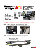
1. Lower the spare tire. Remove the bolts that hold the
bumper on the right side from the bottom of the frame.
Remove the nut clips from the frame. Remove the bumper
brace that goes to the corner of the bumper. You will need the
TORX T50 wrench to unbolt it from the bumper. (FOR 98-05 MODELS)
2. Drop the 1/2” carriage bolts and bolt plates through the holes in the
frame and hold the Right Hand Bracket up over the bolts with flat washers
between the frame and the bracket at all three bolting locations. Reinstall
the bumper bracket under the hitch bracket and install the 1/2” flat washers,
lock washers, and nuts. See the diagram above. Leave the nuts loose at this time.
3. Remove the left hand bumper brackets, nut clips, and the bumper corner brace.
4. Lift the Left hand bracket up above the the bumper bracket and place it under the frame.
Repeat step 2 for left hand bracket.
5. Install center section per BRACKET LOCATION 1. (See page 2.)
6. Re-attach the bumper braces. Bolt them into the slot in the center of the bumper. Retighten spare tire.
REFER TO SIDE BRACKET LOCATION INSTRUCTIONS FOR PROPER BOLT TIGHTENING SEQUENCE
83-06 RANGER & 94-06 MAZDA
98-03 RANGER/
MAZDA BUMPER
SUPPORT RELOCATION
INSTALLATION F
1/2 X 2” CARRIAGE BOLTS
1/2” FLAT WASHER
1/2” LOCK WASHER
1/2” HEX NUT
1/4” BOLT PLATE
TOOLS REQUIRED
3/4” SOCKET & WRENCH
18mm SOCKET
TORQUE WRENCH
SAFETY GLASSES
TORX T50 WRENCH
VEHICLE FRAME
BUMPER
BRACKET
USE THIS HOLE
FOR CENTER
SECTION ASSEMBLY
1/2” FLAT WASHERS
(Between Frame and Bracket)
NOTE:
General assembly - loosely assemble center section (page 1);
loosely install side brackets on vehicle (this page);
install center section assembly (page 2-3);
tighten all fasteners to proper specifications (page 1)
BEFORE
HITCH
INSTALLATION
AFTER HITCH
INSTALLATION

86-04 DODGE DAKOTA-SHORT BED
INSTALLATION G
5/8” FLAT WASHER
5/8” LOCK WASHER
5/8” HEX NUT
3/8” BOLT PLATE
-L -
BRACKET
DRILLED
HOLE
TOOLS REQUIRED
15/16" SOCKET
15MM SOCKET
19MM SOCKET
1/2" DRILL
5/8” DRILL
TORQUE WRENCH
SAFETY GLASSES
VEHICLE FRAME
BUMPER
BRACKET
5/8 X 2 HEX BOLT
12mm X 1.75 X 40mm
HEX BOLT
1/2” FLAT WASHER
1/2” LOCK WASHER
12mm HEX NUT
1/2” LOCK WASHER
12mm HEX NUT
1/2” LOCK WASHER
12mm HEX NUT
OPEN UP HOLE TO 5/8”
5/8” FLAT WASHER
1/2” FLAT WASHER
USE THIS HOLE
FOR CENTER
SECTION ASSEMBLY
1. Use the 5/8” drill to open the holes at the end of the frame to 5/8” diameter. Insert a 5/8” X 2 hex bolt with 3/8” bolt
plate through the hole at the end of the frame.
3. Lift the side brackets up to the frame and align hole #3 in side brackets with hex bolts. Place one 5/8” flat
washers between the frame and bracket on the hex bolts to space the side brackets down off the rivet in the
frame. See the diagram.
4. Install 5/8” flat washers, lock washers and nuts on the carriage bolts. Tighten the bolts so that the hitch is level.
5. Attach “L” brackets to the side brackets over holes 1 & 2 with two (2) M12 x 40mm hex bolts,
each side as shown.
6. Using the long slot as a guide, drill a 1/2” hole at far rearward end of slot through the
bumper brackets. Install M12 x 40mm hex bolts, flat washers, lock washers and nuts on the bolts.
7. Install center section per SIDE BRACKET LOCATION 1. (See page 2.)
FOR DAKOTA QUAD CAB - 2000-01
1. Remove mass-damper using 15mm socket. (Mass-damper is the round tube just forward of the bumper, suspended
on rubber mounts.)
2. Complete above steps (1-7)
3. Reinstall mass-damper.
REFER TO SIDE BRACKET LOCATION INSTRUCTIONS FOR PROPER BOLT TIGHTENING SEQUENCE
NOTE:
General assembly - loosely assemble center section (page 1); loosely install side brackets on vehicle (this page);
install center section assembly (page 2-3); tighten all fasteners to proper specifications (page 1)
HOLE 1 HOLE 2
HOLE 3
5/8” FLAT WASHER

INSTALLATION H
1/2” FLAT WASHER
1/2” LOCK WASHER
1/2” HEX NUT
1/2” THICK SPACER
WHEN NEEDED
DRILLED HOLE
TOOLS REQUIRED
3/4"(19MM) SOCKET
19MM SOCKET
1/2" DRILL
TORQUE WRENCH
SAFETY GLASSES
VEHICLE FRAME
BUMPER
BRACKET
1/2” LOCK WASHER
12mm HEX NUT
USE THIS HOLE
FOR NISSAN FRONTIER
CENTER SECTION ASSEMBLY
1/2” FLAT WASHER
1/2” LOCK WASHER
12mm HEX NUT
12mm X 1.75 X 40mm
HEX BOLT
1/2” LOCK WASHER
12mm HEX NUT
1/2 x 2” CARRIAGE BOLT
1/4” X 1-1/2” X 3”
BOLT PLATE
-L -
BRACKET
1/2” FLAT WASHER
HOLE 3
NOTE:
General assembly - loosely assemble center section (page 1); loosely install side brackets on vehicle (this page);
install center section assembly (page 2-3); tighten all fasteners to proper specifications (page 1)
87-04 NISSAN PICK-UP / FRONTIER 2 & 4 DOOR WITH 75” BEDS
1. Remove the bolt from the bottom of the frame, reverse its direction, and reinstall the bolt with the head on the bottom
of the frame. Position the side brackets up to the frame rearward of the bolt with a 1/2” spacer over hole 3.
2. Drill a 1/2” hole in the frame at hole 3. Install a 1/2” carriage bolt with 1/4 x 1-1/2 x 3” block down through the frame,
spacer and hole 3.
3. Attach the “L” brackets to the side brackets over holes 1 & 2 with two (2) M12 x 40mm hex bolts as shown.
4. Using the long slot as a guide, drill a 1/2” hole at far end of slot through the bumper brackets. Install M12 x 40mm
hex bolts, flat washer, lock washers and nuts on the bolts.
5. Install center section per SIDE BRACKET LOCATION 2. (See page 2.)
REFER TO SIDE BRACKET LOCATION INSTRUCTIONS FOR PROPER BOLT TIGHTENING SEQUENCE

84-96 JEEP CHEROKEE, XJ (WITHOUT FUEL TANK SHIELD AND EXISTING HARDWARE IN FRAME)
1. Remove the bolts that hold the muffler hanger. Move the hanger to the right and replace the left bolt
into the right hole. This is done to move the exhaust over for tailpipe clearance with the hitch.
2.Thread a 1/2” x 2 carriage bolt onto the pull wire. Place a 1/4 bolt plate over the bolt. Push the free
end of the wire into the opening at the end of the frame. Bring the wire out through the hole in the
rear of the frame. Pull the bolt down through the hole. Repeat for the other side.
3.Place the side brackets up to the rear of the frame. Install 1/2" flat washers, lock washers and nuts
on bolts.
4. Install center section per SIDE BRACKET LOCATION 1. (See page 2.)
INSTALLATION I
TOOLS REQUIRED
3/4"(19MM) SOCKET
1/2” DRILL
TORQUE WRENCH
SAFETY GLASSES
VEHICLE FRAME
1/2 x 2” CARRIAGE BOLT
1/2” FLAT WASHER
1/2” LOCK WASHER
1/2” HEX NUT
USE THIS HOLE
FOR CENTER
SECTION ASSEMBLY
1/4” BOLT PLATE
NOTE:
General assembly - loosely assemble center section (page 1);
loosely install side brackets on vehicle (this page);
install center section assembly (page 2-3);
tighten all fasteners to proper specifications (page 1)
86-97 FORD AEROSTAR (EXTENDED
)
1. Place the hitch up to the frame and as far rearward as possible. Drill 1/2" holes into the frame using
holes 1, 2 & 4 as a guide. Open up the access hole in the bot
tom of the frame to allow the 1/2"
carriage bolt to pass through. This hole is located farther forward in the frame.
2. Thread a 1/2" carriage bolt onto the pull wire and place a bolt plate over it. Push the free end of the
pull wire into the access hole and out through one of the drilled holes. Pull the bolt down through
the hole. Remove the wire and repeat for the remaining holes.
3. Install 1/2" flat washers, lock washers, and nuts on all bolts.
4. Install center section per SIDE BRACKET LOCATION 1. (See page 2)
REFER TO SIDE BRACKET LOCATION INSTRUCTIONS FOR PROPER BOLT TIGHTENING SEQUENCE

FOR 1997-2001 JEEP CHEROKEE
VEHICLES WITH
STEEL FUEL TANK SHIELDS:
1. Loosen the tailpipe clamp from the tailpipe.
2. Remove the 12mm bolts fastening the shield to the
chassis rails if present. Loosen the
remaining bolt in the tailpipe hanger bracket.
3. Lift the side brackets to the frame, with the
flange on the right side under the tailpipe hanger
bracket.
NOTE:
It may be necessary on some models to
bend the heat shield in so the hitch can be
installed. It may be necessary to open the holes
in shield with a 1/2” drill.
4. Install the supplied 12mm bolts with 1/2" lock
washers, and 1/2 flat washers. Snug up the bolts.
5. Install center section per
SIDE BRACKET LOCATION 2. (See page 2.)
6. Adjust the tailpipe for clearance.
Tighten the tailpipe clamp.
REFER TO SIDE BRACKET LOCATION
INSTRUCTIONS FOR PROPER BOLT
TIGHTENING SEQUENCE
INSTALLATION J
TOOLS REQUIRED
3/4"(19MM) SOCKET 19MM SOCKET
1/2” DRILL
TORQUE WRENCH SAFETY GLASSES
FOR 1997-2001 JEEP CHEROKEE
VEHICLES WITHOUT
STEEL FUEL
TANK SHIELDS:
1. Remove the two nuts holding the exhaust hanger
to the frame. Unscrew the rearmost stud out of
the frame, if present on passenger side.
Remove existing 12mm bolts from passenger side of vehicle.
2. Insert a 1/2” carriage bolt through 1/4” bolt plate and attach the
pull wire. Pull the bolt into position through the opening in the end
of the frame on Driver’s side. Start with the forward bolt hole first.
See the diagram above.
3. Lift the side brackets up to the frame. Loosely install 1/2” lock washers, flat washers, and nuts
on the carriage bolts. Install 12mm hex head bolts with lock washers and flat washers into the three
locations of the passenger side. For some vehicles, the third hole needs to be drilled.
If hole requires drilling, use the pull wire to install a 1/2” carriage bolt with 1/4 bolt plate through end of frame.
Loosely install 1/2 flat washer, 1/2 lock washer, and hex nut on carriage bolt. See the diagram above.
4. Install center section per SIDE BRACKET LOCATION 2. (See page 2.)
5. Reinstall the exhaust under the hitch bracket. Install the 12mm bolt with a 1/2” lock washer and flat washer through the exhaust bracket,
the hitch bracket, and into the frame. Replace the factory nut on the other stud if present.
REFER TO SIDE BRACKET LOCATION INSTRUCTIONS FOR PROPER BOLT TIGHTENING SEQUENCE
1/2” FLAT WASHER
1/2” LOCK WASHER
1/2” HEX NUT
VEHICLE FRAME
HOLE MAY HAVE TO BE DRILLED
ON SOME MODELS
EXISTING 12MM
BOLTS
(STUD MAY
BE PRESENT)
EXISTING NUT PLATE
IN FRAME
REMOVE EXISTING
12MM BOLTS
1/2” FLAT WASHER
1/2” LOCK WASHER
EXISTING
NUT PLATE
IN FRAME
VEHICLE FRAME
USE THIS HOLE
FOR CENTER
SECTION ASSEMBLY
12mm X 1.75 X 40mm
HEX BOLT
1/2 x 2” CARRIAGE BOLT
1/4” BOLT PLATE
* INSTALL THIS BOLT FIRST
USING THE PULL WIRE
INSERT CARRIAGE BOLT
AND BOLT PLATE THROUGH
END OF FRAME
USE THIS HOLE
FOR CENTER
SECTION ASSEMBLY
12mm X 1.75 X 40mm
HEX BOLT
LOCK WASHER
FLAT WASHER
NOTE:
General assembly - loosely assemble center section (page 1); loosely install side brackets on vehicle (this page);
install center section assembly (page 2-3); tighten all fasteners to proper specifications (page 1)
12mm X 1.75 X 40mm
HEX BOLT

INSTALLATION K
TOOLS REQUIRED
19MM SOCKET
3/4” SOCKET
1/2” DRILL
TORQUE WRENCH
SAFETY GLASSES
USE THIS HOLE
FOR CENTER
SECTION ASSEMBLY
1/2 x 2” CARRIAGE BOLT
1/2” FLAT WASHER
1/2” LOCK WASHER
12MM HEX NUT
1/4” BOLT PLATE
EXISTING STUDS IN FRAME
VEHICLE FRAME
DRILLED HOLE
HOLE #1
HOLE #2
HOLE #3
1/2” FLAT WASHER
1/2” LOCK WASHER
1/2” HEX NUT
NOTE:
General assembly - loosely assemble center section (page 1); loosely install side brackets on vehicle (this page);
install center section assembly (page 2-3); tighten all fasteners to proper specifications (page 1)
93-98 JEEP GRAND CHEROKEE
1. Place the side brackets over the studs that are fastened into the bottom of the frame. Use holes 2 & 3.
Install 1/2" flat washers, lock washers, and 12mm nuts on the studs.
2. Drill a 1/2" hole into the frame using hole 1 as a guide. Thread 1/2 x 2 car
riage bolt onto the pull wire
and place a 1/4 bolt plate over the bolt. Insert the free end of the pull wire into the top of the bumper
bracket. This is between the end of the frame and the bumper. Push it out through hole 1. Pull the bolt
down through the hole. Unscrew the pull wire. Install 1/2" flat washers, lock washers, and nuts on the
car
riage bolts.
3. Install center section per SIDE BRACKET LOCATION 1. (See page 2)
REFER TO SIDE BRACKET LOCATION INSTRUCTIONS FOR PROPER BOLT TIGHTENING SEQUENCE

INSTALLATION L
TOOLS REQUIRED
19mm SOCKET
TORQUE WRENCH
SAFETY GLASSES
VEHICLE FRAME
HEAT SHIELD
IF PRESENT
HOLE # 1
1/2” FLAT WASHER
1/2” LOCK WASHER
HOLE # 3
EXISTING
WELDNUTS
USE THIS HOLE
FOR CENTER
SECTION ASSEMBLY
NOTE:
General assembly - loosely assemble center section (page 1); loosely install side brackets on vehicle (this page);
install center section assembly (page 2-3); tighten all fasteners to proper specifications (page 1)
12mm X 1.75 X 40mm
HEX BOLT
12mm X 1.75 X 40mm
HEX BOLT
2002-06 JEEP LIBERTY
1. If vehicle is equipped with a fuel tank shield, remove the two rearmost 12mm bolts from each side.
2. Lift the side brackets up to the frame in orientation shown and align hole 1. in side bracket with the
rearmost weldnut. Loosely install the supplied 12mm hex bolts, lock washers, and flat washers
into existing weldnuts in frame.
3. Install center section per SIDE BRACKET LOCATION 3. (See page 3.)
REFER TO SIDE BRACKET LOCATION INSTRUCTIONS FOR PROPER BOLT TIGHTENING SEQUENCE

INSTALLATION M
TOOLS REQUIRED
3/4” SOCKET
9/16" SOCKET
1/2" DRILL
TORQUE WRENCH
SAFETY GLASSES
3/8” x 3” HEX BOLT
RUBBER MUFFLER
HANGER
3/8 HEX NUTS
USE THIS HOLE
FOR CENTER
SECTION ASSEMBLY
1/2 x 2” CARRIAGE BOLT
1/4” BOLT PLATE
1/2” FLAT WASHER
1/2” LOCK WASHER
1/2” HEX NUT
DRILLED HOLES
HOLE #1
HOLE #4
VEHICLE FRAME
NOTE: General assembly - loosely assemble center section (page 1); loosely install side brackets on vehicle (this page);
install center section assembly (page 2-3); tighten all fasteners to proper specifications (page 1)
84-90 FORD BRONCO II
1. Either bend the muffler hanger rod out of the way or cut it off with a saw.
2. Place the side brackets up to the rear of the frame. Using holes 1 and 4 as a guide, drill 1/2" diameter
holes into the frame.
3. Reaching up between the gas tank and the frame, install 1/2" carriage bolts and 1/4 bolt plates into
holes 1 and 4. Install 1/2" flat washers, lock washers, and nuts on the bolts.
4. Install center section per SIDE BRACKET LOCATION 1. (See page 2)
5. Remount the muffler hanger to the side of the hitch bracket, using 3/8” hex bolt through side bracket
and rubber hanger. Install two(2) 3/8” nuts on the bolt, use the second nut as a lock against the first
nut.
REFER TO SIDE BRACKET LOCATION INSTRUCTIONS FOR PROPER BOLT TIGHTENING SEQUENCE

INSTALLATION P
3/4” SOCKET
1/2” DRILL
TORQUE WRENCH
SAFETY GLASSES
TOOLS REQUIRED
1/2 x 2” CARRIAGE BOLT
1/4” BOLT PLATE
1/2” FLAT WASHER
1/2” LOCK WASHE
R
1/2” HEX NUT
USE THIS HOLE
FOR CENTER
SECTION ASSEMBLY
VEHICLE FRAME CROSSMEMBER
DRILLED HOLE
EXISTING HOLE
HOLE 4
HOLE 1
ACCESS HOLE
NOTE:
General assembly - loosely assemble center section (page 1); loosely install side brackets on vehicle (this page);
install center section assembly (page 2-3); tighten all fasteners to proper specifications (page 1)
1996-06 CHEVROLET/ GMC FULL SIZE VANS
1. Install 1/2” X 2” carriage bolt with a 1/4" bolt plate through access hole and into the rearmost existing hole
in the bot
tom of the frame, both sides. Raise the side brackets into position, lining up hole 1 in bracket with
carriage bolt. Loosely install a 1/2" flat washer, lock washer, and hex nut on the bolt. Repeat for other side.
2. Using hole 4 in side bracket as a guide, drill a 1/2" hole in the frame. Install a 1/2” x 2 carriage bolt with a
1/4” bolt plate through drilled hole. Install a 1/2" flat washer, lock washer, and hex nut on the bolt. Repeat
for the other side.
3. Install center section per SIDE BRACKET LOCATION 4. (See page 3.)
REFER TO SIDE BRACKET LOCATION INSTRUCTIONS FOR PROPER BOLT TIGHTENING SEQUENCE

INSTALLATION Q
TOOLS REQUIRED
11/16”, 19MM SOCKET
TORQUE WRENCH
SAFETY GLASSES TAPE
7/16 x 1-3/4”
CARRIAGE BOLT
USE THIS HOLE
FOR CENTER
SECTION ASSEMBLY
7/16” CONICAL WASHER
7/16” HEX NUT
1999-2003 FORD WINDSTAR - ALL MODELS
1. Loosely install the side plate assemblies into center section as shown. (See page 1.)
Note: Slide the side plate assemblies toward center.
2. Use pull wire to install two (2) 7/16” x 1-3/4 carriage bolts with 1/4” bolt plates through access hole and
into the two holes on the inside of the frame, both sides.
3. Place a 1/2” thick spacer on each carriage bolt. Apply a small piece of tape to spacer and carriage bolt
to prevent bolt from sliding into frame.
4. Raise center section assembly and line up the two rearmost top holes on side plate with the
carriage bolts on one side of vehicle and install side plate over carriage bolts.
NOTE: Use a jack stand to temporarily support center section assembly.
5. Loosely install 7/16” conical washers and hex nuts on bolts.
6. Install the other side plate over the two carriage bolts and loosely install 7/16” conical washers and hex nuts.
7. Use pull wire to install 7/16” carriage bolt with 1/4” bolt plate in access hole in bottom of frame. Then pull
carriage bolt back through the access hole which will be used to install the “L” bracket. (See Figure 2.)
8. Line up hole in “L” bracket with 7/16” carriage bolt and loosely install 7/16” conical washer and hex nut on bolt.
Using a 12mm x 40mm hex bolt (fully threaded), 1/2” flat washer, and 12mm hex nut,
attach “L” bracket to side plate as shown in figures 1 & 2 each side as shown.
9. Tighten fasteners to proper torque. (See page 1.)
REFER TO SIDE BRACKET LOCATION INSTRUCTIONS FOR PROPER BOLT TIGHTENING SEQUENCE
1/2” THICK SPACER
VEHICLE FRAME
FIGURE 1.
“L” BRACKET
12mm X 1.75 X 40mm
HEX BOLT
ACCESS HOLE
USE THIS HOLE
FOR CARRIAGE BOLT
1/2” FLAT WASHER
1/2” LOCK WASHER
12mm HEX NUT
1/4” BOLT
PLATE
ACCESS HOLE
NOTE:
General assembly - loosely assemble center section (page 1); install center section assembly (this page);
tighten all fasteners to proper specifications (page 1)
SIDE PLATE
ASSEMBLY
3500 LB. MAX GROSS TRAILER WT.
350 LB. MAX TONGUE WT.
WEIGHT CARRYING ONLY
DO NOT USE WITH SPRING BARS
DO NOT EXCEED TOW VEHICLE RATINGS
ACCESS HOLE

INSTALLATION R
TOOLS REQUIRED
11/16” SOCKET 3/4” SOCKET
19MM SOCKET 1/2” DRILL
TORQUE WRENCH
SAFETY GLASSES
TIN SNIPS
2001-04 FORD ESCAPE/MAZDA TRIBUTE - ALL MODELS (VEHICLES WITHOUT O.E.M. TRAILER HITCH)
1. Remove heat shield on 2002 and earlier models.
2. Use pull wire to install two (2) 7/16 x 1-3/4” carriage bolts with 1/4" bolt plates through access hole at end of frame and into
the two (2) rearmost existing holes, both sides.
3. Raise the side brackets into position, lining up hole 1 in bracket with rearmost carriage bolt. Loosely install a 7/16” conical
washers and hex nuts on the bolts. Repeat for other side.
NOTE:
Do not tighten carriage bolt at hole location 2 until heat shield is reinstalled. (Step 6)
4. Using hole 4 in side bracket as a guide, drill a 1/2" hole in the frame. Install a 7/16 x 1-3/4” carriage bolt with a 1/4” bolt plate
through access hole and into drilled hole. Place tapered block and 3/16” spacer between frame and bracket.
Install a 7/16" conical washer and hex nut on the bolt. Both Sides.
5. Install center section per SIDE BRACKET LOCATION 3. (See page 3.)
6. To trim heat shield, cut a 3/4” wide slot approximately 11” long as shown in picture. Drill 1/2” hole in shield 3-7/8” from existing
hole in shield. Temporarily remove nut and washer from center carriage bolt. Reinstall heat shield around bracket. The center
carriage bolt should line up with drilled hole in heat shield.
Reinstall 7/16” conical washer and hex nut.
VEHICLES EQUIPPED WITH O.E.M. TRAILER HITCH
1. Remove heat shield on 2002 and earlier models.
2. Enlarge forward slot in bottom of frame to fit the 1/4” x 1 x 2” bolt plates, both sides.
3. Raise the side brackets into position, lining up hole 1 in bracket with rearmost existing weldnut. Loosely install 12mm hexbolt
with 1/2” lock washer and flat washer, both sides as shown.
4. Using holes 2 and 4 in side bracket as a guide, drill a 1/2” hole in the frame. Use pull wire to install 7/16 x 1-3/4 carriage
bolts with 1/4” bolt plates through access hole and into drilled holes.
Install a 7/16" conical washer and hex nut on the bolt. Both Sides.
NOTE:
Do not tighten carriage bolt at hole location 2 until heat shield is reinstalled. (Step 6 above)
5. See steps 5 & 6 above for final installation information.
REFER TO SIDE BRACKET LOCATION INSTRUCTIONS FOR PROPER BOLT TIGHTENING SEQUENCE
USE THIS HOLE
FOR CENTER
SECTION ASSEMBLY
7/16 x 1-3/4”
CARRIAGE BOLT
1/4” BOLT PLATE
7/16” CONICAL WASHER
7/16” HEX NUT
INSTALLATION WITH
EXISTING O.E.M. HITCH
INSTALLATION WITHOUT
EXISTING O.E.M. HITCH
HOLE 1
HOLE 2
HOLE 4
ACCESS HOLE
(Both Sides)
EXISTING
WELDNUT
(with O.E.M. Hitch)
DRILLED
HOLE
7/16 x 1-3/4”
CARRIAGE BOLT
1/4” BOLT PLATE
12mm X 1.75 X 40mm
HEX BOLT
LOCK WASHER
FLAT WASHER
TAPERED BLOCK
3/16” SPACER
DRILLED
HOLE
DRILLED HOLE
DRILLED HOLE
ACCESS
HOLE
HEAT SHIELD
NOTE: General assembly - loosely assemble center section (page 1); loosely install side brackets on vehicle (this page);
install center section assembly (page 2-3); tighten all fasteners to proper specifications (page 1)

INSTALLATION S
2001-04 CHEVROLET S-10/GMC S-15 SHORT BED (4 X 4 ONLY) AND CREW CAB
1998-2000 ISUZU HOMBRE SHORT BED (4 X 4 ONLY)
1. Disconnect ground wire from bottom surface of passenger’s side frame.
2. Raise side brackets into position. Place the mounting tab of brackets on top of frame as shown. Line up
hole 2 in bracket with large hole near end of frame.
3. Install 1/2” x 2” carriage bolt with 1/4” bolt plate down through hole 2 in side bracket and large hole
in end of frame. Place 1/4” x 1-1/2” x 3” block on carriage bolt and loosely install 1/2” flat washer,
lock washer and hex nut.
4. Measure 3-3/4” forward from the center of carriage bolt and drill a 1/2” hole in the bottom of frame.
NOTE: The drilled hole should line up with hole 3 of side bracket.
5. Install 1/2” x 2” carriage bolt with 1/4” bolt plate down through hole 3 in side bracket and drilled hole
in bottom of frame. Loosely install 1/2” flat washer, lock washer and hex nut, both sides.
6. Install center section per SIDE BRACKET LOCATION 3. (See page 3.)
7. Reattach ground wire to one of the unused holes in side bracket or plate.
REFER TO SIDE BRACKET LOCATION INSTRUCTIONS FOR PROPER BOLT TIGHTENING SEQUENCE
TOOLS REQUIRED
3/4” SOCKET
1/2” DRILL
TORQUE WRENCH
SAFETY GLASSES
USE THIS HOLE
FOR CENTER
SECTION ASSEMBLY
1/2” FLAT WASHER
1/2” LOCK WASHER
1/2” HEX NUT
DRILLED HOLE
1/2 x 2” CARRIAGE BOLT
1/4” BOLT PLATE
1/4” X 1-1/2” X 3”
BOLT PLATE
REMOVE
GROUND WIRE
HOLE 2
HOLE 3
VEHICLE FRAME
BUMPER
BRACKET
NOTE:
General assembly - loosely assemble center section (page 1); loosely install side brackets on vehicle (this page);
install center section assembly (page 2-3); tighten all fasteners to proper specifications (page 1)
3500 LB. MAX GROSS TRAILER WT.
350 LB. MAX TONGUE WT.
WEIGHT CARRYING ONLY
DO NOT USE WITH SPRING BARS
DO NOT EXCEED TOW VEHICLE RATINGS

1. Remove the existing 14mm bolt from the bottom of frame, both sides.
2. Raise the side brackets into position, lining up hole 2 in bracket with existing weldnut. Loosely reinstall
the 14mm bolts removed in step 1.
3. Using hole 4 in side bracket as a guide, drill a 1/2" hole in the frame. Install a 1/2” x 2 carriage bolt with a 1/4” bolt
plate through access hole and into drilled hole. Install a 1/2" flat washer, lock washer, and hex nut on the bolt.
Repeat for the other side.
4. Install center section per SIDE BRACKET LOCATION 4. (See page 3.)
REFER TO SIDE BRACKET LOCATION INSTRUCTIONS FOR PROPER BOLT TIGHTENING SEQUENCE
INSTALLATION T
2000-06 CHEVROLET SUBURBAN, TAHOE, GMC YUKON, YUKON XL
USE THIS HOLE
FOR CENTER
SECTION ASSEMBLY
1/2” FLAT WASHER
1/2” LOCK WASHER
1/2” HEX NUT
DRILLED HOLE
1/2 x 2” CARRIAGE BOLT
HOLE 2
HOLE 4
1/4” BOLT PLATE
VEHICLE FRAME
3/4” SOCKET
21MM SOCKET
22MM SOCKET
1/2” DRILL
TORQUE WRENCH
SAFETY GLASSES
TOOLS REQUIRED
CROSSMEMBER
ACCESS HOLE
EXISTING
WELDNUT
EXISTING M14 BOLT
NOTE:
General assembly - loosely assemble center section (page 1); loosely install side brackets on vehicle (this page);
install center section assembly (page 2-3); tighten all fasteners to proper specifications (page 1)
Page is loading ...
Page is loading ...
Page is loading ...
Page is loading ...
Page is loading ...
Page is loading ...
Page is loading ...
Page is loading ...
Page is loading ...
Page is loading ...
Page is loading ...
Page is loading ...
Page is loading ...
Page is loading ...
Page is loading ...
Page is loading ...
Page is loading ...
Page is loading ...
Page is loading ...
Page is loading ...
Page is loading ...
Page is loading ...
Page is loading ...
Page is loading ...
Page is loading ...
Page is loading ...
Page is loading ...
Page is loading ...
Page is loading ...
Page is loading ...
Page is loading ...
Page is loading ...
Page is loading ...
Page is loading ...
Page is loading ...
Page is loading ...
Page is loading ...
Page is loading ...
Page is loading ...
Page is loading ...
Page is loading ...
Page is loading ...
Page is loading ...
Page is loading ...
Page is loading ...
Page is loading ...
/