Page is loading ...

Champion Cooler
5800 Murray St.
Little Rock, AR 72209
www.championcooler.com
Portable Evaporative Cooler
Safety Rules
1. Unit must be in the Off Position and Unplugged from power receptacle when performing any mainte-
nance.
2. To reduce the risk of electric shock, plug unit into a properly grounded 120 Volt A.C., 60 Hz receptacle.
3. To reduce the risk of electric shock, install only on a circuit protected with a Ground Fault Circuit Inter-
rupter (GFCI).
4. This appliance is not intended for use by persons (including children) with reduced physical, sensory or
mental capabilities, or lack of experience and knowledge, unless they have been given supervision or
instruction concerning use of the appliance by a person responsible for their safety. Children should be
supervised to ensure that they do not play with the appliance.
WARNING: To reduce the risk of fi re or electric shock, do not use this fan with any “solid-state
fan speed control device.”
110489-5
5/09
Evaporative Cooling
Evaporative cooling is an economical way to cool. Air is cooled while being drawn across wet evapora-
tive media. The movement of this fresh cooled air over the skin is what makes it feel cool. It is important
when using an evaporative cooler in an enclosed space to have adequate exhaust by opening windows,
doors, etc. Without an outlet to exhaust the air, humidity will build up in the enclosed space and the
unit will not cool adequately. It is preferable to have an opening behind the unit to bring in fresh air and
another opening across the room to exhaust and help move the air.
Read And Save These Instructions
NOTICE: This Product May Temporarily Produce An Odd Odor When First
Turned On. This Is NORMAL And Will Dissipate After A Few Hours.
If you have any problems with this product, please call 1-800-643-8341
BEFORE returning it to your retailer.
Model
CP70

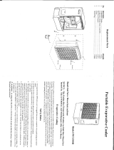
Cooler Installation
Install Pedestal and Casters
Unpack the unit and remove the media frame to access the pedestal and 4 cast-
ers. See the maintenance section for instructions on removing media frame.
CAUTION: Do not damage hose connecting pump to media frame. Cut
the cable ties holding pedestal to frame of unit and remove pedestal. Remove
the casters from the underside of the pedestal. To install the pedestal, turn the
unit on it’s side. Line up the bosses on the pedestal to the bosses on the base
of the unit (see fi g. 1). Use the four provided screws to attach the pedestal
to the base of unit. Press the stem casters into each corner hole of pedestal,
installing the 2 locking casters on the front and the 2 non-locking on the back
side.
Operation
Fill With Water
To fi ll this unit with water, open the water fi ll door and fi ll with a
pitcher or water hose (see fi g. 2). Do Not Overfi ll. CAUTION:
Take care when moving unit fi lled with water, spillage may
occur. Unlock casters when moving. Do not tip unit.
Water Level Indicator
On the front of the unit there is an access window to view the
level of the water (see fi g. 2). When the unit is full of water, the
level indicator will be at the top of the window and as the level
of the water is decreased in the unit, the indicator will lower.
Refer to the control panel in fi gure 3 for the following instructions.
Turning On Unit
Once the unit is plugged in, pressing the “Power” button will light up the backlight on the display and start
the unit in Fan-High mode. The pump will not start until the “Pump” button is pressed. The display will
remain backlit for 2 minutes after the last button on the control is pushed.
Pump / Cooler Operation
To operate this unit as an evaporative cooler, the unit must be fi lled with water and the pump powered on.
Press the “Pump” button to turn on the pump. The water drop indicator on the display will fl ash while the
pump is on. To operate the unit as a fan only, press “Pump” to turn off the pump.
Note: The pump will not run if the water level falls below a certain level. When the water level drops
below this level, an audible alarm will sound and the “Low Water” indicator on the display will fl ash on
and off. The audible alarm will stop after 60 seconds or when the “Pump” button is pushed. The indica-
tor will remain fl ashing until the unit is fi lled with water. You will need to restart the pump by pressing
“Pump” after the unit is refi lled with water.
Fan Operation
Pressing the “Speed” button on the control will cycle the fan
speed from High to Mid to Low. The speed setting will be
highlighted in the display.
Oscillate Mode
Pressing the “Oscillate” button will oscillate the vertical vanes
back and forth, distributing the air side to side. The “Oscillate”
indicator on the display will be displayed when on. Press the
button again to turn off.
Timer Mode
This unit is equipped with a timer. You may set the time interval for the unit to stay on. Pressing the
“Timer” button will set the time interval in 1/2 hour increments up to 8 hours. The display will fl ash while
setting the time and will display constantly once it is set. The display will count down the time remaining
in 1/2 hour increments. When the time interval is reached, the unit will turn off.
FAN PUMP
TIMER
OSCILLATE
LOW
MID
HIGH
COOL VENT
LOW WATER
hr
Oscillate
Timer
Power
Speed
Pump
Fig. 3
2
Water
Fill
Door
Water Level
Indicator
Fig. 2
Caster
Pedestal
Base
Fig. 1
Screw

Limited Warranty
This warranty is extended to the original purchaser of an evaporative cooler installed and used under nor-
mal conditions. It does not cover damages incurred through accident, neglect, or abuse by the owner. We
do not authorize any person or representative to assume for us any other or different liability in connection
with this product.
Terms And Conditions Of The Warranty
For One Year from date of purchase, we will replace any original component provided by Champion
Cooler which fails due to any defect in material or factory workmanship only.
Exclusions From The Warranty
We are not responsible for replacement of evaporative media. These are disposable components and
should be replaced periodically. We are not responsible for any incidental or consequential damage result-
ing from any malfunction.
We are not responsible for any damage received from the use of water softeners, chemicals, de-scale mate-
rial or plastic wrap.
We are not responsible for the cost of service calls to diagnose the cause of trouble, or labor charge to
repair and/or replace parts.
How To Obtain Service Under This Warranty
Contact the Dealer where you purchased the evaporative cooler. If for any reason you are not satisfi ed
with the response from the dealer, contact the Customer Service Department: Champion Cooler, 5800
Murray Street, Little Rock, Arkansas 72209. 1-800-643-8341. info@championcooler.com
This limited warranty applies to the original purchaser only.
Register your product online at www.championcooler.com/eac/onlineregistration-eac.htm
Maintenance
WARNING: Before doing any maintenance be sure unit is unplugged.
Drain Unit
To drain the unit, remove the media frame and remove the rubber drain stopper from the bottom of the unit
by pulling it out of the drain hole. The unit should be drained periodically to keep the water fresh. We
recommend draining the unit once a week. Drain the water from the unit when it will not be used for an
extended period.
Note: To remove the media frame, fi rst remove the two screws located at the top of the frame (see
fi g. 4). Tilt the frame back while pressing on the bottom of the frame where it says “Push” until it
snaps out, then lift out. The water distribution hose can be removed from the media frame to allow
complete separation of media frame from unit. Do not operate unit with media frame removed.
Clean/Replace Evaporative Media
The evaporative media should be cleaned twice a season or when
needed. To clean the media, rinse with clean water. Light scrub-
bing might be necessary. Be careful not to damage media. After
2 years, or when it becomes clogged, the media will need to be
replaced. To remove the media, fi rst remove the keeper disks from
the keeper stems (see fi g. 4). Remove the keeper stems from the
media and remove the media.
When replacing the evaporative media, install it so that the steeper
fl ute angle of the media is sloping down towards the media frame
(see fi g. 4). Push the keeper stems through the media from the
back of the media frame and press the keeper disks onto the stems
to secure the media in place.
3
Keeper
Disk
Keeper
Stem
Fig. 4
45°
15°
Screw

Trouble Shooting
Problem:
Cooler does not pump
water
Fan does not operate
Cause/Remedy:
• Water level is low. Fill with water and make sure Pump is activated.
• Pump may be defective. Replace pump.
• Check that unit is plugged into a 120V power receptacle.
• Check the fuse or breaker.
• If connected to a GFCI outlet, check if it is tripped.
Replacement Parts
No. Description CP70
1 Evaporative Media..................................................................................110132-3
2 Evaporative Media Frame Assembly......................................................110874-1
3 Water Tray ..............................................................................................110874-3
4 Water Distributor Nozzle ........................................................................110874-4
5 Keepers (Set of 4) ...................................................................................110871
6 Pump .......................................................................................................110439-1
7 Drain Plug ...............................................................................................110698
8 Float Assembly .......................................................................................110873
9 Swivel Casters - Non-Locking ...............................................................110822-6
10 Swivel Casters - Locking........................................................................110822-7
11 Pedestal ...................................................................................................110874-2
12 Water Distributor Tubing ........................................................................110734-1
13 M4 x 12mm Pan Head S.S. Screws (Qty 2) ...........................................111130
14 M4 x 12mm Truss Head S.S. Screws (Qty 4) ........................................111131
4
8
5
5
1
9
10
9
10
6
7
11
2
12
4
3
13
14
/