
INSTALLATION
MANUAL
©
Scania CV AB 2016, Sweden
01:03 Issue 6.1 en-GB 1
Fuel system
Industrial engines
DC09, DC13, DC16
333 381

INSTALLATION
MANUAL
©
Scania CV AB 2016, Sweden
01:03 Issue 6.1 en-GB 2
Fuel tank...................................................................................................................3
Position................................................................................................................ 4
Fuel tank design .................................................................................................. 6
Main tank and buffer tank ................................................................................... 8
Fuel pipes..................................................................................................................9
Fuel filter ................................................................................................................ 11
XPI engines ....................................................................................................... 11
PDE engines ...................................................................................................... 13
Fuel heater for XPI engines.................................................................................. 14
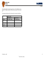
Feed pump flow rates ............................................................................................16
XPI engines ....................................................................................................... 16
PDE engines ...................................................................................................... 16
Flow and pressure .................................................................................................17
XPI engines ....................................................................................................... 17
PDE engines ...................................................................................................... 17
Risk of fire.............................................................................................................. 18
Fuel grade and power for PDE engines............................................................... 19

INSTALLATION
MANUAL
©
Scania CV AB 2016, Sweden
Fuel tank
01:03 Issue 6.1 en-GB 3
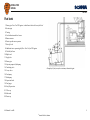
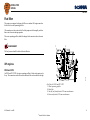
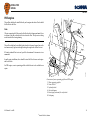
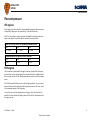
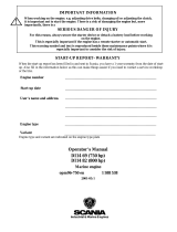
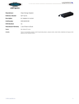
Fuel tank
1. Return pipe. Note: For XPI engines, it should enter below the lowest fuel level
2. Suction pipe
3. Venting
4. Level indication and level sensor
5. Bottom strainer
6. Drain tap with water separator
7. Shut-off cocks
8. Additional water separating fuel filter. Note: Not for XPI engines
9. Flexible fuel hoses
10. Buffer tank
11. Supply line
12. Return pipe
13. Injection pump with feed pump
14. Ventilating valve
15. 3-way valves
16. Feed pump
17. Hand pump
18. Inspection hatch
19. Fuel gauge
20. Overfill protection
21. Filler cap
22. Main tank
23. Drain tap
Example of a fuel system for a stationary industrial engine

INSTALLATION
MANUAL
©
Scania CV AB 2016, Sweden
Fuel tank
01:03 Issue 6.1 en-GB 4
Position
PDE and XPI engines
If the fuel tank is placed higher than the engine feed pump, a shut-off cock should be
installed in the fuel line to the feed pump. During stoppages, this cock should be
closed.
REQUIREMENT!
The highest fuel level in the tank is 3 m in relation to the feed pump.
REQUIREMENT!
Maximum permitted suction height is 2 m for PDE engines and 1 m for XPI engines.
The risk of air leaks in the suction pipe increases with increased vacuum. Suction
height is calculated from the bottom of the tank.
If the fuel tank is mounted lower than the maximum permitted suction height, or if a
large tank is required which cannot be mounted close to the engine, a buffer tank
must be installed at a suitable distance and height.
On stand-by generator sets, it is recommended that the tank always be positioned
above the level of the fuel manifold to prevent the engine's fuel system being drained
in the event of leakage.
If the tank(s) are built in, the space should be well ventilated.

INSTALLATION
MANUAL
©
Scania CV AB 2016, Sweden
Fuel tank
01:03 Issue 6.1 en-GB 5
XPI engines
If the tank is positioned so that suction height exceeds 1 m, a feed pump must be
mounted directly after the tank. The flow for the auxiliary feed pump must be mini-
mum 15% higher than the flows specified in the table found in the section Feed pump
flow rates.
To prevent fuel leakage during filter renewal, a shut-off cock must be installed on the
return pipe if the fuel tank is positioned higher than the engine.
To prevent unfiltered fuel from entering the engine during an inspection, a shut-off
cock must also be installed on the fuel pipe to the feed pump if fuel tank is placed
higher than the engine.
All XPI engines are equipped with a water-separating fuel filter. The water that is
separated follows with the return fuel. For this reason, all tanks must be fitted with a
drain tap for draining water.
The tank should normally be drained once a year, but this may vary depending on the
quality of the fuel.
If the customer requires extra water separation so that the water is not led back to the
fuel tank, a water separating fuel filter can be fitted on the return pipe.
IMPORTANT!
Fitting an extra water separating fuel filter in addition to the Scania prefilter is not
permitted on the fuel pipe to the engine.

INSTALLATION
MANUAL
©
Scania CV AB 2016, Sweden
Fuel tank
01:03 Issue 6.1 en-GB 6
Fuel tank design
The material for the fuel tank should be corrosion-resistant, such as stainless steel or
aluminium.
Note:
Some other materials, such as copper or hot dip galvanised sheet steel, are unsuitable
for use with diesel fuel.
The fuel tanks must be fully welded. When used in mobile installations, the fuel tanks
must be equipped with baffle plates.
Both fuel filling components and the fuel tank must be grounded to prevent sparking
from static electricity.
The fuel tank must have the following devices:
• A drain tap for emptying sludge and water that has sunk to the bottom.
• A connection with the outside air at the upper part of the tank to avoid a vacuum
in the tank. This can consist of a special bleed pipe or a ventilation hole in the fill-
er pipe cover. In dusty environments, this connection should be connected via a
filter to prevent dirt from entering the tank.
• Protection or filter to prevent contaminants entering during filling.
• Fuel pick-up unit with electronic overfill protection to prevent any diesel spillage.
• Main tanks must be fitted with inspection hatches so that they can be inspected
and cleaned inside.
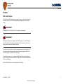
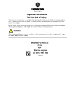
REQUIREMENT!
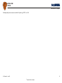
By law, the label "Ultra Low Sulfur Fuel Only" must be affixed at the filler cap on
all engines certified in accordance with Tier 4. The label is supplied with all indus-
trial engines from Scania.

INSTALLATION
MANUAL
©
Scania CV AB 2016, Sweden
Fuel tank
01:03 Issue 6.1 en-GB 7
New fuel tanks must be thoroughly cleaned and rinsed internally using clean fuel.
They must also be pressure tested to 0.3 bar.
Fuel tanks manufactured from materials which are not resistant to corrosion must be
treated externally with anti-corrosion paint.
Note that the tanks must not be painted internally nor be zinc-coated or galvanised.
Fuel tanks located outdoors should be painted in a bright, heat-reflecting colour, es-
pecially in hot climates with strong sunlight.
It is important that the fuel tanks are positioned in as cool a location as possible since
the return fuel is hot and therefore raises the temperature of the fuel in the tank.
Power correction due to increase in fuel temperature is displayed in the tables in the
section Fuel grade and engine power.
ULTRA LOW SULFUR
EU: 10ppm Sulfur Maximum
USA: 15ppm Sulfur Maximum
FUEL ONLY
338 656

INSTALLATION
MANUAL
©
Scania CV AB 2016, Sweden
Fuel tank
01:03 Issue 6.1 en-GB 8
Main tank and buffer tank
If the engine installation has a buffer tank and main tank, these should be designed
as follows:
• The main tank must have a sloped bottom or be on a slight incline (about 3-5°)
and have a tap at the lowest part for draining condensation.
• The pipe fittings must be connected or routed to approximately 50 mm from the
bottom and supplied with a bottom strainer. This applies to both the buffer tank
and the main tank.
• The lines to the buffer tank should be as short as possible and should be mounted
in such a way that they cannot be exposed to mechanical damage.
• Transfer of fuel from the main tank to the buffer tank should be achieved using
an electric pump connected so that it only pumps when the engine is running. This
is to prevent the risk of serious leakage when the engine is not running. The elec-
tric pump must have an overcapacity of approx. 15% over the feed pump flow.
This is to ensure that the quantity of return fuel is sufficient for lubrication and
cooling.
• There must be a return pipe from the buffer tank to the main tank so that any sur-
plus fuel runs back to the main tank.
• For PDE engines, the return pipe from the engine must be routed to the upper part
of the buffer tank.
• For XPI engines, the return pipe should enter below the lowest fuel level in the
main tank.
• The buffer tank must also be fitted with a drain tap for condensation.
• Tanks which are buried should have a drain pipe from the bottom to lead away
sludge and water.
See instructions in the Fuel tank design section for further details.

INSTALLATION
MANUAL
©
Scania CV AB 2016, Sweden
Fuel pipes
01:03 Issue 6.1 en-GB 9
Fuel pipes
The fuel lines should be routed so that the fuel cannot be heated by radiated heat from
the engine.
Engine power dependence on fuel temperature is indicated in the table under the sec-
tion Fuel grade and engine power. Maximum permitted fuel temperature in the inlet
pipe is 70°C.
The return line from the overflow valve must be routed to the fuel tank or to the buff-
er tank (if fitted).
Note:
The maximum permitted back pressure in the return line is 350 mbar.
The return line must not be connected to the suction line.
The return line and suction line must have the same diameter.
For PDE engines, the return line is normally connected to the upper part of the tank.
The return line should normally enter above the maximum fuel level.
IMPORTANT!
For XPI engines, the fuel return line should enter below the lowest fuel level in the
fuel tank.
The suction line in the fuel tank should be placed at least 50 mm from the bottom of
the fuel tank. This distance also applies to the suction strainer.
In multi-engine installations, the fuel system should be divided into at least two in-
dependent systems so that a fault in one of the fuel lines does not cause all engines
to stop.

INSTALLATION
MANUAL
©
Scania CV AB 2016, Sweden
Fuel pipes
01:03 Issue 6.1 en-GB 10
The fuel lines should not be made of copper as there is a risk of oxidation due to con-
densation. The sulphur content in the fuel can also have a negative effect on the cop-
per.
The minimum inside diameter of the fuel suction line is shown in the table below.
Fuel pipe length
Shorter than 3 m Longer than 3 m
Engine type Inner diameter (mm) Inner diameter (mm)
DC09 9 12
DC13 9 12
DC16 PDE 9 12
DC16 XPI 12 12

INSTALLATION
MANUAL
©
Scania CV AB 2016, Sweden
Fuel filter
01:03 Issue 6.1 en-GB 11
Fuel filter
The engines are equipped with paper fuel filters as standard. All engines must also
be fitted with a water separating prefilter.
All connections on the suction side of the feed pump must be thoroughly sealed so
that no air is drawn in during operation.
The water separating prefilter should be changed at the same intervals as the main
filter.
REQUIREMENT!
The fuel pressure should be checked after installation.
XPI engines
DC09 and DC13
On DC09 and DC13 XPI, the water separating prefilter is fitted on the engine on de-
livery. The connections on this filter and on the main filter are described on the right.
1
2
3
4
343 004
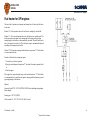
Fuel filter for DC09 and DC13 XPI
1. Water separating prefilter
2. Main filter
3. Inlet for fuel from fuel tank, Ø 12 mm outer diameter
4. Return to fuel tank, Ø 12 mm outer diameter

INSTALLATION
MANUAL
©
Scania CV AB 2016, Sweden
Fuel filter
01:03 Issue 6.1 en-GB 12
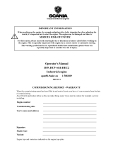
DC16
For DC16 XPI, the water separating prefilter is delivered separately. The connections
on this filter and on the engine-mounted main filter are described below.
Ite
m
A. Water separating prefilter Outer diameter
1 Fuel return from main filter 12 mm
2 Suction hose for water separation to main filter 6 mm
3 Out to feed pump 16 mm
4 In from fuel tank 16 mm
Ite
m
B. Engine-mounted main filter Outer diameter
1 Fuel return to prefilter 12 mm
2 Suction hose for water separation from prefilter 6 mm
3 In to feed pump 16 mm
4 Return to fuel tank 12 mm
AB
4
1
1
2
2
3
4
3
370 531
Fuel filter for DC16 XPI.

INSTALLATION
MANUAL
©
Scania CV AB 2016, Sweden
Fuel filter
01:03 Issue 6.1 en-GB 13
PDE engines
The prefilter should not be installed directly on the engine and a shut-off cock should
be fitted before the filter.
Note:
All water separating fuel filters must be fitted before the feed pump and must be low
in relation to the tank so that the fuel is forced into the filter. This prevents air being
sucked into the filter during draining.
The prefilter should not be installed higher than the feed pump, because that results
in an unnecessarily high suction height, making the engine more difficult to start.
If Scania's standard filter is not used, a prefilter of maximum 10 micrometres is rec-
ommended.
In multi-engine installations, there should be extra fuel filters between each engine
and the fuel tank.
For PDE engines, a water separating prefilter with fuel heater is also available as an
option.
1
3
4
5
6
2
353 447
Connection of water separating prefilter on PDE engine
1. Water separating prefilter
2. Union M16x1.5
3. In from fuel tank
4. Out to feed pump
5. Return pipe from main filter to fuel tank
6. Feed pump

INSTALLATION
MANUAL
©
Scania CV AB 2016, Sweden
Fuel heater for XPI engines
01:03 Issue 6.1 en-GB 14
Fuel heater for XPI engines
The switch has 3 positions (see diagram) and a lamp that is lit when the fuel heater
is activated:
Position "0": A fixed position where the fuel heater is completely switched off.
Position "1": A fixed switch position where the fuel heater is in standby mode. The
fuel heater requires the engine to be running and the alternator to be providing
enough charge to the batteries to be automatically activated. When the fuel heater is
active, the lamp in the switch is lit. The fuel heater output is automatically adjusted
according to the temperature of the fuel.
Position "2": This position is spring-loaded and returns to position "0". The fuel heat-
er is run on batteries only.
Proceed as follows before starting the engine:
1. Turn the key to the drive position.
2. Keep the switch depressed at position "2" for about 60 seconds to preheat the fu-
el.
3. Start the engine.
If the engine loses power during driving, set the switch to position "1". The fuel heat-
er is automatically activated when the engine is running and the alternator is provid-
ing enough charge to the batteries.
Material:
Connector 2-pin DTP: 1 907 302 (DTP06-2S-CE09) with shrinking tubing adapter
(Boot adapter).
Locking part: 1 507 728 (WP2S).
Cable terminal x 2: 1 507 723 (1062-12-1066) 2-4 mm
2
.

INSTALLATION
MANUAL
©
Scania CV AB 2016, Sweden
Fuel heater for XPI engines
01:03 Issue 6.1 en-GB 15
Shrinking tubing between connector and cable: Raychem type HTAT, size 24/6.

INSTALLATION
MANUAL
©
Scania CV AB 2016, Sweden
Feed pump flow rates
01:03 Issue 6.1 en-GB 16
Feed pump flow rates
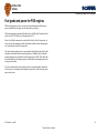
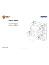
XPI engines
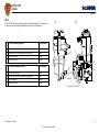
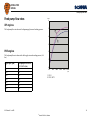
The feed pump flow rates shown in the diagram apply at normal working pressure.
PDE engines
The feed pump flow rates shown in the table apply at normal working pressure (4-6
bar).
Engine speed (rpm) Feed pump flow for DC09,
DC13, DC16 (l/hr)
500 93
1,200 223
1,500 276
1,800 330
2,000 369
2,100 387
2,200 405
L/min
rpm
0
90 500 1000 1500 1800 2300
1
2
3
4
5
6
1
2
313 359
1. DC16
2. DC09, DC13

INSTALLATION
MANUAL
©
Scania CV AB 2016, Sweden
Flow and pressure
01:03 Issue 6.1 en-GB 17
Flow and pressure
XPI engines
For all engine types, the external fuel system should be designed so that any vacuum
at the prefilter connection is not greater than 0.10 bar with clean filters.
For DC16, the prefilter is supplied separately and should be positioned at the same
height as the engine. The pressure must be measured before the prefilter.
PDE engines
The external fuel system should be designed so that any vacuum in the feed pump
suction line due to static suction height, flow resistance in fuel lines or additional fuel
filters is no greater than 0.20 bar. Measurement must be carried out at the feed pump
intake.
If the filter becomes blocked, pressure in the feed pump could rise. To prevent mal-
function, back pressure downstream of the feed pump must not exceed 10 bar, which
is the maximum capacity of the feed pump.
An overflow valve with an opening pressure of approx. 6 bar is fitted on the fuel
manifold. It ensures that the feed pump is always filled with fuel, which ensures that
the engine can start.
Return flow at full pressure in the fuel manifold and max. power
DC09 DC13 DC16
0.5-3.5 l/min 0.5-3.5 l/min 0.5-5 l/min
Maximum permitted back pressure in the return pipe
DC09 DC13 DC16
0.35 bar 0.35 bar 0.35 bar

INSTALLATION
MANUAL
©
Scania CV AB 2016, Sweden
Risk of fire
01:03 Issue 6.1 en-GB 18
Risk of fire
When working on the fuel system and handling diesel, observe the normal regula-
tions for handling flammable substances:
• Any source of ignition must be kept away from or be screened from the flamma-
ble material or area. Examples of circumstances that could cause ignition are
–welding
–smoking
– grinding with a grinder
– sparks from static discharge or electrical equipment.
• The ventilation in the engine compartment must be satisfactory for the evacuation
of fuel vapours.
• Be careful when filling the fuel tank with fuel. If the fuel tank is close to the en-
gine, the engine should be switched off and allowed to cool.
WARNING!
Heated diesel constitutes a risk of explosion!

INSTALLATION
MANUAL
©
Scania CV AB 2016, Sweden
Fuel grade and power for PDE engines
01:03 Issue 6.1 en-GB 19
Fuel grade and power for PDE engines
Different fuel properties such as viscosity, density and temperature influence the
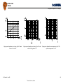
power available from the engine. See the charts on the next page.
The listed engine power assumes fuel with a density of 0.84 kg/dm
3
and specific cal-
orific value of 42,700 kJ/kg at a fuel temperature of 15°C.
Since it is difficult to measure the exact calorific value for the fuel in question, vis-
cosity, density and temperature can be used instead to obtain a corrected engine pow-
er as a percentage for each of the properties.
The read corrected engine powers as a percentage from the figures must first be add-
ed together to obtain the final corrected engine power. Multiply this with Scania's
specified engine power to obtain the corrected engine power in kW. Then add or sub-
tract from Scania's specified engine power to obtain the corrected engine power with-
in the given tolerances.
If you have measured the current engine power for a particular engine instead and
wish to convert it to normal power, change the sign in front of the corrected engine
power in the charts.

INSTALLATION
MANUAL
©
Scania CV AB 2016, Sweden
Fuel grade and power for PDE engines
01:03 Issue 6.1 en-GB 20
Engine power dependence on viscosity of fuel. Normal
value is 3 cSt at 40°C
Engine power dependence on density of fuel. Normal
value is 0.84 kg/dm³ at 15°C
Engine power dependence on temperature of fuel. The
reference temperature is 35°C
-
 1
1
-
 2
2
-
 3
3
-
 4
4
-
 5
5
-
 6
6
-
 7
7
-
 8
8
-
 9
9
-
 10
10
-
 11
11
-
 12
12
-
 13
13
-
 14
14
-
 15
15
-
 16
16
-
 17
17
-
 18
18
-
 19
19
-
 20
20


Scania DC16 Installation guide
- Type
- Installation guide
Ask a question and I''ll find the answer in the document
Finding information in a document is now easier with AI
Related papers
-
 Scania DI16 Installation guide
-
 Scania DI16 Installation guide
-
 Scania DC09 Installation guide
-
 Scania OC16 Installation guide
-
 Scania DI13 series User manual
-
 Scania DI14 69 User manual
-
 Scania OC16 Installation guide
-
 Scania DI16 XPI series User manual
-
 Scania DI9 User manual
-
 Scania DC09 Installation guide


Other documents
-
 Origin Storage ADP-XPI-EU Datasheet
-
Mackie DC16 Road Case Operating instructions
-
Kenwood Electronics CAW-SC1591 Datasheet
-
Raychem PI-kablar Installation guide
-
ClimateMaster CP, MH, MV, PDE, EH, EV Install Manual
-
Terex TA300 Original Operating Instructions
-
Thomson MEC 310#GENSET CONTROLLER OPTION J-CANBUS J1939 User manual
-
-
 WÄRTSILÄ WÄRTSILÄ 50DF User manual
-
Saab 99 1982 User manual

