Page is loading ...

INSTALLATION
MANUAL
©
Scania CV AB 2016, Sweden
02:03 Issue 5.0 en-GB 1
Fuel system
Marine engines
DI09, DI13, DI16
333 381

INSTALLATION
MANUAL
©
Scania CV AB 2016, Sweden
02:03 Issue 5.0 en-GB 2
Fuel tank...................................................................................................................3
Position................................................................................................................ 3
Fuel tank design .................................................................................................. 4
Main tank and buffer tank ................................................................................... 4
Fuel pipes..................................................................................................................5
Minimum inside diameter of fuel lines ............................................................... 5
Fuel filter ..................................................................................................................6
PDE and XPI engines.......................................................................................... 6
PDE engines ........................................................................................................ 8
XPI engines ......................................................................................................... 9
Fuel cooler ..............................................................................................................10
Feed pump flow rates ............................................................................................11
PDE engines ...................................................................................................... 11
XPI engines ....................................................................................................... 11
Flow and pressure .................................................................................................12
PDE engines ...................................................................................................... 12
XPI engines ....................................................................................................... 12
Risk of fire.............................................................................................................. 13
Fuel grade and power for PDE engines...............................................................14
Important data.......................................................................................................16

INSTALLATION
MANUAL
©
Scania CV AB 2016, Sweden
Fuel tank
02:03 Issue 5.0 en-GB 3
Fuel tank
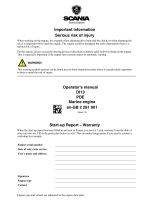
The illustration shows an example of a marine fuel tank installation.
Position
If the fuel tank is placed higher than the engine feed pump, a shut-off cock should be
installed in the fuel line to the feed pump. During downtime, this cock should be
closed. Maximum permitted fuel level in the fuel tank is 3.5 m in relation to the feed
pump.
The fuel tank must not be positioned so low that the vacuum in feed pump suction
pipe is greater than 0.3 bar. The risk of air leaks in the suction pipe increases with
increased vacuum. See also the section Flow and pressure
.
If the fuel tank is mounted so low that the maximum permissible vacuum is exceeded,
or if a large fuel tank is required which cannot be mounted close to the engine, a buff-
er tank must be installed at a suitable distance and height. A feed pump must be fitted
directly downstream of the tank. The flow for the auxiliary feed pump must be min-
imum 15% higher than the flows specified in the Feed pump flow rates
section.
If a reliable and quick starting response is required, the buffer tank should be posi-
tioned adjacent to the engine with the lowest fuel level at the same level as the feed
pump. If the fuel tank(s) are built in, the space should be well ventilated. The fuel
tank should normally be drained once a year, but this may vary depending on the
quality of the fuel.
4
5
6
7
8
9
10
11
1
2
3
338 166
Example of a fuel tank installation.
1. Bleed pipe.
2. Fuel filler pipe with filler cap.
3. Lead-through sleeve of fuel-resistant rubber.
4. Inspection hatch.
5. Baffle plate.
6. Fuel cocks.
7. Prefilter.
8. Drain tap for sludge and water.
9. Suction pipe with strainer.
10. Return pipe. Note: For XPI engines, it should enter below the lowest fuel level.
11. Ground connection.

INSTALLATION
MANUAL
©
Scania CV AB 2016, Sweden
Fuel tank
02:03 Issue 5.0 en-GB 4
Fuel tank design
The material for the fuel tank should be corrosion-resistant, such as stainless steel or
aluminium.
Note:
Some other materials, such as copper or hot dip galvanised sheet steel, are unsuitable
for use with diesel fuel.
The fuel tanks must be fully welded, and should have internal baffle plates to prevent
the fuel being thrown about in heavy seas. Both fuel filling components and the fuel
tank must be grounded to prevent sparking from static electricity. The fuel tank must
have the following devices:
• A drain tap for emptying sludge and water that has sunk to the bottom.
• A ventilation or bleed line from the upper part of the fuel tank to the outside of
the hull. It should be designed so that water cannot enter and so that fuel cannot
run out when the ship is leaning heavily.
• Protection or filter to prevent contaminants entering during filling.
• There must always be a fuel cock in the suction line and in the return line if its
outlet in the tank is higher than the outlet from the engine. The return line should
be routed to the upper part of the fuel tank.
• Main tanks must be fitted with inspection hatches so that they can be inspected
and cleaned inside.
New fuel tanks must be thoroughly cleaned and rinsed internally using clean fuel.
They must also be pressure tested to 0.3 bar.
Fuel tanks manufactured from materials which are not resistant to corrosion must be
treated externally with corrosion protection. The fuel tanks must not be painted in-
ternally nor be zinc-coated or galvanised.
It is important that the fuel tanks are positioned in as cool a location as possible since
the return fuel is hot and therefore raises the temperature of the fuel in the fuel tank.
Power correction due to the fuel temperature increase for PDE engines is displayed
in the tables in the Fuel grade and power for PDE engines
section.
Main tank and buffer tank
If the engine installation has a buffer tank and main tank, these should be designed
as follows:
• The main tank must have a sloped bottom or be on a slight incline (about 3-5°)
and have a tap at the lowest part for draining condensation.
• The pipe fittings must be connected or routed to approximately 50 mm from the
bottom and supplied with a bottom strainer. This applies to both the buffer tank
and the main tank.
• The lines to the buffer tank should be as short as possible and should be mounted
in such a way that they cannot be exposed to mechanical damage.
• Transfer of fuel from the main tank to the buffer tank should be achieved using
an electric pump connected so that it only pumps when the engine is running. This
is to prevent the risk of serious leakage when the engine is not running. The elec-
tric pump must have an excess capacity of 30-40% in relation to the engine fuel
consumption. This is to ensure that the quantity of return fuel is sufficient for lu-
brication and cooling.
• There must be a return pipe from the buffer tank to the main tank so that any sur-
plus fuel runs back to the main tank.
• For PDE engines, the return pipe from the engine must be routed to the upper part
of the buffer tank.
• For XPI engines, the return pipe should enter below the lowest fuel level in the
main tank.
• The buffer tank must also be fitted with a drain tap for condensation.
See instructions in the Fuel tank design
section for further details.

INSTALLATION
MANUAL
©
Scania CV AB 2016, Sweden
Fuel pipes
02:03 Issue 5.0 en-GB 5
Fuel pipes
The fuel lines should be routed so that the fuel cannot be heated by radiated heat from
the engine.
The dependency of engine power on fuel temperature can be read in the tables in the
Fuel grade and power for PDE engines
section. Maximum permitted fuel temperature
in the inlet pipe is 60°C.
The return line must be routed to the fuel tank or to the buffer tank (if fitted).
Note:
The return line must not be connected to the suction line.
For PDE engines, the return line is normally connected to the upper part of the tank.
The return line should normally enter above the maximum fuel level. For PDE en-
gines, the return pipe and suction pipe must have the same diameter.
Note:
For XPI engines, the fuel return line should enter below the lowest fuel level in the
fuel tank.
The suction line in the fuel tank should be placed at least 50 mm from the bottom of
the fuel tank. This distance also applies to the suction strainer.
In multi-engine installations, the fuel system should be divided into at least two in-
dependent systems so that a fault in one of the fuel lines does not cause all engines
to stop.
The fuel lines should not be made of copper as there is a risk of oxidation due to con-
densation. The sulphur content in the fuel can also have a negative effect on the cop-
per.
Minimum inside diameter of fuel lines
PDE engines
Type of fuel pipe Fuel pipe length
Shorter than 3 m, Longer than 3 m,
min. inner diam. (mm) min. inner diam. (mm)
Suction pipe 10 12
Return pipe 10 12
XPI engines
Type of fuel pipe Fuel pipe length
Shorter than 3 m, Longer than 3 m,
min. inner diam. (mm) min. inner diam. (mm)
Suction pipe 14 16
Return pipe 10 12

INSTALLATION
MANUAL
©
Scania CV AB 2016, Sweden
Fuel filter
02:03 Issue 5.0 en-GB 6
Fuel filter
PDE and XPI engines
The engines are equipped with an engine-mounted fuel filter. PDE engines also have
the option of commutative engine-mounted fuel filters which can be renewed during
operation.
All engines must also be fitted with a water separating prefilter. PDE engines require
one prefilter XPI engines require two prefilters, see next section. All connections on
the suction side of the feed pump must be thoroughly sealed so that no air is drawn
in during operation.
The water separating prefilter should be changed at the same intervals as the main
filter.
The prefilter should not be installed directly on the engine. If the fuel tank is posi-
tioned higher than the engine, a shut-off cock must be installed on the fuel pipe to the
feed pump, to prevent fuel running out into the hull during maintenance.
Information about how the single prefilter connector is connected is available in
03:01 Electrical system.
360
A=50
48,4
9,5
58,7 32,5
Ø107
12
2
1
35
12,7
373 818
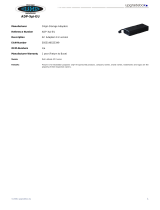
Single water separating prefilter.
1. Outlet, SAE 8 P ¾" 16 UNF 2B.
2. Intake, same dimensions as outlet.
A = Free space required for prefilter renewal.

INSTALLATION
MANUAL
©
Scania CV AB 2016, Sweden
Fuel filter
02:03 Issue 5.0 en-GB 7
It is also possible to install prefilters which are commutative. It is possible to renew
commutative fuel filters with the engine running by switching off one filter at a time.
These prefilters have a water separator and an indicator, which show when it is time
to renew the filters.
Note:
Always renew both filters at the same time.
145
124
98,5
248
385
B=254
98,5
83
85
124
SECTION A-A
476
A
A
14
1
2
373 817
Commutative water separating prefilter.
1. Intake, 7/8 14 UNF 2B straight thread with SAE J514 male JIC 37°.
2. Outlet, same dimensions as the intake.
B = Free space required for prefilter renewal.

INSTALLATION
MANUAL
©
Scania CV AB 2016, Sweden
Fuel filter
02:03 Issue 5.0 en-GB 8
PDE engines
PDE engines require one water separating prefilter.
Permitted water separating prefilters for PDE engines
• Single prefilter from Scania.
• Commutative prefilter from Scania.
• Prefilter from external supplier.
If a prefilter from an external supplier is installed, a filter of a maximum of
30 micrometres is recommended.
The prefilter should not be installed higher than the feed pump, because that results
in an unnecessarily high suction height, making the engine more difficult to start. In
multi-engine installations, there should be extra fuel filters between each engine and
the fuel tank.
Note:
All water separating prefilters must be fitted before the feed pump and must be low
in relation to the fuel tank so that the fuel is forced into the filter. This prevents air
being sucked into the filter during draining.
2
1
6
4
5
3
373 816
Fuel filter installation on PDE engines.
1. From fuel tank.
2. Water separating prefilter, maximum 30 micrometres.
3. Feed pump with hand pump.
4. Main fuel filter.
5. To injector.
6. Engine-mounted components.

INSTALLATION
MANUAL
©
Scania CV AB 2016, Sweden
Fuel filter
02:03 Issue 5.0 en-GB 9
XPI engines
XPI engines require two water separating prefilters.
First filtering stage (pos. 2 in illustration), permitted water separating prefilter
• Single prefilter from Scania.
• Commutative prefilter from Scania.
• Prefilter from external supplier.
If a prefilter from an external supplier is installed in the first filtering stage, a prefilter
of 20-30 micrometres is recommended.
Second filtering stage (pos. 3 in illustration), permitted water separating prefil-
ter
• Only the accompanying double prefilter from Scania may be used.
Note:
If no prefilter is installed in the first filtering stage, the renewal interval for the Scania
double prefilter in the second filtering stage reduces considerably.
1
2
3
8
6
4
5
7
373 049
Fuel filter installation on XPI engines.
1. From fuel tank.
2. Water separating prefilter, 20-30 micrometres.
3. Double water separating prefilter from Scania.
4. Hand pump.
5. Feed pump.
6. Main fuel filter.
7. To high pressure pump.
8. Engine-mounted components.

INSTALLATION
MANUAL
©
Scania CV AB 2016, Sweden
Fuel cooler
02:03 Issue 5.0 en-GB 10
Fuel cooler
If there is a risk of the fuel being heated up due to the routing of fuel lines, a fuel cool-
er can be connected in the sea water circuit upstream of the sea water pump.
338 167
Seawater-cooled fuel cooler.

INSTALLATION
MANUAL
©
Scania CV AB 2016, Sweden
Feed pump flow rates
02:03 Issue 5.0 en-GB 11
Feed pump flow rates
PDE engines
The feed pump flow rates shown in the table apply at normal working pressure (4-6
bar).
XPI engines
The feed pump flow rates shown in the diagram apply at normal working pressure.
Engine speed (rpm) DI09, DI13 (l/hour) DI16 (l/hour)
500 91 135
1,200 220 340
1,500 271 380
1,800 325 400
1,900 362 400
2,100 380 400
2,200 398 400
2,300 417 400
L/min
r
pm
0
90
500
1000 1500 1800 2300
1
2
3
4
5
6
357 878
Feed pump flows for DI16 XPI.

INSTALLATION
MANUAL
©
Scania CV AB 2016, Sweden
Flow and pressure
02:03 Issue 5.0 en-GB 12
Flow and pressure
The external fuel system should be designed so that any vacuum in the feed pump
suction line due to static suction height, flow resistance in fuel lines or additional fuel
filters is no greater than 0.3 bar. Measurement must be carried out at the feed pump
intake. Refer to 02:08 Measuring instructions for installation inspection.
PDE engines
If the filter becomes blocked, pressure in the feed pump could rise. To prevent mal-
function, back pressure downstream of the feed pump must not exceed 10 bar, which
is the maximum capacity of the feed pump.
An overflow valve with an opening pressure of approx. 6 bar is fitted on the fuel
manifold. It ensures that the feed pump is always filled with fuel, which ensures that
the engine can start.
XPI engines
The prefilter should be positioned at the same height as the engine.
Return flow at full pressure in the fuel manifold and max. power
0.5-5 l/min
Maximum permitted back pressure in the return pipe
0.35 bar

INSTALLATION
MANUAL
©
Scania CV AB 2016, Sweden
Risk of fire
02:03 Issue 5.0 en-GB 13
Risk of fire
When working on the fuel system and handling diesel, observe the normal regula-
tions for handling flammable substances:
• Any source of ignition must be kept away from or be screened from the flamma-
ble material or area. Examples of circumstances that could cause ignition are
–welding
–smoking
– grinding with grinding machines
– sparks from static discharge or electrical equipment.
• The ventilation in the engine compartment must be satisfactory for the evacuation
of fuel vapours.
• Be careful when filling the fuel tank with fuel. If the fuel tank is close to the en-
gine, the engine should be switched off and allowed to cool.
WARNING!
Heated diesel constitutes a risk of explosion!

INSTALLATION
MANUAL
©
Scania CV AB 2016, Sweden
Fuel grade and power for PDE engines
02:03 Issue 5.0 en-GB 14
Fuel grade and power for PDE engines
Different fuel properties such as viscosity, density and temperature influence the
power available from the engine. See the charts on the next page.
The listed engine power assumes fuel with a density of 0.84 kg/dm
3
and specific cal-
orific value of 42,700 kJ/kg at a fuel temperature of 15°C.
Since it is difficult to measure the exact calorific value for the fuel in question, vis-
cosity, density and temperature can be used instead to obtain a corrected engine pow-
er as a percentage for each of the properties.
The read corrected engine powers as a percentage from the figures must first be add-
ed together to obtain the final corrected engine power. Multiply this with Scania's
specified engine power to obtain the corrected engine power in kW. Then add or sub-
tract from Scania's specified engine power to obtain the corrected engine power with-
in the given tolerances.
If you have measured the current engine power for a particular engine instead and
wish to convert it to normal power, change the sign in front of the corrected engine
power in the charts.

INSTALLATION
MANUAL
©
Scania CV AB 2016, Sweden
Fuel grade and power for PDE engines
02:03 Issue 5.0 en-GB 15
Engine power dependence on viscosity of fuel. Normal
value is 3 cSt at 40°C.
Engine power dependence on density of fuel. Normal
value is 0.84 kg/dm³ at 15°C.
Engine power dependence on the fuel temperature. The
reference temperature is 35°C.
.

INSTALLATION
MANUAL
©
Scania CV AB 2016, Sweden
Important data
02:03 Issue 5.0 en-GB 16
Important data
Maximum vacuum in the feed pump suction line using a cleaned or new filter 0.3 bar
Max. backpressure downstream of the feed pump when the filter is blocked 10 bar
Max. fuel temperature upstream of the feed pump 60°C
Max. fuel level above feed pump 3.5 m
Engine power dependence on viscosity of fuel See the chart on the previous page
Engine power dependence on density of fuel See the chart on the previous page
Engine output dependence on fuel temperature See the chart on the previous page
Normal fuel pressure 4-6 bar
/