Page is loading ...

INSTALLATION
MANUAL
©
Scania CV AB 2016, Sweden
01:05 Issue 8.0 en-GB 1
Cooling system
Industrial engines
DC09, DC13, DC16
333 379

INSTALLATION
MANUAL
©
Scania CV AB 2016, Sweden
01:05 Issue 8.0 en-GB 2
Design and dimensioning ........................................................................................3
Expansion tank ........................................................................................................4
Pressure drop and coolant flow..............................................................................5
Radiators and radiator fans ................................................................................... 7
Installation of radiator and radiator fan............................................................... 7
Radiator fans ....................................................................................................... 8
Engine-mounted radiators 1.1 m2 and 1.3 m2 .................................................... 9
Cooling capacity................................................................................................ 10
Thermostat .............................................................................................................11
Connecting a cab heater........................................................................................12
Transmission oil cooling .......................................................................................13
Connecting a transmission oil cooler ................................................................ 13
Immersion heater ..................................................................................................15
Multi-engine installation with common cooling system.....................................16
Filling coolant ........................................................................................................18
Installation instructions for the cooling system .................................................. 20
Protective casing for the 1.1 m² cooling package ............................................. 20
Protective casing for the 1.3 m² cooling package ............................................. 21
Pipes and hoses.................................................................................................. 22

INSTALLATION
MANUAL
©
Scania CV AB 2016, Sweden
Design and dimensioning
01:05 Issue 8.0 en-GB 3
Design and dimensioning
The design of the cooling system is an important part of the engine installation. It
should therefore be planned carefully when ordering the engine. The cooling require-
ment is dependent on the engine power, engine installation layout and the surround-
ing environment.
If the engine is supplied from Scania without a cooling system, the radiator must have
sufficient capacity for the applicable operating conditions.
Scania accepts no responsibility for the function of cooling systems which are calcu-
lated and installed other than according to Scania's instructions.
Note:
It is the responsibility of the fitter to ensure that the cooling system is dimensioned
and tested so that it works in the applicable operating conditions.
The Data Handbook contains cooling system recommendations for all engines. If the
engine installation and the operating conditions deviate from these recommenda-
tions, the cooling system must be designed for the relevant engine installation.
When dimensioning a cooling system, the following data must be available.
• Heat output that the cooling system must conduct away from the engine. Refer to
01:06 Technical data.
• Fan capacity. Information on the fan capacity of Scania fans is in the Data Hand-
book.
• Pump capacity: Coolant flow as a function of engine speed versus pressure drop.
See Pressure drop and coolant flow
.
• The maximum ambient temperature in which the engine is to operate. Scania rec-
ommends dimensioning the cooling system with a margin of at least 5°C to com-
pensate for any clogging of the radiator.
• Alarm limits for the coolant temperature.
The following factors must also be taken into consideration:
• With a pusher fan the cooling air is warmed up when it passes the engine. Heating
is approximately 10°C with Scania standard fans. Other components which gen-
erate heat also contribute to this heating.
• Additional heat from other components connected to the cooling system.
IMPORTANT!
Dimension the cooling system for the entire engine speed range, not just for maxi-
mum engine speed.

INSTALLATION
MANUAL
©
Scania CV AB 2016, Sweden
Expansion tank
01:05 Issue 8.0 en-GB 4
Expansion tank
The design of the cooling system must always allow the coolant to expand in an ex-
pansion tank. The expansion tank must be positioned slightly higher than the highest
part in the rest of the cooling system. The volume for expansion (proportion of air)
in the expansion tank should be at least 3% and the reserve volume (proportion of
coolant) should be at least 5% of the total coolant volume.
The expansion tank should be connected to the suction side of the coolant pump with
a static line pipe to reduce the risk of steam build-up and cavitation in the pump. This
connection should have as even a rise as possible to avoid pockets of air.
The outer diameter of the pipe or the inner diameter of the hose should be a minimum
of 25 mm for DC09 and DC13 and a minimum of 32 mm for DC16.
There must always be a bleed pipe between the upper part of the radiator and the ex-
pansion tank to prevent air from entering the cooling system. The inner diameter of
the bleed pipe must not be greater than 8 mm to avoid the flow becoming too great.
There must be a bleed pipe from the vent port on the cylinder heads to the expansion
tank.
If an external heating system is to be connected to the cooling system, Scania recom-
mends positioning the expansion tank higher than the external heating system.
IMPORTANT!
The expansion tank must not be positioned higher than 8.5 m above the coolant pump
intake. This height corresponds to a static pressure of 0.85 bar, the highest pressure
permissible on the suction side of the pump to avoid leakage.

INSTALLATION
MANUAL
©
Scania CV AB 2016, Sweden
Pressure drop and coolant flow
01:05 Issue 8.0 en-GB 5
Pressure drop and coolant flow
The coolant pipes and hose connections between engine and radiator must be dimen-
sioned in a manner that prevents reduction of cooling capacity.
An adequate quantity of coolant and cooling air must be able to pass through the
pipes and radiator. Connecting components or restriction valves in the system reduc-
es the amount of coolant passing through the radiator and thereby reduces the cooling
capacity. At the same time, this increases the pressure in thermostat housing, hoses
and cooler.
The diameter of coolant lines should be 57 mm. This measurement refers to the outer
diameter for pipes and the inner diameter for hoses.
The coolant lines should be made of pipe, which is bent and jointed with short
straight hoses. Ribbed hoses can hinder flow.
Maximum permissible pressure drop and minimum coolant flow are depicted in the
diagrams on this and the next page.
If in doubt, check that the pressure drop across the external system does not exceed
permissible values.
The pressure drop is determined by measuring the difference in pressure between the
thermostat housing and the intake to the coolant pump with the thermostats blocked
in the open position (8 mm opening) and with no pressure cap. See the Thermostat
-
section.
361 898
The diagram applies to DC09/DC13 with EGR system (Stage IV/Tier 4f and DC09/
DC13 071A).
361 897
The diagram applies to DC09/DC13 without EGR system.

INSTALLATION
MANUAL
©
Scania CV AB 2016, Sweden
Pressure drop and coolant flow
01:05 Issue 8.0 en-GB 6
1200 rpm
1500 rpm
1800 rpm
2000 rpm
2200 rpm
MAXIMUM
RESTRICTION
0
0,25
0,5
0,75
1
1,25
1,5
1,75
2
Dp
bar
250 300 350 400 450 500 550 600 650
L/min
331 035
The diagram applies to DC16.

INSTALLATION
MANUAL
©
Scania CV AB 2016, Sweden
Radiators and radiator fans
01:05 Issue 8.0 en-GB 7
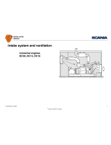
Radiators and radiator fans
Installation of radiator and radiator fan
In order to fully utilise the capacity of the radiator and radiator fan, a fan cover with
fan ring should be placed between the radiator and the radiator fan. In addition there
must be a sufficient distance between the radiator and radiator fan, as well as between
the radiator fan and fan ring, in order for cooling to work effectively.
The optimum distance between radiator fan and radiator is 0.3 x fan diameter. This
is often not possible due to lack of space. 130-150 mm is acceptable as a minimum
distance.
The distance between the fan blade and fan ring should preferably not exceed 6 mm
as shown in the figure.
For engines with flexible engine suspension, engine movements can cause the fan to
come into contact with the fan ring if it is fitted on the radiator. The alternative is to
fit the fan ring on the engine and seal the ring and fan cover with an elastic spacer.
It is important for the air which has passed through the radiator and has been heated
not to be recirculated so that it passes through the radiator again. It may therefore be
necessary to place a shield around the radiator to prevent recirculation.
317 277
Installation of fan ring and fan cover.
A = Distance between fan and radiator. The distance should preferably be 0.3 x fan
diameter, but 130-150 mm is acceptable as a minimum distance.
1. Radiator.
2. Fan cover.
3. Elastic sealing ring.
4. Fan ring.
5. Fan.

INSTALLATION
MANUAL
©
Scania CV AB 2016, Sweden
Radiators and radiator fans
01:05 Issue 8.0 en-GB 8
Radiator fans
The engines are available with 2 types of radiator fan – a pusher fan or puller fan.
The significant difference between the two systems is that a puller fan provides a
more even distribution of the air flow through the radiator. See the illustrations.
With a pusher fan, the cooling capacity is also reduced as the cooling air is warmed
when it passes the engine, exhaust pipe and driven unit. A pusher fan also results in
a greater pressure drop across the radiator since the distribution over the surface of
the radiator is not so good.
This means that a particular size of radiator requires a larger volume of air with a
pusher fan to achieve the same cooling capacity.
The fan ring must be correctly located and designed for the fan to achieve maximum
air flow and to ensure that distribution across the radiator is as efficient as possible.
See Installation of radiator and radiator fan
.
In order to optimise the cooling capacity, first check that heated air is not being re-
circulated. If it is, a suitable shield must be fitted. The second measure is to increase
the size of the radiator.
It is possible to optimise the fan speed or fan diameter to increase capacity. If the size
of the fan or the fan speed is changed the power requirement and noise level of the
fan increase. Information about permissible combinations can be found in the Data
Handbook.
A pusher fan can help to combat heating of the engine compartment by dissipating
heat radiated by the engine, exhaust pipe and driven unit.
340 450
Air flow through radiator with pusher fan.
340 451
Air flow through radiator with puller fan.

INSTALLATION
MANUAL
©
Scania CV AB 2016, Sweden
Radiators and radiator fans
01:05 Issue 8.0 en-GB 9
Engine-mounted radiators 1.1 m
2
and 1.3 m
2
The engine-mounted 1.1 m
2
radiator has been specially developed for operation in
extremely dusty environments such as stone crushing plants.
The 1.1 m
2
radiator is intended for DC09 and DC13 engines, with an output of be-
tween 202 kW and 405 W for engines without EGR systems, and between 202 kW
and 331 kW for engines with EGR systems.
The engine-mounted 1.3 m
2
radiator is intended for operation in normal environ-
ments.
The 1.3 m
2
radiator is intended for DC13 single-speed engines with a power output
of between 325 kW and 487 kW.
The engine-mounted radiators are installed on the engine using reinforced brackets
that are included in the cooling package. Air and coolant connections are prein-
stalled.
REQUIREMENT!
An engine-mounted radiator must not be allowed to hang freely. A beam should be
placed under the radiator during installation.
338 659
1010
710
DC09: 965,5
DC13: 1129,5
726
400
230
466 949
Engine-mounted radiator 1.1 m² for DC09 and DC13.
338 658
1129,5
265
899
1160
680
496
550 1175
230
48
Engine-mounted radiator 1.3 m² for DC13 (single-speed engines).

INSTALLATION
MANUAL
©
Scania CV AB 2016, Sweden
Radiators and radiator fans
01:05 Issue 8.0 en-GB 10
Cooling capacity
In order to determine the safety margin, the actual coolant temperature (t) must be
measured at the outlet from the thermostat housing when the engine is running at full
power with fully open thermostats. The thermostats should be blocked into the open
position in accordance with the instructions in following section.
Then calculate T max., the highest ambient temperature the engine can work in at
maximum load, using the following formula:
Determine the safety margin by comparing the resulting "T max" with the ambient
temperature for which the engine installation is designed. The margin should always
be greater than 5°C to compensate for radiator clogging.
T max. = L - t + T
where
L = Alarm limit for coolant temperature
T = Ambient temperature during testing
t = Actual coolant temperature at full power.
T max. = Maximum ambient temperature which the engine can work in without an
alarm for high engine temperature.

INSTALLATION
MANUAL
©
Scania CV AB 2016, Sweden
Thermostat
01:05 Issue 8.0 en-GB 11
Thermostat
The engines are equipped with a dual thermostat to reduce the risk of pulsation with
large amounts of coolant. The opening temperature for the thermostat that regulates
bypass is 80°C while the temperature for the other thermostat is 87°C. The operating
range of the thermostat, i.e. the difference between a closed and fully open thermo-
stat, is 15°C.
338 569
Thermostat.

INSTALLATION
MANUAL
©
Scania CV AB 2016, Sweden
Connecting a cab heater
01:05 Issue 8.0 en-GB 12
Connecting a cab heater
An external heating system such as a cab heater can be connected to the engine cool-
ant circuit as shown in the illustrations.
A cab heater must be equipped with a drain tap at the lowest point and venting at the
highest point. Scania recommends positioning the expansion tank in the cooling sys-
tem higher than an external heating system.
1. Connecting the intake line.
2. Connecting the return line.
1
2
1
338 660
DC09, DC13.
1. M18x1.5 or Ø 16 mm hose.
2. M22x1.5 or Ø 16 mm hose.
2
1
334 280
DC16.
Both the connections: M18x1.5 or Ø 16 mm hose

INSTALLATION
MANUAL
©
Scania CV AB 2016, Sweden
Transmission oil cooling
01:05 Issue 8.0 en-GB 13
Transmission oil cooling
If it is necessary to cool the transmission oil using the engine cooling system, the
cooling system must be designed to ensure sufficient capacity.
It is sometimes necessary to route the engine bypass pipe through the external oil
cooler.
The heat output to be conducted away from the transmission can be quite large and
must therefore be taken into account when designing the engine cooling system.
The installation should be constructed with coolant connection lines which are as
short as possible. The connection pipes should be dimensioned so that the pressure
drop is kept to a minimum, i.e. sufficient diameter and few sharp bends.
Connecting a transmission oil cooler
Oil coolers for the driven unit or transmission can be connected to the engine cooling
system in either of two ways:
• The oil cooler is connected between the engine's rear coolant pipe and an external
thermostat. This is recommended when the cooling requirement for the oil cooler
is as great or greater than the engine cooling requirement. The retarder oil cooler
is an example of this.
• The oil cooler is connected between the engine radiator and the suction side of the
coolant pump. There is then no circulation through the oil cooler before the ther-
mostat has opened, however, by installing an external thermostat and connecting
the by-pass pipe upstream of the oil cooler this can be avoided.
This system is not a primary recommendation, but can be employed when the
cooling requirement for the driven unit is not so great and corresponds to actual
engine output. Hydraulic oil coolers and transmission oil coolers are examples of
this.
DC09 and DC13
The figure shows 2 different options for connecting an oil cooler on DC09 and DC13.
7
4
5
6
1
2
3
340 453
1. Large retarder type oil cooler (recommended).
2. Outlet from engine.
3. Outlet to radiator.
4. Bypass line.
5. From radiator.
6. Small oil cooler.
7. Intake to engine.

INSTALLATION
MANUAL
©
Scania CV AB 2016, Sweden
Transmission oil cooling
01:05 Issue 8.0 en-GB 14
DC16
On the DC16 the oil cooler must be connected between the engine's rear coolant pipe
and the engine-mounted external thermostat as shown in the figure. This is the only
connection option which ensures a 100% coolant flow irrespective of how much the
thermostat is open.
Note:
The engine must be ordered from the factory with an external thermostat.
1
4
2
3
332 920
1. Outlet to radiator.
2. Intake from oil cooler.
3. Intake from radiator.
4. Outlet to oil cooler.

INSTALLATION
MANUAL
©
Scania CV AB 2016, Sweden
Immersion heater
01:05 Issue 8.0 en-GB 15
Immersion heater
If required, the engines can be supplied with an electric immersion heater. The im-
mersion heater can be selected with or without integrated thermostat. The thermostat
is set to a thoroughly tested temperature to ensure sufficient self-circulation. It also
prevents the temperature from becoming so high that oil film on e.g. the piston and
cylinder liner evaporates or dries.
For DC09 and DC13 both immersion heaters have a power output of 1,500 W and
are available for either 115 V or 230 V electrical power networks.
For DC16, immersion heaters are available with a thermostat with 2 power levels:
500 or 1,500 W. Choice of power depends primarily on how cold it can be around the
engine. The available power supply system can also be a key factor when selecting
power. Immersion heaters are available for either 115 V or 230 V power supply sys-
tems.
1 2 3 4
335 054
Immersion heater.
1. Without thermostat for DC09 and DC13.
2. With thermostat for DC09 and DC13.
3. Without thermostat for DC16.
4. With thermostat for DC16.

INSTALLATION
MANUAL
©
Scania CV AB 2016, Sweden
Multi-engine installation with common cooling system
01:05 Issue 8.0 en-GB 16
Multi-engine installation with common
cooling system
In multi-engine installations, the engines can be connected to a common external
cooling system following the outline diagram on the next page. A system like this
must be dimensioned and planned as follows:
• The capacity of the radiator should be well matched to the number of engines in
the engine installation and the overall coolant volume of the system. It is possible
to use a heat exchanger instead of radiators. This is then connected to an existing
cooling/heating installation in the building.
• The expansion tank should be dimensioned for an expansion volume of about 3%
and a reserve volume of about 5% of the total coolant volume. The reserve vol-
ume should always be at least 10 litres.
• There must be venting at the highest point in the pipe directly downstream of the
thermostat housing and on the venting manifold on the cylinder heads.
• There must also be a bleed pipe to the radiator inlet pipe. This must be connected
to the pipe at the highest point upstream of the radiator. A static line pipe should
be routed from the expansion tank to the suction side of the coolant pump. The
outer diameter of the pipe should be a minimum of 25 mm for DC09 and DC13
and a minimum of 32 mm for DC16.
• All bleed pipes should be connected to the expansion tank below the coolant level.
• The expansion tank must not be placed higher than 8.5 m above the engine cool-
ant pumps to avoid the pressure in their seals becoming too great.
• An extra circulation pump should be installed in the system if there is a risk of a
vacuum greater than 0.1 bar forming on the suction side of the coolant pumps.
• Circulation pump capacity should be equal to the maximum total flow when all
engines are running.
• Systems with an extra circulation pump should have an extra external bypass pipe
with a check valve (broken line in diagram) to reduce the coolant flow through an
engine which is not operating.
M1
12 3
4
6
7
8
9
10
11
5
M2
335 014
Outline diagram of cooling system in multi-engine installations.
1. Bleed pipe to expansion tank.
2. Expansion tank.
3. Bleed pipe from radiator.
4. Static line pipe.
5. Radiator or heat exchanger.
6. Extra circulation pump. Only on long lines with a large pressure drop.
7. Flexible hose.
8. Shut-off valve.
9. Engine coolant pump.
10. External pipe with check valve. Only for systems with an auxiliary circulation
pump.
11. Check valve in the engine intake. Only for systems without an auxiliary circula-
tion pump.

INSTALLATION
MANUAL
©
Scania CV AB 2016, Sweden
Multi-engine installation with common cooling system
01:05 Issue 8.0 en-GB 17
• Systems without an extra circulation pump should have check valves in the inlet
pipes to the engines to prevent circulation in a stationary engine.
• The connections to the engine may be flexible hoses. However, flexible hoses
should be used as little as possible as they can cause temperature oscillation.
• There should be shut-off valves as shown in the outline diagram to facilitate main-
tenance on the system.

INSTALLATION
MANUAL
©
Scania CV AB 2016, Sweden
Filling coolant
01:05 Issue 8.0 en-GB 18
Filling coolant
The fitter must ensure it is possible to top up coolant.
IMPORTANT!
It is not permissible to fill large amounts of coolant via the expansion tank. Filling
via the expansion tank leads to air pockets in the cooling system, which can damage
the coolant pump shaft seal, among other things.
Never fill a large amount of cold coolant in a hot engine. There is great risk of cracks
forming in the cylinder block and cylinder heads.
When the cooling system has been drained: Use coolant trolley 588 540, coolant
pump 2 443 679 or other suitable equipment, to fill with coolant through the drain
valve on the cylinder block.
Start the engine when the cooling system has been filled. Allow the engine to run for
a while. Then check the coolant level and top up with coolant via the expansion tank
as necessary.
337 371
Coolant trolley 588 540.
360 625
Coolant pump 2 443 679.

INSTALLATION
MANUAL
©
Scania CV AB 2016, Sweden
Filling coolant
01:05 Issue 8.0 en-GB 19
The illustrations show the location of the drain valves.
340 455
Drain valve on DC09 and DC13.
340 454
Drain valve on DC16.

INSTALLATION
MANUAL
©
Scania CV AB 2016, Sweden
Installation instructions for the cooling system
01:05 Issue 8.0 en-GB 20
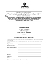
Installation instructions for the cooling
system
Protective casing for the 1.1 m² cooling package
Item Part No. Note Qty Designation
1 2 185 779 1 Protection mesh
812 515 M8x16 6 Flange screw
812 502 M6x16 6 Flange screw
2 2 074 871 1 Protection mesh
3 2 067 705 1 Protection mesh
812 502 M6x16 4 Flange screw
4 2 074 589 1 Protection mesh
812 515 M8x16 4 Flange screw
5 2 074 458 1 Protection mesh
812 502 M6x16 4 Flange screw
6 2 424 340 Without alternator 1 Protection mesh
812 515 M8x16 2 Flange screw
7 2 074 870 1 Protection mesh
8a 2 074 582 2 alternators 1 Protection mesh
812 502 M6x16 3 Flange screw
8b 2 074 583 Alternator and AC
compressor
1 Protection mesh
812 502 M6x16 4 Flange screw
8c 2 074 584 1 alternator 1 Protection mesh
812 502 M6x16 4 Flange screw
1
2
3
4
5
7
8b
8a
8c
6
362 439
/