Page is loading ...

POINT I/O and ArmorPOINT I/O 2 Port
EtherNet/IP Adapters
Catalog Numbers 1734-AENTR, 1738-AENTR
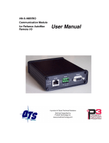
User Manual

Important User Information
Solid state equipment has operational characteristics differing from those of electromechanical equipment. Safety Guidelines for the Application,
Installation and Maintenance of Solid State Controls (publication SGI-1.1
available from your local Rockwell Automation sales office or online at
http://literature.rockwellautomation.com
) describes some important differences between solid state equipment and hard-wired electromechanical
devices. Because of this difference, and also because of the wide variety of uses for solid state equipment, all persons responsible for applying this
equipment must satisfy themselves that each intended application of this equipment is acceptable.
In no event will Rockwell Automation, Inc. be responsible or liable for indirect or consequential damages resulting from the use or application of this
equipment.
The examples and diagrams in this manual are included solely for illustrative purposes. Because of the many variables and requirements associated
with any particular installation, Rockwell Automation, Inc. cannot assume responsibility or liability for actual use based on the examples and
diagrams.
No patent liability is assumed by Rockwell Automation, Inc. with respect to use of information, circuits, equipment, or software described in this
manual.
Reproduction of the contents of this manual, in whole or in part, without written permission of Rockwell Automation, Inc., is prohibited.
Throughout this manual, when necessary, we use notes to make you aware of safety considerations
.
Allen-Bradley, Rockwell Automation, POINT I/O, ArmorPOINT I/O, RSLogix, RSLinx, RSLogix 5000, and TechConnect are trademarks of Rockwell Automation, Inc.
Trademarks not belonging to Rockwell Automation are property of their respective companies.
WARNING
Identifies information about practices or circumstances that can cause an explosion in a hazardous environment, which may
lead to personal injury or death, property damage, or economic loss.
IMPORTANT
Identifies information that is critical for successful application and understanding of the product.
ATTENTION
Identifies information about practices or circumstances that can lead to: personal injury or death, property damage, or
economic loss. Attentions help you identify a hazard, avoid a hazard, and recognize the consequence.
SHOCK HAZARD
Labels may be on or inside the equipment, such as a drive or motor, to alert people that dangerous voltage may be present.
BURN HAZARD
Labels may be on or inside the equipment, such as a drive or motor, to alert people that surfaces may reach dangerous
temperatures.

1 Publication 1734-UM014A-EN-P - November 2010
Table of Contents
Important User Information . . . . . . . . . . . . . . . . . . . . . . . . . . . . . . . . . . ii
Table of Contents Preface
Who Should Use this Manual . . . . . . . . . . . . . . . . . . . . . . . . . . . . . . . . . i
Where to Find More Information . . . . . . . . . . . . . . . . . . . . . . . . . . . . . . i
Chapter 1
About the Adapters
Overview. . . . . . . . . . . . . . . . . . . . . . . . . . . . . . . . . . . . . . . . . . . . . . . . . . 1
Important Adapter Considerations . . . . . . . . . . . . . . . . . . . . . . . . . . . . . 1
About the POINT I/O and ArmorPOINT I/O
2 Port Adapters . . . . . . . . . . . . . . . . . . . . . . . . . . . . . . . . . . . . . . . . . . . . 2
Set the Chassis Size . . . . . . . . . . . . . . . . . . . . . . . . . . . . . . . . . . . . . . 2
Adapter Replacement . . . . . . . . . . . . . . . . . . . . . . . . . . . . . . . . . . . . 2
Empty Slots and RIUP Situations. . . . . . . . . . . . . . . . . . . . . . . . . . . 3
Power Up a System for the First Time . . . . . . . . . . . . . . . . . . . . . . . 4
Adapter Features . . . . . . . . . . . . . . . . . . . . . . . . . . . . . . . . . . . . . . . . . . . 4
Hardware/Software Compatibility . . . . . . . . . . . . . . . . . . . . . . . . . . . . . 4
What the Adapter Does . . . . . . . . . . . . . . . . . . . . . . . . . . . . . . . . . . . . . . 5
Use of the Common Industrial Protocol (CIP) . . . . . . . . . . . . . . . . . . . 5
Understand the Producer/Consumer Model . . . . . . . . . . . . . . . . . . . . . 6
Specify the Requested Packet Interval (RPI) . . . . . . . . . . . . . . . . . . . . . 6
Support of Rack-optimized and Direct Connections. . . . . . . . . . . . . . . 7
Mix Rack-optimized and Direct Connections . . . . . . . . . . . . . . . . . 7
Chapter 2
Install Your Adapter
Overview. . . . . . . . . . . . . . . . . . . . . . . . . . . . . . . . . . . . . . . . . . . . . . . . . . 9
Identify Adapter Components. . . . . . . . . . . . . . . . . . . . . . . . . . . . . . . . . 9
Mount the I/O Adapter . . . . . . . . . . . . . . . . . . . . . . . . . . . . . . . . . 10
Mount the POINT I/O Adapter on a DIN Rail . . . . . . . . . . . . . . 11
Mount the ArmorPOINT I/O Adapter and Base on a
Wall or Panel . . . . . . . . . . . . . . . . . . . . . . . . . . . . . . . . . . . . . . . . . . 11
Install the POINT I/O Adapter Module . . . . . . . . . . . . . . . . . . . . . . . 13
Install the ArmorPOINT I/O Adapter Module. . . . . . . . . . . . . . . . . . 13
Wire the POINT I/O Adapter . . . . . . . . . . . . . . . . . . . . . . . . . . . . 14
Wire the ArmorPOINT I/O Adapter . . . . . . . . . . . . . . . . . . . . . . 14
Chapter 3
Configure the Adapter for Your
EtherNet/IP Network
Overview. . . . . . . . . . . . . . . . . . . . . . . . . . . . . . . . . . . . . . . . . . . . . . . . . 17
Configuration Requirements . . . . . . . . . . . . . . . . . . . . . . . . . . . . . . . . . 18
IP Address . . . . . . . . . . . . . . . . . . . . . . . . . . . . . . . . . . . . . . . . . . . . 18
Gateway Address . . . . . . . . . . . . . . . . . . . . . . . . . . . . . . . . . . . . . . . 19
Subnet Mask. . . . . . . . . . . . . . . . . . . . . . . . . . . . . . . . . . . . . . . . . . . 20
Set the Network Address. . . . . . . . . . . . . . . . . . . . . . . . . . . . . . . . . . . . 21
Set the Network Address for POINT I/O Adapter . . . . . . . . . . . 21
Set the Network Address for ArmorPOINT I/O Adapter. . . . . . 22
Use the Rockwell BootP/DHCP Utility. . . . . . . . . . . . . . . . . . . . . . . . 22
Save the Relation List . . . . . . . . . . . . . . . . . . . . . . . . . . . . . . . . . . . 25

Publication 1734-UM014A-EN-P - November 2010
2 Table of Contents
Use DHCP Software to Configure Your Adapter . . . . . . . . . . . . . . . . 26
Chapter 4
Configure the Adapter for Direct
Connection in RSLogix 5000
Software
Overview. . . . . . . . . . . . . . . . . . . . . . . . . . . . . . . . . . . . . . . . . . . . . . . . . 27
Set Up the Hardware . . . . . . . . . . . . . . . . . . . . . . . . . . . . . . . . . . . . . . . 27
Create the Example Application . . . . . . . . . . . . . . . . . . . . . . . . . . . . . . 29
Configure the I/O . . . . . . . . . . . . . . . . . . . . . . . . . . . . . . . . . . . . . . . . . 30
Add the Local EtherNet/IP Bridge to the I/O Configuration. . . 30
Add the POINT I/O Adapter to the I/O Configuration . . . . . . . . . . 33
Add the POINT I/O Modules to the I/O Configuration . . . . . . 36
Edit the Controller Tags . . . . . . . . . . . . . . . . . . . . . . . . . . . . . . . . . . . . 40
Create the Ladder Program . . . . . . . . . . . . . . . . . . . . . . . . . . . . . . . . . . 42
Download the Program to the Controller. . . . . . . . . . . . . . . . . . . . . . . 42
Verify the Module Chassis Size . . . . . . . . . . . . . . . . . . . . . . . . . . . . . . . 43
Configure the Adapter with Fixed IP Address . . . . . . . . . . . . . . . . . . . 45
Recover From an Overloaded Adapter. . . . . . . . . . . . . . . . . . . . . . . . . 46
Chapter 5
Configure the Adapter for Direct
Connection and Rack Optimization
in RSLogix 5000 Software
Overview. . . . . . . . . . . . . . . . . . . . . . . . . . . . . . . . . . . . . . . . . . . . . . . . . 49
Set Up the Hardware . . . . . . . . . . . . . . . . . . . . . . . . . . . . . . . . . . . . . . . 50
Set Up the POINT I/O Hardware. . . . . . . . . . . . . . . . . . . . . . . . . 50
Create the Example Application . . . . . . . . . . . . . . . . . . . . . . . . . . . . . . 51
Configure the I/O Modules . . . . . . . . . . . . . . . . . . . . . . . . . . . . . . . . . 52
Add the Local EtherNet/IP Bridge to the I/O Configuration. . . 52
Add the I/O Adapter to the I/O Configuration . . . . . . . . . . . . . . 54
Add the POINT I/O Module and Configure for Rack-optimized
Connection. . . . . . . . . . . . . . . . . . . . . . . . . . . . . . . . . . . . . . . . . . . . 58
Add the POINT I/O Module and Configure For
Direct Connection . . . . . . . . . . . . . . . . . . . . . . . . . . . . . . . . . . . . . . 60
Download the Program to the Controller. . . . . . . . . . . . . . . . . . . . . . . 62
Verify the Module Chassis Size . . . . . . . . . . . . . . . . . . . . . . . . . . . . . . . 64
Access Module Data. . . . . . . . . . . . . . . . . . . . . . . . . . . . . . . . . . . . . . . . 66
Chapter 6
Interpret the Status Indicators
Overview. . . . . . . . . . . . . . . . . . . . . . . . . . . . . . . . . . . . . . . . . . . . . . . . . 69
Interpret the Status Indicators. . . . . . . . . . . . . . . . . . . . . . . . . . . . . . . . 69
Status Indicators for POINT I/O Adapter . . . . . . . . . . . . . . . . . . 69
Status Indicators for ArmorPOINT I/O Adapter. . . . . . . . . . . . . 72
Appendix A
EtherNet/IP I/O Adapter
Specifications
Specifications . . . . . . . . . . . . . . . . . . . . . . . . . . . . . . . . . . . . . . . . . . . . . 75

Publication 1734-UM014A-EN-P - November 2010
Table of Contents 3
Appendix B
Adapter Web Dialogs
Overview. . . . . . . . . . . . . . . . . . . . . . . . . . . . . . . . . . . . . . . . . . . . . . . . . 81
Work with the Home Page . . . . . . . . . . . . . . . . . . . . . . . . . . . . . . . . . . 81
Work with the Diagnostics Pages . . . . . . . . . . . . . . . . . . . . . . . . . . . . . 83
Use the Diagnostic Overview Page. . . . . . . . . . . . . . . . . . . . . . . . . 84
Use the Network Settings Page. . . . . . . . . . . . . . . . . . . . . . . . . . . . 85
Use the Ethernet Statistics Page . . . . . . . . . . . . . . . . . . . . . . . . . . . 86
Use the I/O Connections Page. . . . . . . . . . . . . . . . . . . . . . . . . . . . 88
Use the Diagnostic Messaging Page . . . . . . . . . . . . . . . . . . . . . . . . 89
Work with the Configuration Pages . . . . . . . . . . . . . . . . . . . . . . . . . . . 90
Use the Identity Page. . . . . . . . . . . . . . . . . . . . . . . . . . . . . . . . . . . . 91
Use the Network Configuration Page. . . . . . . . . . . . . . . . . . . . . . . 92
Use the Services Page . . . . . . . . . . . . . . . . . . . . . . . . . . . . . . . . . . . 94
Work with the Browse Chassis Page. . . . . . . . . . . . . . . . . . . . . . . . . . . 94
Appendix C
Configure the RSLinx Ethernet
Communication Driver
Overview. . . . . . . . . . . . . . . . . . . . . . . . . . . . . . . . . . . . . . . . . . . . . . . . . 99
Install the RSLinx Software . . . . . . . . . . . . . . . . . . . . . . . . . . . . . . . . . . 99
Configure the AB_ETH Driver . . . . . . . . . . . . . . . . . . . . . . . . . . . . . . 99
Configure the AB_ETH/IP Driver . . . . . . . . . . . . . . . . . . . . . . . . . . 101

Publication 1734-UM014A-EN-P - November 2010
4 Table of Contents
Notes:

i Publication 1734-UM014A-EN-P - November 2010
Preface
Read this preface to familiarize yourself with the rest of the manual. It provides
information concerning:
• who should use this manual
• the purpose of this manual
• related documentation
• conventions used in this manual
Who Should Use this
Manual
Use this manual if you are responsible for designing, installing, programming,
or troubleshooting control systems that use an EtherNet/IP control system
that communicates with POINT I/O or ArmorPOINT I/O modules through
a 1734-AENTR or 1738-AENTR adapter.
You should have a good understanding of Ethernet networks and the TCP/IP
protocol. If you do not, obtain the proper training before using this product.
Where to Find More
Information
Refer to the following Rockwell publications as needed for additional help
when setting up and using your EtherNet/IP network. These and other
product publications are available online at:
http://literature.rockwellautomation.com
.
ATTENTION
You must use series C POINT I/O modules with the adapter.
Series A or B POINT I/O modules will not work with the adapter
.
For Information About See This Publication Publication Number
Using EtherNet/IP for industrial control EtherNet/IP Performance and Application Guide ENET-AP001
ControlLogix Ethernet communication
interface modules
ControlLogix EtherNet/IP Bridge Module Installation Instructions 1756-IN019
EtherNet/IP Modules in Logix5000 Control Systems User Manual ENET-UM001
ControlLogix chassis ControlLogix Chassis Installation Instructions 1756-IN080
ControlLogix power supplies ControlLogix Power Supplies Installation Instructions 1756-IN613
ControlLogix system ControlLogix System User Manual 1756-UM001
RSLogix 5000 programming software Getting Results with RSLogix 5000 LG5000-GR001
RSLinx RSLinx Classic Getting Results Guide LINX-GR001
1734-AENTR adapter POINT I/O 2 Port EtherNet/IP Adapter Installation Instructions 1734-IN040
1738-AENTR adapter ArmorPOINT I/O 2 EtherNet/IP Adapter Installation Instructions 1738-IN028
Installing an EtherNet/IP network EtherNet/IP Media Planning and Installation Manual (ODVA)

Publication 1734-UM014A-EN-P - November 2010
ii Preface
Rockwell Software products contain extensive tutorials and help screens. We
recommend that you use these tutorials and help screens to learn about the
products.
For more information about Rockwell Software products, visit the Rockwell
Software website at
http://www.software.rockwell.com.

1 Publication 1734-UM014A-EN-P - November 2010
Chapter
1
About the Adapters
Overview
This chapter provides an overview of the 1734-AENTR POINT I/O and
1738-AENTR ArmorPOINT I/O EtherNet/IP adapters, their primary
features, and how to use them.
You need to understand the concepts discussed in this chapter to configure
your adapter and use it in an EtherNet/IP control system.
This table lists where to find specific information.
Important Adapter
Considerations
Before you begin using your adapter, note the following important
considerations.
Topic Page
Important Adapter Considerations 1
About the POINT I/O and ArmorPOINT I/O 2 Port Adapters 1
Adapter Replacement 2
Empty Slots and RIUP Situations 3
Power Up a System for the First Time 4
Adapter Features 4
Hardware/Software Compatibility 4
What the Adapter Does 5
Use of the Common Industrial Protocol (CIP) 5
Understand the Producer/Consumer Model 6
Specify the Requested Packet Interval (RPI) 6
Support of Rack-optimized and Direct Connections 7
Mix Rack-optimized and Direct Connections 7
ATTENTION
You must use Series C POINT I/O modules with the adapter.
Series A or B POINT I/O modules will not work with the adapter
.

Publication 1734-UM014A-EN-P - November 2010
2 About the Adapters
About the POINT I/O and
ArmorPOINT I/O
2 Port Adapters
The POINT I/O and ArmorPOINT I/O adapters provide connectivity to
EtherNet/IP networks for POINT I/O and ArmorPOINT I/O modules
respectively.
The POINT I/O adapter is for the I/O backplane that provides connectivity
through two RJ-45 connectors for 2-port pass-through support of daisy chain
or ring, and the existing star and tree network topologies.
Likewise, the ArmorPOINT I/O adapter provides the same connectivity
through two M12 Ethernet-keyed connectors. It ships with a terminating base
for use in the last I/O module on the backplane.
Set the
Chassis Size
The I/O adapters for EtherNet/IP require configuration of their chassis size
before you can make any I/O connections. The factory default setting for the
chassis size is one slot, which represents the adapter by itself.
You must set the chassis size to a number equaling one slot for the adapter
plus one slot for each I/O module present in the backplane of the adapter.
For example, a POINT I/O system consisting of a 1734-AENTR adapter, one
1734-IB8, one 1734-OB8, and one 1734-OB8S POINT Guard I/O module
uses a chassis size of 4. The adapter stores this chassis size setting in
non-volatile memory.
Each time the adapter is powered up, the adapter compares the number of I/O
modules present on its backplane to the chassis size value from non-volatile
memory. The adapter does not allow any I/O connection until the number of
I/O modules present equals the chassis size value minus one for the adapter
itself.
Adapter
Replacement
Note that during a connection request from the controller, the chassis size
setting is not communicated to the adapter. You must always set this chassis
size using a separate operation. This includes situations when you are replacing
an adapter. The adapter does not allow any I/O connections until it is
configured with the appropriate chassis size and the proper number of
POINT I/O or ArmorPOINT I/O modules are present.

Publication 1734-UM014A-EN-P - November 2010
About the Adapters 3
Empty Slots and RIUP Situations
The POINT I/O system cannot detect an empty terminal base. For this
reason, there are numerous situations in which you can potentially configure a
system that is unusable or one that exercises unintended control.
In an attempt to address these situations, you must observe the following rules
for I/O system construction and the
removal and reinsertion of modules.
• A correct I/O system does not have any empty terminal bases.
• After you cycle power, the adapter will not allow any I/O connections
until the number of modules comprising the chassis plus one for the
adapter equals the stored chassis size.
– It cannot assume any safe operation until there is a match between
the number of modules indicating their presence in the chassis and
what the adapter has saved in non-volatile memory because it cannot
detect empty terminal bases.
– Actual module identification (such as, electronic keying) is done
when connection establishment requests are received from the
controller or controllers.
• A POINT I/O module removed under power does not disrupt
operation of the other I/O modules. On the other hand,
ArmorPOINT I/O modules are not intended to be removed under
power.
– When you remove a module, the adapter detects what changed.
– Whenever you remove a module with an active connection from the
POINT I/O system, the adapter indicates this by flashing the
POINTBus Status LED red and reports a minor recoverable fault.
• If more than one contiguous module is removed under power,
connections to all modules in the contiguous missing module set are
disallowed until all modules are replaced. Because the adapter cannot
detect an empty base, it does not know the physical positioning of the
modules until all the missing modules are replaced.
• If a module separating two sets of contiguous missing modules is
removed, the two sets merge into a single set. All the modules must be
replaced before connections are permitted to any module in the set.
• If modules of different types are removed and returned to the wrong
locations, attempts to connect to these modules will fail during
verification of the electronic ID (providing that keying has not been
disabled).
• If modules of the same type are removed and returned to the wrong
locations, they accept connections from the controller or controllers and
reconfigure with the correct data once they pass their electronic keying
check.

Publication 1734-UM014A-EN-P - November 2010
4 About the Adapters
• These removal and return situations exist whether the system is under
power or not. If the system is under power, the situation arises
immediately. If the system is not under power, the situation arises in the
next power cycle.
Power Up a System for the First Time
When you power the I/O for the first time, the adapter must assign slot
addresses to every module in the backplane. All I/O modules ship configured
at the same address.
When you first apply power, we expect that all but one module on the
backplane exhibits a solid red Module Status LED.
One by one the adapter resets these modules and addresses them
appropriately. The amount of time that this operation takes is proportional to
the size of your I/O system.
Adapter Features
Features of the adapters include:
• Use of EtherNet/IP messages encapsulated within standard
TCP/UDP/IP protocol
• Common application layer with ControlNet and DeviceNet networks
• Interfacing via Category 5 rated twisted pair cable
• Half/full duplex 10 Mbit or 100 Mbit operation
• DIN rail mounting for 1734-AENTR adapter/Wall or panel mounting
for 1738-AENTR adapter
• Communication to and from other I/O modules on the same DIN rail
for 1734-AENTR adapter/Communication to and from other I/O
modules in the chassis for 1738-AENTR adapter
• Communication supported by RSLinx software
• IP address assigned via standard BootP or DHCP tools
• I/O configuration via RSLogix 5000 software
• No network scheduling required
• No routing tables required
• Support of connections from multiple controllers simultaneously
Hardware/Software
Compatibility
The I/O adapters and the applications described in this manual are compatible
with the following firmware revisions and
software releases.

Publication 1734-UM014A-EN-P - November 2010
About the Adapters 5
Contact Rockwell Automation if you need software or firmware upgrades to
use this equipment
What the Adapter Does
The I/O adapters perform the following primary tasks:
• Control of real-time I/O data (also known as implicit messaging) - the
adapter serves as a bridge between I/O modules and the network
• Support of messaging data for configuration and programming
information (also known as explicit messaging)
Use of the Common
Industrial Protocol (CIP)
The adapter uses the Common Industrial Protocol (CIP). CIP is the
application layer protocol specified for EtherNet/IP, the Ethernet Industrial
Protocol, as well as for ControlNet and DeviceNet networks. It is a
message-based protocol that implements a relative path to send a message
from the producing device in a system to the consuming devices.
The producing device contains the path information that steers the message
along the proper route to reach its consumers. Since the producing device
holds this information, other devices along the path simply pass this
information; they do not store it.
This has the following significant benefits:
• You do not need to configure routing tables in the bridging modules,
which greatly simplifies maintenance and module replacement.
Product Firmware Revision/ Software Release
1734-AENTR; 1738-AENTR adapters 3.xx or later
1756-ENBT 2.3 or later
Logix controller 11 or later
RSLogix 5000 software 11 or later
RSLinx software 2.3.1 or later
L
5
5
5
5
EtherNet/IP Network
E
N
B
T
Other
Network
Devices
A
E
N
T
POINT
I/O
E
N
B
T
ControlLogix
I/O

Publication 1734-UM014A-EN-P - November 2010
6 About the Adapters
• You maintain full control over the route taken by each message, which
enables you to select alternative paths for the same end device.
Understand the
Producer/Consumer Model
The CIP producer and consumer networking model replaces the old source
and destination (master and slave) model. The producer and consumer model
reduces network traffic and increases speed of transmission. In traditional I/O
systems, controllers poll input modules to obtain their input status. In the CIP
system, input modules are not polled by a controller. Instead, they produce
(multicast or unicast) their data either upon a change of state (COS) or
periodically.
Multicast is the default mode for version 17 Logix and earlier controllers and
unicast is the default for version 18 with multicast as a selectable option.
The frequency of update depends upon the options chosen during
configuration and where on the network the input module resides. The input
module, therefore, is a producer of input data, and the controller is a consumer
of the data.
The controller also produces data for other controllers to consume. The
produced and consumed data is accessible by multiple controllers and other
devices over the EtherNet/IP network. This data exchange conforms to the
producer and consumer model.
Specify the
Requested
Packet Interval (RPI)
The Requested Packet Interval or RPI is the update rate specified for a
particular piece of data on the network. The RPI can be specified for the
adapter and include all of the I/O modules in the I/O system (using a
rack-optimized connection) or specified for a particular module (using direct
connection).
When you add a module or an adapter to the I/O configuration of a
controller, you must enter the RPI as a parameter. This value specifies how
often to produce the data for that device. For example, if you specify an RPI of
50 ms, it means that every 50 ms the device should send its data to the
controller and the controller should send the consumed (output) data to the
device.
Use RPIs only for devices that exchange data. For example, a ControlLogix
EtherNet/IP bridge module in the same chassis as the controller does not
require an RPI, because it is not a data-producing member of the system. Its
use is only as a bridge to remote racks.

Publication 1734-UM014A-EN-P - November 2010
About the Adapters 7
Support of Rack-optimized
and Direct Connections
The I/O adapters supports both direct and rack-optimized connections. A
direct connection is a real-time data transfer link between the controller and
the module occupying the slot that the configuration data references.
Direct I/O connections occur at a cyclic rate specified by the RPI during
configuration. A rack-optimized connection is a grouping of data from one or
more digital I/O modules into a single block of data sent over a single
connection at the same data rate.
Analog, safety, and speciality modules cannot participate in the rack-optimized
connection; these modules require a direct I/O connection.
Rack-optimized connections reduce the total number of connections needed
to transfer data when using many digital I/O modules in a system. The
following example illustrates the benefit of rack-optimized connections.
Assume you set up a system that contains eight digital I/O modules interfaced
to an adapter. If you use direct connections to transfer data to each of the
these I/O modules, you need eight connections to transfer all of the data, one
to each of the eight I/O modules. If you use a rack-optimized connection to
transfer the data, you only need a single connection – the connection to the
I/O adapter.
See the EtherNet/IP Performance and Application Guide, publication
number ENET-AP001
, for more information on connections.
Mix Rack-optimized and Direct Connections
You can mix communication formats for different I/O modules
communicating through the same adapter. I/O modules set up to use rack
optimization communicate at the rate of the RPI configured for the adapter.
I/O modules configured for direct communication communicate at their own
individual RPIs and ignore the rack-optimized RPI.
IMPORTANT
Although rack-optimized connections offer an efficient way to use
resources, there are a few limitations on their use:
• You can use only rack-optimized connections to send data to
and from digital I/O modules. Analog or speciality I/O
requires direct connections.
• All data is sent at the same time as the RPI rate of the I/O
adapters. If the update rate required for a digital module is
different from the RPI of the rack-optimized connection, a
direct connection to that digital I/O module is required.

Publication 1734-UM014A-EN-P - November 2010
8 About the Adapters
Notes:

9 Publication 1734-UM014A-EN-P - November 2010
Chapter
2
Install Your Adapter
Overview
This chapter describes how to physically install the I/O adapters and connect
it to the EtherNet/IP network.
This table lists where to find specific information.
Identify Adapter
Components
Use the figure to identify the external features of your I/O adapters.
Topic Page
Identify Adapter Components 9
Mount the I/O Adapter 10
Mount the POINT I/O Adapter on a DIN Rail 11
Mount the ArmorPOINT I/O Adapter and Base on a Wall or Panel 11
Install the POINT I/O Adapter Module 13
Install the ArmorPOINT I/O Adapter Module 13
Wire the POINT I/O Adapter 14
Wire the ArmorPOINT I/O Adapter 14
ATTENTION
You must use series C POINT I/O modules with the adapter.
Series A or B POINT I/O modules will not work with the adapter.

Publication 1734-UM014A-EN-P - November 2010
10 Install Your Adapter
1734-AENTR Adapter
1738-AENTR Adapter
Mount the I/O Adapter
Use the following procedures to mount the I/O adapters on a new system
before you install any I/O modules.
Mount a 1734-FPD module in the slot next to the I/O adapter when applying
field power. You can also use the 24V DC to power the adapter to supply field
power, where no FPD is necessary. Refer to Point I/O Field Potential
Distribution Module Installation Instructions, publication 1734-IN059
for
more information.
1734-AENTR
Module
Status
Network
Activity
Network
Status
Point Bus
Status
System
Power
Field
Power
POINT I O
02
0
2
Link 2
Activity/
Status
3
4
5
6
7
Link 1
Activity/
Status
44849
Status indicators
RTB removal handle
Removable Terminal
Block (RTB)
DIN rail locking screw
(orange)
Ethernet network
RJ-45 connectors
Node address
thumbwheel
1738-AENTR
EtherNet I/P
Adapter
Status
Network
Activity
Network
Status
PointBus
Status
System
Power
Adapter
Power
conformance tested
™
PWR
IP ADDRESS
Link 2
Activity/
Status
Link 1
Activity/
Status
44830
M12 connectors
Auxiliary power
connector
Network address
switches
Status indicators

Publication 1734-UM014A-EN-P - November 2010
Install Your Adapter 11
Mount the POINT I/O Adapter on a DIN Rail
Position the I/O adapters vertically above the DIN rail.
1. Make sure that the DIN rail lock is in horizontal position.
2. Press down firmly to install the adapter on a DIN rail, noting that the
locking mechanism locks the adapter to the DIN rail.
3. Set the network address thumbwheel switches to the desired value. See
Set the Network Address on page 21 for more information on setting
the IP address.
Mount the ArmorPOINT I/O Adapter and Base on a Wall or Panel
To mount the ArmorPOINT I/O adapter on a wall or panel, use the screw
holes provided in the ArmorPOINT I/O adapter
.
WARNING
If you connect or disconnect the Ethernet cable with power applied to
this module or any device on the network, an electrical arc can occur.
This could cause an explosion in hazardous location installations. Be
sure that power is removed or the area is nonhazardous before
proceeding.
IMPORTANT
The ArmorPOINT I/O adapter must be mounted on a grounded
metal mounting plate or other conductive surface.
1734-AENTR
Module
Status
Network
Activity
Network
Status
Point Bus
Status
System
Power
Field
Power
POINT I O
75.30
(2.96)
74.00
(2.91)
132.72
(5.23)
52.23
(2.06)
35.55
(1.40)
A
B
45174
A = DIN rail
B = Secure DIN rail approximately every 200 mm (7.8 in.)

Publication 1734-UM014A-EN-P - November 2010
12 Install Your Adapter
Refer to the drilling dimensions illustration for the ArmorPOINT I/O adapter
with I/O bases to guide you in mounting the adapter and I/O bases.
Drilling Dimensions
Install the mounting base as follows:
1. Lay out the required points as shown in the drilling dimension drawing.
2. Drill the necessary holes for #8 (M4) machine or self-tapping screws.
3. Mount the adapter using #8 (M4) screws.
4. Ground the system using the ground lug connection in the I/O base.
The ground lug connection is also a mounting hole.
5. Mount the terminating base that was shipped with the adapter as the last
base in the backplane instead of the base that was shipped with the
I/O module.
Terminal Base
46.25mm
(1.82in)
56.00mm
(2.20in)
102.0mm
(4.01in)
51.90mm
(2.04in)
20.10mm
(0.79in)
51.90mm
(2.04in)
51.90mm
(2.04in)
20.10mm
(0.79in)
45175
43787
Mounting hole
Latching mechanism release
Ground connection
Keyswitch
Latching
mechanism hole
1/118