Page is loading ...

Publication 1734-IN585C-EN-E - December 2005
Installation Instructions
POINT I/O Protected Sink Output Module
Catalog Numbers 1734-OV2E, 1734-OV4E, and 1734-OV8E
Series C
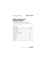
Inside . . .
For See Page
Important User Information 2
Prevent Electrostatic Discharge 3
Environment and Enclosure 4
North American Hazardous Location Approval 5
About the Module 6
Install the Mounting Base 7
Install the Module 8
Install the Removable Terminal Block (RTB) 11
Remove a Mounting Base 12
Wire the Module 14
Configure the Module 18
Troubleshoot the Module 21
Specifications 23

2 POINT I/O Protected Sink Output Module
Publication
1734-IN585C-EN-E - December 2005
Important User Information
Solid state equipment has operational characteristics differing from those of electromechanical
equipment. Safety Guidelines for the Application, Installation and Maintenance of Solid State Controls
(Publication SGI-1.1 available from your local Rockwell Automation sales office or online at
http://www.literature.rockwellautomation.com) describes some important differences between solid
state equipment and hard-wired electromechanical devices. Because of this difference, and also
because of the wide variety of uses for solid state equipment, all persons responsible for applying this
equipment must satisfy themselves that each intended application of this equipment is acceptable.
In no event will Rockwell Automation, Inc. be responsible or liable for indirect or consequential damages
resulting from the use or application of this equipment.
The examples and diagrams in this manual are included solely for illustrative purposes. Because of the
many variables and requirements associated with any particular installation, Rockwell Automation, Inc.
cannot assume responsibility or liability for actual use based on the examples and diagrams.
No patent liability is assumed by Rockwell Automation, Inc. with respect to use of information, circuits,
equipment, or software described in this manual.
Reproduction of the contents of this manual, in whole or in part, without written permission of Rockwell
Automation, Inc., is prohibited.
Throughout this manual, when necessary, we use notes to make you aware of safety considerations.
WARNING
Identifies information about practices or circumstances that can cause an explosion in
a hazardous environment, which may lead to personal injury or death, property
damage, or economic loss.
IMPORTANT
Identifies information that is critical for successful application and understanding of
the product.
ATTENTION
Identifies information about practices or circumstances that can lead to personal
injury or death, property damage, or economic loss. Attentions help you identify a
hazard, avoid a hazard, and recognize the consequences.
S
HOCK HAZARD
Labels may be located on or inside the equipment (for example, drive or motor) to
alert people that dangerous voltage may be present.
BURN HAZARD
Labels may be located on or inside the equipment (for example, drive or motor) to
alert people that surfaces may be dangerous temperatures.

POINT I/O Protected Sink Output Module 3
Publication
1734-IN585C-EN-E - December 2005
Prevent Electrostatic Discharge
ATTENTIO
N
This equipment is sensitive to electrostatic discharge,
which can cause internal damage and affect normal
operation. Follow these guidelines when you handle this
equipment:
• Touch a grounded object to discharge potential static.
• Wear an approved grounding wriststrap.
• Do not touch connectors or pins on component
boards.
• Do not touch circuit components inside the
equipment.
• Use a static-safe workstation if available.
• Store the equipment in appropriate static-safe
packaging when not in use.

4 POINT I/O Protected Sink Output Module
Publication
1734-IN585C-EN-E - December 2005
Environment and Enclosure
ATTENTIO
N
This equipment is intended for use in a Pollution Degree
2 industrial environment, in overvoltage Category II
applications (as defined in IEC publication 60664-1), at
altitudes up to 2000 meters without derating.
This equipment is considered Group 1, Class A industrial
equipment according to IEC/CISPR Publication 11.
Without appropriate precautions, there may be potential
difficulties ensuring electromagnetic compatibility in other
environments due to conducted as well as radiated
disturbance.
This equipment is supplied as open-type equipment. It
must be mounted within an enclosure that is suitably
designed for those specific environmental conditions that
will be present and appropriately designed to prevent
personal injury resulting from accessibility to live parts.
The interior of the enclosure must be accessible only by
the use of a tool. Subsequent sections of this publication
may contain additional information regarding specific
enclosure type ratings that are required to comply with
certain product safety certifications.
Besides this publication, see:
• Industrial Automation Wiring and Grounding
Guidelines, Allen-Bradley publication 1770-4.1, for
additional installation requirements.
• NEMA Standards publication 250 and IEC publication
60529, as applicable, for explanations of the degrees
of protection provided by different types of
enclosure.

POINT I/O Protected Sink Output Module 5
Publication
1734-IN585C-EN-E - December 2005
North American Hazardous Location Approval
The following information applies when
operating this equipment in hazardous
locations:
Informations sur l’utilisation de cet équipement
en environnements dangereux:
Products marked “CL I, DIV 2, GP A, B, C, D” are suitable
for use in Class I Division 2 Groups A, B, C, D, hazardous
locations and nonhazardous locations only. Each product is
supplied with markings on the rating nameplate indicating
the hazardous location temperature code. When
combining products within a system, the most adverse
temperature code (lowest “T” number) may be used to
help determine the overall temperature code of the
system. Combinations of equipment in your system are
subject to investigation by the local Authority Having
Jurisdiction at the time of installation.
Les produits marqués “CL I, DIV 2, GP A, B, C, D” ne
conviennent qu’à une utilisation en environnements de Classe I
Division 2 Groupes A, B, C, D dangereux et non dangereux.
Chaque produit est livré avec des marquages sur sa plaque
d’identification qui indiquent le code de température pour les
environnements dangereux. Lorsque plusieurs produits sont
combinés dans un système, le code de température le plus
défavorable (code de température le plus faible) peut être
utilisé pour déterminer le code de température global du
système. Les combinaisons d’équipements dans le système
sont sujettes à inspection par les autorités locales qualifiées
au moment de l’installation.
EXPLOSION HAZARD -
• Do not disconnect equipment unless
power has been removed or the area
is known to be nonhazardous.
• Do not disconnect connections to
this equipment unless power has
been removed or the area is known
to be nonhazardous. Secure any
external connections that mate to
this equipment by using screws,
sliding latches, threaded
connectors, or other means provided
with this product.
• Substitution of components may
impair suitability for Class I, Division
2.
• If this product contains batteries,
they must only be changed in an
area known to be nonhazardous.
RISQUE D’EXPLOSION –
• Couper le courant ou s’assurer que
l’environnement est classé non
dangereux avant de débrancher
l'équipement.
• Couper le courant ou s'assurer que
l’environnement est classé non
dangereux avant de débrancher les
connecteurs. Fixer tous les
connecteurs externes reliés à cet
équipement à l'aide de vis, loquets
coulissants, connecteurs filetés ou
autres moyens fournis avec ce
produit.
• La substitution de composants peut
rendre cet équipement inadapté à une
utilisation en environnement de
Classe 1, Division 2.
• S’assurer que l’environnement est
classé non dangereux avant de
changer les piles.
WARNING
AVERTISSEMENT

6 POINT I/O Protected Sink Output Module
Publication
1734-IN585C-EN-E - December 2005
About the Module
Use this series C module with the following:
• ControlNet adapters
with RSLogix 5000 software, version 11 or higher
• DeviceNet adapters
• EtherNet/IP adapters
with RSLogix 5000 software, version 11 or higher
• PROFIBUS adapters
Refer to the figure to identify external features of the module.
Interlocking Side
Pieces
DIN Rail Locking
Screw (orange)
RTB Removal Handle
Removable Terminal
Block (RTB)
31830GM
Mounting Base
Mechanical
Keying
(orange)
Module Wiring
Diagram
Module Locking
Mechanism
Insertable I/O
Module
Slide-in Writable Label

POINT I/O Protected Sink Output Module 7
Publication
1734-IN585C-EN-E - December 2005
Install the Mounting Base
To install the mounting base on the DIN rail, proceed as follows.
1. Position the mounting base vertically above the installed units
(adapter, power supply, or existing module).
2. Slide the mounting base down, allowing the interlocking side
pieces to engage the adjacent module or adapter.
3. Press firmly to seat the mounting base on the DIN rail.
The mounting base snaps into place.
ATTENTIO
N
POINT I/O is grounded through the DIN rail to chassis
ground. Use zinc-plated yellow-chromate steel DIN rail to
assure proper grounding. The use of other DIN rail
material (for example, aluminum and plastic) that can
corrode, oxidize, or are poor conductors, can result in
improper or intermittent grounding.
Secure DIN rail to mounting surface approximately every
200 mm (7.8 in.).
Slide the mounting base to
allow the interlocking side
pieces to engage the
adjacent module or
adapter.
31586

8 POINT I/O Protected Sink Output Module
Publication
1734-IN585C-EN-E - December 2005
Install the Module
Install the module before or after base installation. Be sure that you
complete the following.
• Correctly key the mounting base before installing the module
into the mounting base.
• Position the mounting base locking screw horizontal
referenced to the base.
ATTENTIO
N
When you insert or remove the module while backplane
power is on, an electrical arc can occur. This could cause
an explosion in hazardous location installations.
Be sure that power is removed or the area is
nonhazardous before proceeding. Repeated electrical
arcing causes excessive wear to contacts on both the
module and its mating connector. Worn contacts may
create electrical resistance that can affect module
operation.

POINT I/O Protected Sink Output Module 9
Publication
1734-IN585C-EN-E - December 2005
To install the module on the DIN rail, proceed as follows.
1. Use a bladed screwdriver to rotate the keyswitch on the
mounting base clockwise until the number required for the
type of module being installed aligns with the notch in the
base.
2. Be sure the DIN rail locking screw is in the horizontal
position.
If you unlock the locking mechanism, you cannot insert the
module.
44009
Notch
(position 3 shown)
Turn the keyswitch to align the number with the notch.
44010
Make sure the DIN rail
locking screw is in the
horizontal position.

10 POINT I/O Protected Sink Output Module
Publication
1734-IN585C-EN-E - December 2005
3. Insert the module straight down into the mounting base.
4. Press to secure.
The module locks into place.
24VDC
Source
Output
Module
Status
Network
Status
1734
OB4E
NODE:
0
1
2
3
44012
2
4
V
D
C
S
o
u
rc
e
O
u
tp
u
t
M
odule
Status
N
e
tw
o
rk
S
ta
tu
s
1
7
3
4
O
B
4
E
N
O
D
E
:
0
1
2
3
30880

POINT I/O Protected Sink Output Module 11
Publication
1734-IN585C-EN-E - December 2005
Install the Removable Terminal Block (RTB)
A removable terminal block comes with your wiring base. To
remove, pull up on the RTB handle. Remove or replace the
mounting base without removing any of the wiring.
1. Insert the end opposite the handle into the base unit, noting
that this end has a curved section that engages with the wiring
base.
2. Rotate the terminal block into the wiring base until it locks
itself in place.
3. If you installed an I/O module, snap the RTB handle into
place on the module.
WARNING
When you connect or disconnect the removable terminal
block (RTB) with field-side power applied, an electrical
arc can occur. This could cause an explosion in hazardous
location installations.
Be sure that power is removed or the area is
nonhazardous before proceeding.
44011

12 POINT I/O Protected Sink Output Module
Publication
1734-IN585C-EN-E - December 2005
Remove a Mounting Base
To remove a module from the DIN rail, remove any installed module
and the module installed in the base to the right. Remove the
removable terminal block, if wired.
1. Unlach the RTB handle on the I/O module.
2. Pull on the RTB handle to remove the removable terminal
block.
3. Press on the module lock on the top of the module.
WARNING
When you connect or disconnect the removable terminal
block (RTB) with field-side power applied, an electrical
arc can occur. This could cause an explosion in hazardous
location installations.
Be sure that power is removed or the area is
nonhazardous before proceeding.

POINT I/O Protected Sink Output Module 13
Publication
1734-IN585C-EN-E - December 2005
4. Pull on the I/O module to remove from the base.
5. Repeat steps 1, 2, 3, and 4 for the module to the right.
6. Use a small-bladed screwdriver to rotate the orange base
locking screw to a vertical position.
This releases the locking mechanism on the mounting base.
7. Lift straight up to remove the mounting base.
ATTENTIO
N
When you insert or remove the module while backplane
power is on, an electrical arc can occur. This could cause
an explosion in hazardous location installations.
Be sure that power is removed or the area is
nonhazardous before proceeding. Repeated electrical
arcing causes excessive wear to contacts on both the
module and its mating connector. Worn contacts may
create electrical resistance that can affect module
operation.

14 POINT I/O Protected Sink Output Module
Publication
1734-IN585C-EN-E - December 2005
Wire the Module
Refer to the figures to wire the module.
WARNING
If you connect or disconnect wiring while the field-side
power is on, an electrical arc can occur. This could cause
an explosion in hazardous location installations. Be sure
that power is removed or the area is nonhazardous before
proceeding.
IMPORTANT
To comply with the CE Low Voltage Directive (LVD), I/O
must be powered from a source compliant with the
following: Safety Extra Low Voltage (SELV) or Protected
Extra Low Voltage (PELV).
Module Status
Network Status
Status of Output 0
Status of Output 1
Status of Output 2
Output 1
1734-OV2E 1734-OV4E
C = Common
V = Supply
4202942028
24VDC
Sink
Output
Module
Status
Network
Status
1734
OV8E
NODE:
0
1
2
3
4
5
6
7
1734-OV8E
42030
Status of Output 0 & 4
Status of Output 1 & 5
Status of Output 2 & 6
Status of Output 3 & 7
Output 3
Output 5
Output 7
Output 1
N/C
C
V
Output 0
Output 2
Output 4
Output 6
Output 1
Output 3
V
V
Output 0
Output 2
V
V
Output 0
N/C
C
V
Status of Output 3
24VDC
Sink
Output
Module
Status
Network
Status
1734
OV4E
NODE:
0
1
2
3
2
24VDC
Sink
Output
Module
Status
Network
Status
1734
OV2E
NODE:
0
1

POINT I/O Protected Sink Output Module 15
Publication
1734-IN585C-EN-E - December 2005
Output
Terminal
Power Common
Terminal
Channel 0 0 6 4
Channel 1 1 7 5
Module power is supplied from the internal power bus.
Out 0
Out 1
N/C
N/C
C
C
V
V
Load
Load
42014
V = 12/24V dc, C = Common
Field power is supplied from internal power bus.
1734-OV2E
0
2
6
4
3
5
7
1

16 POINT I/O Protected Sink Output Module
Publication
1734-IN585C-EN-E - December 2005
Output
Termina l
Power Common
Terminal
Channel 0 0 6
Channel 1 1 7
Channel 2 2 4
Channel 3 3 5
Module power is supplied from the internal power bus.
Out 0 Out 1
Out 3Out 2
V
V
V
V
Load
Load
42015
Load
Load
V = 12/24V dc, C = Common
Field power is supplied from internal power bus.
1734-OV4E
0
2
6
3
1
7
45

POINT I/O Protected Sink Output Module 17
Publication
1734-IN585C-EN-E - December 2005
Channel
Number
Output
Termina l
Common Terminal Power
Channel 0 0 Common is daisychained
from either a 1734 adapter,
1734-FPD, 1734-EP24DC, or
from a user-supplied
external terminal block.
The 24V dc power for the
module is supplied by the
internal power bus and
originates from the same
adapter, 1734-FPD, or
1734-EP24DC as common.
Channel 1 1
Channel 2 2
Channel 3 3
Channel 4 4
Channel 5 5
Channel 6 6
Channel 7 7
Module power is supplied from the internal power bus.
Out 0
Out 1
Out 3
Out 2
Load
Load
42015
Load
C
ommon must be daisychained from a 1734 adapter, 1734-FPD, 1734-EP24DC, or from a
u
ser-supplied external terminal block. The 24V dc power to the module is supplied by the internal
p
ower bus and comes from the same 1734 adapter, 1734-FPD, or 1734-EP24DC as common.
1734-OV8E
0
2
6
3
1
7
4
5
Load
Load
Load
Load
Load
Out 4
Out 5
Out 7
Out 6
V
V

18 POINT I/O Protected Sink Output Module
Publication
1734-IN585C-EN-E - December 2005
Configure the Module
POINT I/O modules send (consume) and receive (produce) I/O
messages. You map these messages into the processor memory. This
POINT I/O output module produces 1 byte of input data (scanner Rx)
(status). It consumes 1 byte of I/O data (scanner Tx).
System
Power
DeviceNet
Power
Network
Status
Module
Status
1734
IB8
3
2
0
1
7
6
4
5
Network
Status
Module
Status
1734
OB8E
3
2
0
1
7
6
4
5
24V dc
24V dc Return
Load
Load
Load
Load
Load
Load
Load
Load
Notes:
The 1734-OB8E maximum load is
1A maximum per channel, and 3A
total per module.
Terminal Block with
Bus connector strip
DeviceNet
Example of Wiring for the 1734-OV8E Output Module
The 1734-OV8E maximum load is
1 A min per channel, and
3 A total per module.
44023
1734-
IV8
1734-
OV8E
Terminal Block with Bus Connector Strip

POINT I/O Protected Sink Output Module 19
Publication
1734-IN585C-EN-E - December 2005
Default Data Map for the 1734-OV2E Output Module
Message size: 1 Byte
Message size: 1 Byte
Default Data Map for the 1734-OV4E Output Module
Message size: 1 Byte
Message size: 1 Byte
76543 2 1 0
Produces
(scanner Rx)
Not used Ch1 Ch0 Channel status
Where: 0 = no error, 1 = error
76543 2 1 0
Consumes
(scanner Tx)
Not used Ch1 Ch0 Channel state
Where: 0 = Off, 1 = On
76543 2 1 0
Produces
(scanner Rx)
Not used Ch3 Ch2 Ch1 Ch0 Channel
status
Where: 0 = no error, 1 = error
76543 2 1 0
Consumes
(scanner Tx)
Not used Ch3 Ch2 Ch1 Ch0 Channel
state
Where: 0 = Off, 1 = On

20 POINT I/O Protected Sink Output Module
Publication
1734-IN585C-EN-E - December 2005
Default Data Map for the 1734-OV8E Output Module
Message size: 1 Byte
Message size: 1 Byte
76543210
Produces
(scanner Rx)
Ch7 Ch6 Ch5 Ch4 Ch3 Ch2 Ch1 Ch0 Channel
status
Where: 0 = no error, 1 = error
76543210
Consumes
(scanner Tx)
Ch7 Ch6 Ch5 Ch4 Ch3 Ch2 Ch1 Ch0 Channel
state
Where: 0 = no error, 1 = error
/