Page is loading ...

D13728.09 Page 1
Installation
3000/6000 Profile
For mounting of the Wheel base, Foot mount or Wall mount, follow the respective instructions on page 2-6.
2 Mounting
Wheel base Foot mount Wall mount
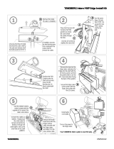
1 Unpacking
Monitor
Bolts:
Wall Bracket
Camera
Top Module
Cable Cover, Back
Cover and Base
(Wheel base option)
Camera Stand
Column
and Foot
2x Type A 2x Type B
4x Type C
4x Type D
+ 4x plugs for concrete
Wrench
Remote
Control
Screw driver
(for removing the handles
on 6000 MXP Profile 50”)
User Manual on CD
4x Type E
+ 4x washers for
gypsum/plasterboard
For mounting of the Wheel base, Foot mount or the Wall mount version,
follow the respective instructions on the following pages.

D13728.09 Page 2
Wheel base
1 Disassemble the Foot from the Column.
Keep the bolts
2 Assemble the Column to the Base with
the 8 bolts from the Foot
3 Mount the Top Module to the Column
1)
Use 4x type C
bolts in front
and on sides
from
underneath.
2)
Use 2x type B
bolts behind,
from above.
Remove rubber band
before mounting.
Remove protection
foil from acrylic plate.
4 Lift the Monitor onto the Top Module and
connect cables
Align according to
arrow labels and lower
the Monitor into place.
Connect power
cable and DVI cable
from Top Module to
Monitor after mounting
the Monitor. Also connect
speaker and amplier cables.
Put excess cable length back behind monitor.
5a Mount the Monitor 43”/50”, for 32” see 5b
On all products, except
TANDBERG 3000
MXP 32” Prole:
Use 2x type A
bolts to xate the
Monitor.
Caution! Be careful not to squeeze ngers or cables.
Rearrange cables if necessary.
Keep the Column in the
package upside down
while disassembling
the Foot.
WARNING! Do not lift
the Column out of the
package, the small
pegs on the
Column may
dent the oor.
Assemble the Base
while the Column
stands in the package
upside down.
Then, lift the Column
and the Base out of the
package.
5b Mount the Monitor 32”
On TANDBERG
3000 MXP 32”
Prole:
Tighten the bolts
on each side of the
rear structure to
xate the Monitor.
3000/6000 Profile

7 Mount the Camera
Pull cable through Camera Stand, and
place it behind the Monitor.
Ensure that the Camera Stand is prop-
erly connected to the magnets on top
and behind. Plug cable to Camera as
shown on gure above.
Place Camera on top. The guide pin
and magnets will ensure correct place-
ment. Please verify that the Camera is
aligned with the front line of the Monitor.
D13728.09 Page 3
Wheel base
Mount the Magnet Brackets behind the
Column and attach the Cable Cover to
the magnets. You may have to
rearrange the cables.
Mount the Back Cover on the back side
of the Top Module.
6 Mount the Cable Cover and the Back Cover
8 Connecting external devices
If external deivces are
connected to the system,
lead the cables through
the hole in the cable
cover.
3000/6000 Profile
There are access holes
provided near the base
of the column section for
cable access to the front
DVD/VCR tray and to the
rollabout base for cables
that must run to the oor.
HD VIDEO
OUT CODEC

D13728.09 Page 4
Foot mount
Warning!
Due to the size and mass of this equipment, it is very important that the wall mount unit is safely installed according to
these installation instructions and that the wall is able to safely support the product. It is highly recommended that this
Foot mount unit is installed by trained personnel.
1 A) Mount the Wall Bracket to the wall
- Studs/pillars
Make sure that the hooks
on the Wall Bracket
point upwards.
Mount 762 mm
(30”)
horizontally from
oor to underneath
wall-mount.
Use 4 type D bolts.
Make sure to select holes
that align with the wall
studs/pillars.
1 C) Mount the Wall Bracket to the wall
- Brick/Concrete wall
Make sure that the hooks
on the Wall Bracket
point upwards.
Mount 762 mm
(30”)
horisontally from
oor to underneath
wall-mount.
Use 4 type D bolts
with concrete plugs.
1. Drill a small
initial hole
2. Drill a larger
hole for plugs
3. Mount into
specied
holes with
plugs and
bolts.
2 Mount the Top Module and the column to the Wall
Bracket
Step 1
Use 2x type B
bolts behind
from above
Use 4x type C
bolts in front
and on sides
from underneath.
Remove rubber
band before
mounting.
Remove protection
foil from acrylic plate.
Step 2
Tighten nuts in
position
a and b after
mounting.
3 Connect cables and mount the Monitor
Pull cable through
Camera Stand, and
place it behind the
Monitor. Ensure that the
Camera Stand is
properly connected
to the magnets on top
and behind.
Plug cables to Camera
and place camera on
top with velcro.
Disassemble the handles
at the back of the screen
with the screw driver.
(6000 MXP Prole only)
4 Mount the Camera
762 mm
(30
”
)
762 mm
(30”)
Caution! Be careful not to squeeze ngers or cables.
Rearrange cables if necessary.
3000/6000 Profile
1 B) Mount the Wall Bracket to the wall
- Drywall/plasterboard with minimum
thickness 13mm (1/2”)
Follow the same procedure as described in
1A) but use 4 type E bolts with 4 washers.
Drill a hole (Ø6,0mm / 1/4”) for the plug
and then fasten the type E bolts with washers.
Ø3,0mm
(1/8”)
Ø10,0mm
(3/8”)
75,0mm
(3.0”)
(Please note that the 32” Monitor
shall be mounted
as described in
5b on page 2).
Connect power
cable and DVI
cable from Top
Module to Monitor
before mounting
the Monitor.
Align according to arrow lables
and lower the Monitor into place.
Put excess cable length back behind Monitor.
HD VIDEO
OUT CODEC
2
1
a
b

Caution! Be careful not to squeeze ngers or cables.
Rearrange cables if necessary.
D13728.09 Page 5
Wall mount
Warning!
Due to the size and mass of this equipment, it is very important that the wall mount unit is safely installed according to
these installation instructions and that the wall is able to safely support the product. It is highly recommended that this wall
mount unit is installed by trained personnel.
According to Standard IEC60950 3rd ed. the wall is required to support four times the actual load, which implies that a
TANDBERG MXP Prole system must be mounted to a wall which supports:
4x 77kg=308kg/679 lbs (T6000 50”), 4x 61kg=244kg/538 lbs (T3000 42”) and 4x 49kg=196kg/432 lbs (T3000 32”).
1 A) Mount the Wall Bracket to the wall
- Studs/pillars
Make sure that the hooks
on the Wall Bracket
point upwards.
Mount the Wall Bracket
horisontally in desired
hight from oor,
recommended
762 mm (
30
”).
It is important that the
bracket is fastened to the
studs/pillars, using 4 type
D bolts.
Make sure to select holes
that align with the wall
studs/pillars
1 B) Mount the Wall Bracket to the wall
- Brick/Concrete wall
Make sure that the hooks
on the Wall Bracket
point upwards.
Mount the Wall
Bracket horisontally
in desired hight from
oor, recommended
762 mm (30”).
Use 4 type D bolts
with concrete plugs.
1. Drill a small
initial hole
2. Drill a larger
hole for plugs
3. Mount into
specied
holes with
plugs and
bolts.
Pull cable through
Camera Stand, and
place it behind the
Monitor. Ensure that the
Camera Stand is
properly connected
to the magnets on top
and behind.
Plug cables to Camera
and place camera on
top with velcro.
4 Mount the Camera
2 Mount the Top Module to the Wall Bracket
Tighten nuts
in position
a and b after
mounting.
3 Connect cables and mount the Monitor
762 mm
(30”)
�3,0�mm
(0,1”)
�10,0�mm
(0,4”)
75�mm
(3,0”)
3000/6000 Profile
(Please note that the 32” Monitor
shall be mounted
as described in
5b on page 2).
Connect power
cable and DVI
cable from Top
Module to Monitor
before mounting
the Monitor. Also connect
speaker and amplier cables.
Align according to arrow lables
and lower the Monitor into place.
Put excess cable length back behind Monitor.
762 mm
(
30”
)
HD VIDEO
OUT CODEC
a
b

Touch tonesSnapshot
Camera Presets
D13728.09 Page 6
Installation
2. Language
Open ‘General’. Select language and press save.
3b. ISDN Conguration
Open ‘Network - ISDN Settings’. Select ISDN-BRI
Settings or ISDN-PRI Settings. Make ISDN conguration
and press ‘Save’.
1. Open the Control Panel
Choose ‘Control Panel’ from the main menu and
press OK.
3 System Conguration
3a. LAN Conguration
Open ‘Network - LAN Settings’. Make IP/H.323
conguration and press ‘Save’.
Please read the user manual for further details.
TIP
If the menu is not already present, press the
OK/Menu key on the remote control
to open the menu. Navigate the menu
with arrow keys and OK
OK/Menu
button
3000/6000 Profile
/