
www.eaton.com
Power Xpert
®
Meter 4000/6000/8000
Quick Start Guide
Instruction Booklet IB02601007E
Effective January 2017
Supercedes January 2012

Copyright © 2017 by Eaton. All rights reserved.
Specifications and information contained herein are subject to change
without notice.
Power Xpert and PowerVision are registered trademarks of Eaton.
EATON - CONFIDENTIAL AND PROPRIETARY NOTICE TO PERSONS RE-
CEIVING THIS DOCUMENT AND/OR TECHNICAL INFORMATION
THIS DOCUMENT, INCLUDING THE DRAWING AND INFORMATION
CONTAINED THEREON, IS CONFIDENTIAL AND IS THE EXCLUSIVE
PROPERTY OF EATON, AND IS MERELY ON LOAN AND SUBJECT TO
RECALL BY EATON AT ANY TIME. BY TAKING POSSESSION OF THIS
DOCUMENT, THE RECIPIENT ACKNOWLEDGES AND AGREES THAT
THIS DOCUMENT CANNOT BE USED IN ANY MANNER ADVERSE TO
THE INTERESTS OF EATON, AND THAT NO PORTION OF THIS DOCU-
MENT MAY BE COPIED OR OTHERWISE REPRODUCED WITHOUT THE
PRIOR WRITTEN CONSENT OF EATON. IN THE CASE OF CONFLICT-
ING CONTRACTUAL PROVISIONS, THIS NOTICE SHALL GOVERN THE
STATUS OF THIS DOCUMENT.
DISCLAIMER OF WARRANTIES AND LIMITATION OF LIABILITY
The information, recommendations, descriptions and safety notations in
this document are based on Eaton Electrical Inc. and/or Eaton’s (“Eaton”)
experience and judgment and may not cover all contingencies. If further
information is required, an Eaton sales office should be consulted.
Sale of the product shown in this literature is subject to the terms and
conditions outlined in appropriate Eaton selling policies or other contrac-
tual agreement between Eaton and the purchaser.
THERE ARE NO UNDERSTANDINGS, AGREEMENTS, WARRANTIES,
EXPRESSED OR IMPLIED, INCLUDING WARRANTIES OF FITNESS FOR
A PARTICULAR PURPOSE OR MERCHANTABILITY, OTHER THAN THOSE
SPECIFICALLY SET OUT IN ANY EXISTING CONTRACT BETWEEN THE
PARTIES. ANY SUCH CONTRACT STATES THE ENTIRE OBLIGATION OF
EATON. THE CONTENTS OF THIS DOCUMENT SHALL NOT BECOME
PART OF OR MODIFY ANY CONTRACT BETWEEN THE PARTIES.
In no event will Eaton be responsible to the purchaser or user in contract,
in tort (including negligence), strict liability or otherwise for any special,
indirect, incidental or consequential damage or loss whatsoever, includ-
ing but not limited to damage or loss of use of equipment, plant or power
system, cost of capital, loss of power, additional expenses in the use of
existing power facilities, or claims against the purchaser or user by its
customers resulting from the use of the information, recommendations
and descriptions contained herein.

Table of Contents
1. Introduction ........................................................................... 5
1.1. Safety Precautions ................................................................ 5
2. Quick Start Guide for the Meter .......................................... 7
2.1. Safety Precautions ............................................................... 7
2.2. Power Supply Connections.................................................. 8
2.3. Configure the Security Mode Dip Switches ........................ 9
2.4. Com Reset Switch ............................................................. 10
2.5. Base Address .................................................................... 10
2.6. VT , VX, and CT Connections ........................................... 10
2.7. Establishing Communications between the Meter
and the Displays ................................................................11
2.8. Connecting to a Meter Using the Embedded Web
Server Interface ................................................................. 12
2.9. Programming the Meter via the Optional
Communications Expansion Card ...................................... 13
3. Mounting and Wiring ......................................................... 17
3.1. Mounting the Meter and Displays ..................................... 17
3.2. General Instructions .......................................................... 17
3.3. Wiring ................................................................................ 18
3.4. Fuses ................................................................................. 21
3.5. Hipot and Megohm (Megger) Testing ................................ 21
3.6. Communication Wiring ...................................................... 21
3.7. RS485 Network ................................................................. 22
3.8. RS485 Cable Characteristics ............................................. 22
3.9. RS485 Wiring Basics ......................................................... 22
4. Ratings ................................................................................ 25
4.1. Environmental Ratings ....................................................... 25
4.2. PowerXpert I/O Board (PXMIO Card) ................................. 25
4.3. Electrical Ratings ............................................................... 25
4.4. Meter and Display Cleaning instructions ........................... 26


1. Introduction
1.1. Safety Precautions
All safety codes, safety standards and/or regulations must be strictly observed in the
installation, operation and maintenance of this device.
WARNINGS refer to a hazardous situation which, if not avoided, could result in death or
serious injury.
CAUTIONS refer to a hazardous situation which, if not avoided, could result in equipment
damage.
WARNINGS
SHOCK HAZARDS:
IMPROPER INSTALLATION CAN CAUSE DEATH, INJURY AND/OR EQUIPMENT
DAMAGE. Follow all Warnings and Cautions. Completely read and understand the infor-
mation in this document before attempting to install or operate the equipment. Improper
wiring could cause death, injury and/or equipment damage. Only qualied personnel are
to service the Power Xpert
®
Meter.
TROUBLESHOOTING PROCEDURES MAY REQUIRE PROXIMITY TO EXPOSED
ENERGIZED (LIVE) ELECTRICAL WIRING AND/OR PARTS WHERE THE HAZARD OF
FATAL ELECTRIC SHOCK IS PRESENT.
Exercise extreme care to avoid injury or death. Always disconnect, lock-out and tag the
current and voltage sources and the control power supply circuit before touching the con-
nections or components on the rear face of the meter.
FAILURE TO GROUND THE POWER XPERT
®
METER MAY RESULT IN INJURY, DEATH
OR EQUIPMENT DAMAGE.
Properly ground the Power Xpert
®
Meter during installation.
www.eaton.com IB02601007E Page 5
1. Introduction

Page 6 IB02601007E www.eaton.com
1. Introduction

www.eaton.com IB02601007E Page 7
2. Quick Start Guide for the Meter
2. Quick Start Guide for the Meter
2.1. Safety Precautions
All safety codes, safety standards and/or regulations must be strictly observed in the
installation, operation and maintenance of this device.
WARNINGS refer to instructions that, if not followed, can result in death or injury.
CAUTIONS refer to instructions that, if not followed, can result in equipment
damage.
WARNINGS
SHOCK HAZARDS:
IMPROPER INSTALLATION CAN CAUSE DEATH, INJURY AND/OR EQUIPMENT
DAMAGE. Follow all Warnings and Cautions. Completely read and understand the infor-
mation in this document before attempting to install or operate the equipment. Improper
wiring could cause death, injury and/or equipment damage. Only qualied personnel are
to service the Power Xpert Meter 4000/6000/8000 and displays.
TROUBLESHOOTING PROCEDURES MAY REQUIRE PROXIMITY TO EXPOSED
ENERGIZED (LIVE) ELECTRICAL WIRING AND/OR PARTS WHERE THE HAZARD OF
FATAL ELECTRIC SHOCK IS PRESENT. Exercise extreme care to avoid injury or death.
Always disconnect, lock-out, and tag the current and voltage sources and the control
power supply circuit before touching the connections or components on the rear face of
the Power Xpert Meter 4000/6000/8000 and displays.
FAILURE TO GROUND THE POWER XPERT METER MAY RESULT IN DEATH, IN-
JURY OR EQUIPMENT DAMAGE. Properly ground the Meter during installation.
IMPROPER ASSEMBLY AND INSTALLATION OF THE CT TERMINAL BLOCK AND
STRAIN RELIEF HOOD MAY RESULT IN OPEN CIRCUITED CTS AND EXPOSURE TO
DANGEROUS VOLTAGES WHICH MAY RESULT IN SEVERE INJURY OR DEATH.
Terminal block hoods are provided with the metering current and voltage terminal blocks.
The current terminal block retaining screws are part of the matching hood assembly. The
current terminal block and hood assembly must be properly installed with retaining screws
to secure the current terminal block to the meter housing to prevent exposure to shock
hazard.

Page 8 IB02601007E www.eaton.com
2. Quick Start Guide for the Meter
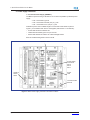
2.2. Power Supply Connections
1. Connect the Power Supply (PXMPS-1)
The Meter is powered using a 100-240 Vac or 110-250 Vdc (PXMPS-1) standard power
supply.
• PS1-3 connected to ground
• PS1-2 connected to Neutral (Vac) or (-) Vdc
• PS1-1 connected to Line (Vac) or (+) Vdc
Fabricate a power cord of suitable length to connect PS1-1/PS1-2/PS1-3 (refer to
Figure 1) to a suitable Power Source that supplies (100-240 Vac or 110-250 Vdc).
• Power LED should be solid blue ON.
• Health LED should blink green once per second.
• Status LED will blink red if there are unacknowledged events.
Refer to Troubleshooting Section in this manual.
PXMPS-1 Card
Power Supply
Connection
PS1-3
PS1-2
PS1-1
Health &
Status
LEDs
Figure 1: Meter Power Supply Connection and LED Locations.
Power
LED
Protective Earth
Ground

www.eaton.com IB02601007E Page 9
2. Quick Start Guide for the Meter
2.3. Congure the Security Mode Dip Switches
Figure 2: Meter’s Dip Switches and Tamper Seals.
Tamper Seals
DIP Switches
ON
OFF
DS-1 DS-2 DS-3
OFF OFF
ON is
Normal.
OFF is
Safe
Mode.
No restrictions (user ID/Password re-
quired)
ADMIN/ADMIN accepted for 15 minutes
after boot-up
OFF ON
ON is
Normal.
OFF is
Safe
Mode.
Medium Security - Energy & Demand
resets prohibited
ON OFF
ON is
Normal.
OFF is
Safe
Mode.
High Security- Conguration changes;
Energy & Demand reset prohibited
ON ON ON or
OFF.
Factory Test Mode - The meter should
never be operated in this mode. The meter
will indicate that it’s in factory test mode
through a repeating series of three ashes
on the red Status LED

Page 10 IB02601007E www.eaton.com
2. Quick Start Guide for the Meter
2.4. Com Reset Switch
Located above the rotary switch, the Com Reset switch can be used in conjunction with
the DIP switches on the power supply front panel to reset the meter’s communications
ports. The reset switch has the following functions, depending on the DIP switch settings.
DS -1 DS-2 DS-3
OFF OFF ON Initialize all communications ports to their
factory default settings.
OFF ON ON Initialize the LAN/WAN and Local Cong
communications ports and assign the fol-
lowing IP addresses:
LAN/WAN: 10.1.1.1
Local Cong: 192.168.1.1
ON OFF ON Attempt to recover communications via
the LAN/WAN port by disabling then re-
enabling the communications port.
ON ON ON or
OFF
Factory Test Mode - The meter should
never be operated in this mode. The
meter will indicate that it’s in factory test
mode through a repeating series of three
ashes on the red Status LED.
Refer to the User and Installation Manual (IM02601004E) for more information.
2.5. Base Address
The Power Xpert Meter has a rotary Base Address switch on the bottom-left side of the
meter. This rotary switch is for use with the obsolete PXD-MMG on COM0 and does not
apply to COM1, COM2, or COM3.
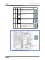
2.6. VT , VX, and CT Connections
Planning CT and VT Connections (Figure 3)
Determine your wiring requirements for the meter. This quick start guide will cover these
basic wiring congurations:
• 3-Phase, 3-Wire Delta( Up to 600 V L-L, 347 L-N) 3 CTs
• 3-Phase, 3-Wire Delta (Above Up to 600 V L-L, 347 L-N) 3 CTs
• 3-Phase, 3-Wire Delta (Above Up to 600 V L-L, 347 L-N) 2 CTs
• 3-Phase,4-Wire Y (Up to Up to 600 V L-L, 347 L-N)
• 3-Phase,4-Wire Y (Above Up to 600 V L-L, 347 L-N)
See Wiring Diagrams in this manual for examples of CT and PT connections.
VT Terminal Voltage Connections:
Voltage Inputs can accept up to 600 Vac L:L / 347VL:G direct. A PT with a 120 V second-
ary is required if this rating is exceeded. Primary settings are 120-500,000, for a PT ratio
of 120:120 to 500000 to 120. It is strongly recommended that the Voltage Inputs be con-
nected to the Meter by way of properly rated disconnect switches.

www.eaton.com IB02601007E Page 11
2. Quick Start Guide for the Meter
• VTV1 = Line 1 or Va
• VTV2 = Line 2 or Vb
• VTV3 = Line 3 or Vc
• VTV4 = Line 4 or Vn (neutral)
• VTVR = Metering Reference Ground
VX Optional Auxiliary Voltage Connections:
• VXV6 = Line 1’ or Va2
• VXV7 = Line 2’ or Vb2
• VXV8 = Line 3’ or Vc2
CT Terminal Connections:
Current Inputs accepts a 5-amp secondary with available Primary settings of 5-9999, for a
CT ratio of 5:5 to 9999:5. It is strongly recommended that the Current Inputs be connect-
ed to the Meter by way of a shorting block.
• Line 1 CT connected to Terminals 11 (polarity mark) & 12 (return)
• Line 2 CT connected to Terminals 21 (polarity mark) & 22 (return)
• Line 3 CT connected to Terminals 31 (polarity mark) & 32 (return)
• Neutral CT connected to Terminals 41 (polarity mark) & 42 (return)
• Ground CT connected to Terminals 51 (polarity mark) & 52 (return)
2.7. Establishing Communications between the Meter and the Displays
1. 6-inch color touchscreen display: See TD150015EN (available on the Eaton website,
www.eaton.com/meters) for instructions on how to connect the 6-inch display to the Meter.
2. 12-inch advanced color touchscreen display: See TD150019EN (available on the Eaton
website, www.eaton.com/meters) for instructions on how to connect the 12-inch display to
the Meter.
Figure 3: CT and VT Connections.
VX Connections
CT Connections
VT Connections

Page 12 IB02601007E www.eaton.com
2. Quick Start Guide for the Meter
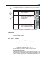
2.8. Connecting to a Meter Using the Embedded Web Server Interface
NOTE: The set up of the Ethernet ports on the CE card must be done through the local
conguration port of the CM card or with the display. After the CE Ethernet port is cong-
ured, the meter can be programmed remotely through the LAN/WAN connection.
1. Connecting a laptop to the meter using the local Ethernet browser interface CM1:
A. Connect the Laptop to the Meter via CM1 port (see Figure 4 below) using a
UTP Cat5 Patch Cable. Note that the IP address of the CM1 port is cong-
ured to be 192.168.1.1.
B. Set the laptop’s IP address to 192.168.1.100 by completing the following
steps:
• Click Window’s Start. Then click Settings. Navigate to the Control Panel of
your computer.
• In Control Panel, click Network and right-click Local PC Area Connection.
Select Properties from the shortcut menu.
• In the Properties dialog, select Internet Protocol (TCP/IP) and click the Proper-
ties button.
• In the Internet Protocol (TCP/IP) Properties window, select “Use the follow-
ing IP address” and then enter the following IP address 192.168.1.100, with a
Subnet Mask set to 255.255.255.0.
• Click OK.
Launch a web browser and then navigate to http://192.168.1.1, then go to
Step 2 in Section 2.9.
NOTES: When connected to a laptop, the Link LED will illuminate and, when communi-
cating, the TXRX LED will icker.
For PXCM Cards, the local conguration port may require the use of a UTP Cat 5 cross
over cable. The PXMCM card accepts a standard Cat 5 patch cable.
Figure 4: Connect Laptop to Meter.
Link LED CM1
TXRX LED

www.eaton.com IB02601007E Page 13
2. Quick Start Guide for the Meter
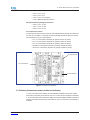
2.9. Programming the Meter via the Optional Communications Expansion Card
The Optional Communications Expansion (CE) card (see Figure 5 below) provides LAN/
WAN Web Ethernet communication via either Fiber (CE1) or UTP/STP Cat5 cable (CE2).
It also provides communication via Modbus RTU (CE3 & CE4 - see Appendix A of the
manual for Modbus instructions).
Note: The CE card is generally installed by the factory at time of manufacture. If the card
is installed as an after sale option, follow instructions for physical installation that accom-
pany the card or refer to the User and Installation Manual (IM02601004E). To set up the
card, follow these steps:
A. The PXMCE ships with CE2 enabled for DHCP. Once connected to the Lo-
cal Area Network supporting DHCP, an IP will be assigned (this may require
a power cycle to the PXM4/6/8K). Once energized, the PXMCE CE1/CE2
port LED “DH” will be illuminated. The assigned IP address for PXMCE
CE1/CE2 can be determined either through an attached display (PXM468K-
DISP-12 or legacy PXD-MMG) or by using the CM1 “Local Conguration”
web server interface.
B. If the PXM4/6/8k was ordered without the PXMCE and is now being in-
stalled, follow the instructions that accompany the PXMCE or refer to Power
Xpert PXM 4000/6000/8000 User and Installation Manual IM02601004E.
C. The PXMCE CE1/CE2 Ethernet settings can be modied by accessing the
PXM4/6/8k CM1 “Local Conguration” web server interface. This will be
required if DHCP will not be used.
D. Power cycle the PXM4/6/8k to initiate DHCP.
CE 1
Figure 5: Ethernet and Modbus Connections.
CE Card
CE 2
CE 3
CE 4

Page 14 IB02601007E www.eaton.com
2. Quick Start Guide for the Meter
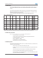
For further details about the following steps, refer to Meter Settings using the Web Server,
in the User and Installation Manual (IM02601004E).
1. Open a web browser. After “http:\\”, type in the IP address of the CE Ethernet port in
the address box and click OK. The Meter Webserver Home Page will be displayed. (If
DHCP is enabled, the user must nd the IP address via the Local Conguration port
[Setup->Diagnostics->Communication->Ethernet Status] or Local Display).
2. Enter the Username and Password. The defaults are: Username = admin and Pass-
word = admin. After entering the Username and Password, click Log In. After clicking
Log In, you will be asked to change the admin password.
3. On the Meter Webserver home page, click Settings, then Quick Setup to display basic
conguration setup.
4. Click Edit to make changes to these parameters.

www.eaton.com IB02601007E Page 15
2. Quick Start Guide for the Meter
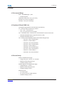
5. Set the clock by clicking on Settings > Clock > Edit.
Notes on Modbus support:
The Optional Communications Expansion (CE) card also provides communication via
Modbus RTU (CE3 & CE4 - see the User and Installation manual [IM02601004E] for Mod-
bus instructions). The RS485 CE3 port supports Modbus RTU slave to a master monitor-
ing system. The port defaults as a Master Gateway, which relays Ethernet Modbus TCP
command to slave meters connected to the same RS485 link. The Modbus slave address
may be set via the Display or with a web browser.

Page 16 IB02601007E www.eaton.com
2. Quick Start Guide for the Meter

3. Mounting and Wiring
WARNING
SHOCK HAZARD: VERIFY THAT ANY INCOMING AC POWER OR FOREIGN POWER
SOURCES ARE TURNED OFF AND LOCKED OUT BEFORE PERFORMING ANY WORK
ON THE POWER XPERT 4000/6000/8000 METER OR ASSOCIATED EQUIPMENT. FAIL-
URE TO DO SO CAN RESULT IN INJURY TO PERSONNEL OR DAMAGE TO EQUIPMENT.
The Power Xpert Meter 4000/6000/8000 is designed to be installed, operated and main-
tained by adequately trained personnel. These instructions do not include all details, varia-
tions or combinations of the equipment, its storage, delivery, installation, checkout, safe
operation or maintenance. Compliance with local, state and national regulations, as well
as with industry standard safety practices for this class of equipment, is imperative. This
section describes mounting, wiring, startup and miscellaneous details associated with the
Power Xpert Meter 4000/6000/8000. Every section should be reviewed prior to installing
this device.
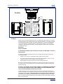
3.1. Mounting the Meter and Displays
1. To mount the Meter directly to a at panel, as recommended, a panel cutout is not nec-
essary. There are eight hole locations on the Meter Mounting Brackets; four circular
holes and four keyholes. Use either set for mounting. See the Meter gure on page
18 for the hole sizes and locations.
2. To mount the 6-inch color touchscreen display, see TD150015EN (available on the
Eaton website, www.eaton.com/meters).
3. To mount the 12-inch advanced color touchscreen display, see TD150019EN (available
on the Eaton website, www.eaton.com/meters).
4. To mount the 6-inch display and the Meter back-to-back, see IL150006EN (available
on the Eaton website, www.eaton.com/meters) for information on the Back to Back
Meter to Display Projection Mount Adapter Kit.
Note: Only the 6-inch display can be mounted back-to-back with the meter, the 12-
inch display must be mounted separately.
3.2. General Instructions
It is recommended that the Power Xpert 4000/6000/8000 Meter be mounted in an electri-
cal switchgear enclosure that is suitable for its environment. The Power Xpert Display and
Meters are generally mounted separately (see manual for mounting together). While it
is recommended that the Display be door or panel mounted, the Meter can be mounted
remotely from the Display on a at surface or panel elsewhere in the enclosure.
• The Meter must remain vertical at all times to maintain proper ventilation.
• The Display and Meter may be installed in a Pollution Degree II environment.
• If the Meter is mounted remotely, the Display MUST be connected to earth ground.
• The Meter should be protected from accidental contact with live terminals in the enclo-
sure. A 1/8 inch steel panel or door, solidly grounded, is recommended.
• The Meter comes standard with the remote mounting brackets attached.
• The Display comes standard with the required hardware for mounting the unit to a door
or panel.
www.eaton.com IB02601007E Page 17
3. Mounting and Wiring

3.3. Wiring
Wiring of the Power Xpert
®
Meter must follow a suitable wiring plan drawing. The phase
wiring plan refers to the drawings made for the specic application. It describes all electri-
cal connections between the meter and external equipment. A network wiring diagram
can also be helpful for networked systems. Specic wiring diagrams are useful when
creating the overall wiring plan drawing. Wiring diagrams for each system conguration
are addressed below.
WARNINGS
SHOCK HAZARDS:
IF THIS DEVICE IS BEING USED ON A SINGLE PHASE SYSTEM, WIRE TO PHASE A
AND NEUTRAL.
The following general considerations should be complied with during the wiring of the
Power Xpert
®
Meter.
• All wiring must conform to applicable Federal, State and Local codes.
• The wires to the terminal blocks must not be larger than AWG No. 10 (CT, VT, VX).
Larger wire will not connect properly to the terminal block.
• Wiring diagrams contacts are shown in their de-energized position.
Because the Power Xpert
®
Meter monitors the neutral-to-ground voltage, the chassis of
the meter must be connected to ground. A good low impedance ground is essential for
proper functioning.
PT AND CT SECONDARY CIRCUITS ARE CAPABLE OF GENERATING DANGEROUS
VOLTAGES AND CURRENTS WITH THEIR PRIMARY CIRCUITS ENERGIZED, AND
COULD CAUSE PERSONAL INJURY AND OR DEATH.
The proper selection of any required current transformers or potential transformers is
critical to the proper and accurate functioning of the Power Xpert
®
Meter. Instrumentation
grade devices are required. Shorting blocks for CTs and a three-phase switch or cir-
cuit breaker for voltage are recommended near the equipment for ease of installa-
tion. If assistance with the selection process is desired, contact Power Quality Technical
Support representative.
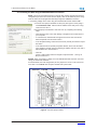
5.00 in
127 mm
12425152
5
CT-
Current Inputs
3141 32
4 3
22 21
2
CW
11
1
WARNING
SCREW FLANGE CABLE HOUSING REQUIRED
TO PREVENT OPENING OF CT SECONDARIES
AND GENERATION OF HAZARDOUS VOLTAGE
Catalog#: PXM8251A1BB
Model#: PXM8200
MAC Address: CM XX:XX:XX:XX:XX:XX CE XX:XX:XX:XX:XX:XX
Serial#: XXXXXX
Style#: 65D8261G006
Current Inputs: 0.05-20A CAT III
Oper Temp: -20 TO 60°C
Voltage Inputs: 0-347 VL:N, 0-600 VL:L CAT III
Freq: 25-66, 350-450 Hz
TA: 2.5
CA: 0.2
MADE IN USA
Date Code: WYYYYMMDD
Rev: XXX
#7054769
U.S. Patents #5890097, #6906655, #6975951, #7050913
Transformer Type
VTR :1
Meter Configuration
CTR :5
Dept. Approval No. AE-1582
Pulse Const./Disk Const.
Meter Tag No.
(8.20)
(6.33)
(6.72)
CW
Voltage Inputs
V4V3
VT-
V2V1
Auxiliary Voltage
VX-
Inputs
V7 V8V6
8.32 in
211.33 mm
8.20 in
208.3 mm
8.88 in
225.6 mm
6.72 in
208.3 mm
6.33 in
160.78 mm
7.36 in
186.9 mm
(8.20)
9.56 in
242.8 mm
Base Meter
0.42 in
10.7 mm
0.34 in
8.6 mm
1.60 in
40.6 mm
R 0.20 in
R 5.2 mm
R 0.11 in
R 2.8 mm
4 X
4 X
Figure 6: Power Xpert 4000/6000/8000 Meter.
Page 18 IB02601007E www.eaton.com
3. Mounting and Wiring

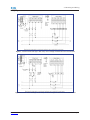
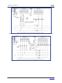
Wiring Diagrams
www.eaton.com IB02601007E Page 19
3. Mounting and Wiring
Figure 7: 3-Phase 3-Wire Delta (Up to 480 Volts). Direct Voltage and External Current Transformers.
Figure 8: 3-Phase 3-Wire Delta (Up to 480 Volts). External Voltage and External Current Transformers.

Page 20 IB02601007E www.eaton.com
3. Mounting and Wiring
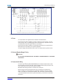
Figure 9: 3-Phase 3-Wire Delta (Up to 480 Volts) 2 CTs. External Voltage and External Current Transformers.
Figure 10: 3-Phase 4-Wire Y (Up to 600 Volts). Direct Voltage and External Current Transformers.
Page is loading ...
Page is loading ...
Page is loading ...
Page is loading ...
Page is loading ...
Page is loading ...
Page is loading ...
Page is loading ...
-
 1
1
-
 2
2
-
 3
3
-
 4
4
-
 5
5
-
 6
6
-
 7
7
-
 8
8
-
 9
9
-
 10
10
-
 11
11
-
 12
12
-
 13
13
-
 14
14
-
 15
15
-
 16
16
-
 17
17
-
 18
18
-
 19
19
-
 20
20
-
 21
21
-
 22
22
-
 23
23
-
 24
24
-
 25
25
-
 26
26
-
 27
27
-
 28
28


Eaton Power Xpert PXM 4000 Quick start guide
- Type
- Quick start guide
- This manual is also suitable for
Ask a question and I''ll find the answer in the document
Finding information in a document is now easier with AI
Related papers
-
Eaton CH 3-4 User manual
-
Eaton Power Xpert PXM 4000 User and Installation Manual
-
-
-
-
-
-
-
-
Other documents
-
Morningstar EMC-1 Quick start guide
-
 T'nB LPXPERTS Datasheet
-
Delta RS485 Operating instructions
-
 T'nB MLDCXSHOTC Datasheet
-
Hubbell Wiring Device-Kellems PD2793 Installation guide
-
Sentinel PXM-2 User manual
-
 T'nB BPNBXPER17 Datasheet
-
 Hoyt KW4000 User manual
-
 Hach sc100TM User manual
-
 T'nB MLDCXSHOTXL Datasheet


