Carrier 33CS Operating instructions
- Category
- Thermostats
- Type
- Operating instructions
This manual is also suitable for

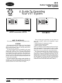
A Guide To Operating
Your VVT System
NOTE TO INSTALLER
This manual should be left with the equipment owner.
GENERAL
This manual will assist you in using your Carrier Comfort
System thermostat. There are 2 basic types of thermostats
that you may encounter. They are called the monitor ther-
mostat and the zone controller.
The monitor thermostat can be identified by the system
switches (FAN, HEAT, COOL) which are located along the
bottom edge of the front cover. The monitor thermostat can
be equipped with or without a timeclock. The timeclock dis-
play is located in the upper right corner of the monitor ther-
mostat. The monitor thermostat display is located in the up-
per left corner. The set point and programming buttons are
located around the display.
The zone controller does not have system switches or a
timeclock. The zone controller display is located in the up-
per left corner of the zone controller. The set point and pro-
gramming buttons are located around the display.
There are three typical operations you may perform on
your VVT (variable volume and temperature) system
thermostat:
• change set points for heating and cooling
• override the unoccupied schedule
• change occupancy schedules
NOTE: Your ability to perform these functions may be lim-
ited by the security access level function which is config-
ured by the installer. If ‘‘access denied’’ is shown on the dis-
play screen, you are not allowed to access that function.
The monitor thermostat and zone controller are part of a
VVT system. The VVT system allows a single-zone heating/
cooling unit to operate as a multiple-zone system. The con-
ditioned space is divided into zones. Each comfort zone is
monitored by a zone controller. The monitor thermostat moni-
tors the operation of its own zone and of each associated
zone controller and determines system operation from in-
formation received from each device that it controls.
Monitor Thermostat With Timeclock
Zone Controller
33CS
Carrier Comfort System
VVTT System
Manufacturer reserves the right to discontinue, or change at any time, specifications or designs without notice and without incurring obligations.
Book 1 4
Tab 11a 13a
PC 111 Catalog No. 809-247 Printed in U.S.A. Form VVT-2SO Pg 1 10-95 Replaces: New

OPERATION
ElectronicTimeclock (Monitor ThermostatOnly)
—
To set the clock, remove the cover of the thermostat. Two
buttons, located under the timeclock, are provided to set the
clock. They are labeled select and adjust. Press the select
button. The minutes setting on the clock will flash. Press the
adjust button until the correct minutes are shown. Press the
select button. The hour setting will flash. Press the adjust
button until the correct hour is shown (including AM and
PM). Press the select button again and the day of the week
will flash. Press the adjust button until the correct day is shown.
Press the select button to return to normal timeclock
operation.
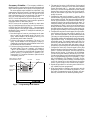
System Switches (Monitor Thermostat Only) —
The monitor thermostat operation mode is controlled by 3
system switches: FAN, HEAT, COOL. See Fig. 1.
The FAN switch can be set to ON or AUTO. When the
FAN switch set to ON, the fan will run continuously. When
the FAN switch is set to AUTO, the fan will only run during
heating and cooling.
The COOL switch can be set to OFF or AUTO. When the
COOL switch set to OFF, the VVTt system will not enter
cooling mode. When the COOL switch is set to AUTO, the
VVT system will enter cooling mode when the zone tem-
perature rises above the cooling set point.
The HEAT switch can be set to OFF or AUTO. When the
HEAT switch set to OFF, the VVT system will not enter heat-
ing mode. When the HEAT switch is set to AUTO, the VVT
system will enter heating mode when the zone temperature
drops below the heating set point.
System Displays — The monitor thermostat and zone
controller have a display window which is used to show sys-
tem information and for programming mode. See Fig. 1.
SET POINT DISPLAY — The heating and cooling set points
are shown in the display window during the normal display
mode. The heating and cooling set points are used to deter-
mine the range of temperatures that are maintained in the
zone.
The cooling set point buttons are located on the left side
of the display screen. The heating set point buttons are lo-
cated on the right side of the display screen.
MODE DISPLAY — When the system fan is energized, the
word FAN appears on the display screen.
When the cooling mode is energized, the word COOL ap-
pears on the display screen. The system fan will also be
energized.
When the heating mode is energized, the word HEAT ap-
pears on the display screen. The system fan will also be en-
ergized, unless it is configured not to run during heating mode.
If the system enters IAQ (indoor air quality) mode, the
word IA9 appears on the display screen.
If the zone controller energizes its supplemental heat source,
the word SUP appears on the display screen.
ALTERNATE DISPLAY— By pressing both cooling or heat-
ing set point buttons simultaneously, the alternate informa-
tion display is activated. The monitor thermostat or zone
controller will display the current zone temperature and then
the time of day. If the Alternate Display function has been
configured to ON, the monitor thermostat or zone controller
will show more detailed zone information. The display will
then return to normal.
Adjustment of Set Points — The cooling and heat-
ing set points are configured through the set point buttons.
The heating set point buttons are located on the right side
of the display screen. Press the upper button to raise the heat-
ing set point temperature. Press the lower button to lower
the heating set point temperature. The heating set point is
limited to a range of 66 to 80 F by the VVT system.
The cooling set point buttons are located on the left side
of the display screen. Press the upper button to raise the cool-
ing set point temperature. Press the lower button to lower
the cooling set point temperature. The cooling set point is
limited to a range of 66 to 80 F by the VVT system.
NOTE: The heating and cooling set point ranges can be con-
figured to smaller ranges.
The heating and cooling set points may be set for the same
temperature, but the thermostat will not allow the cooling
set point to be adjusted lower than the heating set point, or
the heating set point to be adjusted higher than the cooling
set point.
Operating Modes — The monitor thermostat and zone
controller have 3 operating modes: occupied mode, unoc-
cupied mode, and unoccupied override. Occupied mode is
the mode used when the area is normally occupied. Unoc-
cupied mode is used to conserve energy and is used when
the area is normally unoccupied. Unoccupied override is used
to temporarily override unoccupied mode when an area is in
use during the unoccupied schedule time. The user can manu-
ally activate unoccupied override. Set points can be adjusted
during both occupied and unoccupied override modes.
The occupied schedule controls when the zone is in oc-
cupied or unoccupied mode. The schedule can be sent from
a device over the network, or it can be programmed at the
monitor thermostat or zone controller.
UNOCCUPIED OVERRIDE — Unoccupied override is used
to temporarily change the system set points to the occupied
mode set points during unoccupied mode operation. An ex-
ample of unoccupied override would be a worker staying
past 6:00 PM to finish a job when the scheduled unoccupied
time is 6:00 PM.
To override unoccupied mode, press a set point button.
The unoccupied display will be replaced with the occupied
mode display. The monitor thermostat or zone controller will
automatically return to unoccupied mode when the override
timer expires.
Fig. 1 — VVT System Functions and Displays
(Monitor Thermostat Shown)
2

Occupancy Schedule— The occupancy schedule es-
tablishes the time periods when the monitor thermostat and
zone controller operate in the occupied or unoccupied mode.
The unoccupied/occupied schedule has individual 7-day
programming with 8 time periods. Unoccupied/occupied ON/
OFF times are entered on the minute. The start of an ON
time is the beginning of the occupied mode. The start of an
OFF time is the beginning of the unoccupied mode.
NOTE: If an ON time and an OFF time are set for the same
time, the monitor thermostat or zone controller operates in
unoccupied mode for that entire period.
NOTE: Access to the occupancy schedule by certain users
may be limited through the security level access function.
CONFIGURATION OF SCHEDULES — The unoccupied/
occupied program can be directly configured at the monitor
thermostat or zone controller.To configure the schedule, per-
form the following:
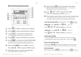
1. Press both upper or lower set point buttons at the same
time to enter into the program mode. The word ‘‘cat-
egory’’and the number 1 will be displayed. See Fig. 2 for
programming mode button functions.
2. Press the left upper set point button. The word ‘‘cat-
egory’’ and the number 2 will be displayed. Category 2
contains the occupied/unoccupied schedules for the moni-
tor thermostat and zone controller.
3. The lower right set point button is the select button. Press
the select button. The word ‘‘category’’ will change to
‘‘option’’ and the number 1 will be displayed. Category
2, options 1 through 8 are the 8 different occupancy time
periods. Option 1 is occupied period 1. Option 2 is oc-
cupied period 2. The options continue to option 8 which
is occupancy period 8.
4. The start time for option 1 will be shown. Each occupied
period (options 2.1 through 2.8) will have three different
screens associated with it — start time, stop time, and
active days. Use the left set point buttons to scroll through
the start time, stop time and active days for each option.
Press the select button (right lower set point button) to
modify the screen.
5. Configure the start time for category 2, option 1. When
the select button is pressed from the start time screen, the
hours number will flash. The hours are modified through
the left set point buttons. The AM/PM modifier will au-
tomatically switch when scrolling through the times. To
change the minutes, press the select button again. The min-
utes numbers will flash. Use the left set point buttons to
modify the minutes. Press select again to save the current
time and return to the options screen, or press escape (up-
per right set point button) to exit without saving changes.
6. Configure the stop time. Press the upper left set point but-
ton to advance to the stop time screen of category 2, op-
tion 1. Press the select button. The hours number will flash.
The hours are modified through the left set point buttons.
TheAM/PM modifier will automatically switch when scroll-
ing through the times. To change the minutes, press the
select button again. The minutes numbers will flash. Use
the left set point buttons to modify the minutes. Press se-
lect again to save the current time and return to the op-
tions screen, or press escape to exit without saving changes.
7. Configure the active days. Press the upper left set point
button to advance to the active days screen of category 2,
option 1. Press the select button. The active days will be
shown and the first day, M (Monday) will be blinking.
Use the left set point buttons to turn the day ON or OFF.
Use the select button to scroll through the possible active
days. The programmable days are: M (Monday), T (Tues-
day), W(Wednesday), TH (Thursday), F (Friday), SA(Sat-
urday), SU (Sunday), and H (Holiday). Press select again
to save the current active days and return to the options
screen, or press escape to exit without saving changes.
8. Repeat this procedure for each time period until the cor-
rect schedule has been programmed.
9. When the schedule is complete, press escape to exit the
programming mode. If no buttons are pressed for 3 min-
utes while in programming mode, the display will auto-
matically revert back to its standard operating mode.
INCREASE
VALUE
DECREASE
VALUE
PRESS BOTH TO ENTER
PROGRAMMING MODE
ESCAPE SELECT
Fig. 2 — Programming Mode Buttons
3

Copyright 1995 Carrier Corporation
Manufacturer reserves the right to discontinue, or change at any time, specifications or designs without notice and without incurring obligations.
Book 1 4
Tab 11a 13a
PC 111 Catalog No. 809-247 Printed in U.S.A. Form VVT-2SO Pg 4 10-95 Replaces: New
-
 1
1
-
 2
2
-
 3
3
-
 4
4


Carrier 33CS Operating instructions
- Category
- Thermostats
- Type
- Operating instructions
- This manual is also suitable for
Ask a question and I''ll find the answer in the document
Finding information in a document is now easier with AI
Related papers
-
Carrier 33CS250-01 User manual
-
-
-
-
-
-
-
-
-
Other documents
-
Bryant P User manual
-
-
-
-
 ActronControls Leasam BM2-7D-4Z Operating instructions
-
 Adp Series 4000 Installation guide
-
Trane IntelliPak SIRG-020 User manual
-
Simplicity 953 User guide
-
Honeywell SuitePRO TB8575A1000 User manual
-
ActronAir C Series Operating instructions

