Page is loading ...

LIT-11616-17-13 5YF-28197-10
YFM50S
SERVICE MANUAL

EBS00001
YFM50S
SERVICE MANUAL
©2003 by Yamaha Motor Corporation, U.S.A.
First Edition, April 2003
All rights reserved.
Any reproduction or unauthorized use
without the written permission of
Yamaha Motor Corporation, U.S.A.
is expressly prohibited.
Printed in U.S.A.
LIT-11616-17-13
EBS00002
NOTICE
This manual was produced by the Yamaha Motor Company primarily for use by Yamaha dealers
and their qualified mechanics. It is not possible to include all the knowledge of a mechanic in one
manual, so it is assumed that anyone who uses this book to perform maintenance and repairs on
Yamaha machine has a basic understanding of the mechanical ideas and the procedures of
machine repair. Repairs attempted by anyone without this knowledge are likely to render the
machine unsafe and unfit for use.
Yamaha Motor Company, Ltd. is continually striving to improve all its models. Modifications and sig-
nificant changes in specifications or procedures will be forwarded to all authorized Yamaha dealers
and will appear in future editions of this manual where applicable.
NOTE:
_
Designs and specifications are subject to change without notice.
EBS00003
IMPORTANT INFORMATION
Particularly important information is distinguished in this manual by the following notations.
The Safety Alert Symbol means ATTENTION! BECOME ALERT! YOUR
SAFETY IS INVOLVED!
Failure to follow WARNING instructions could result in severe injury or death
to the machine operator, a bystander or a person checking or repairing the
machine.
A CAUTION indicates special precautions that must be taken to avoid dam-
age to the machine.
A NOTE provides key information to make procedures easier or clearer.
WARNING
CAUTION:
NOTE:
EBS00004
HOW TO USE THIS MANUAL
MANUAL ORGANIZATION
This manual consists of chapters for the main categories of subjects. (See “symbols”)
1st title
1
: This is the title of the chapter with its symbol in the upper right corner of each page.
2nd title
2
: This title indicates the section of the chapter and only appears on the first page of each
section. It is located in the upper left corner of the page.
3rd title
3
: This title indicates a sub-section that is followed by step-by-step procedures accompa-
nied by corresponding illustrations.
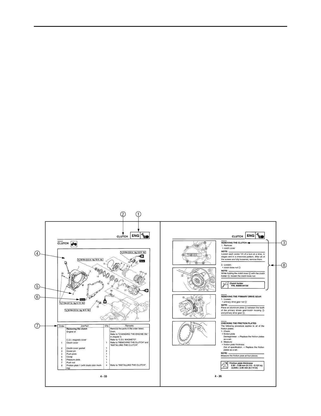
EXPLODED DIAGRAMS
To help identify parts and clarify procedure steps, there are exploded diagrams at the start of each
removal and disassembly section.
1. An easy-to-see exploded diagram
4
is provided for removal and disassembly jobs.
2. Numbers
5
are given in the order of the jobs in the exploded diagram. A number that is enclosed
by a circle indicates a disassembly step.
3. An explanation of jobs and notes is presented in an easy-to-read way by the use of symbol marks
6
. The meanings of the symbol marks are given on the next page.
4. A job instruction chart
7
accompanies the exploded diagram, providing the order of jobs, names
of parts, notes in jobs, etc.
5. For jobs requiring more information, the step-by-step format supplements
8
are given in addition
to the exploded diagram and the job instruction chart.

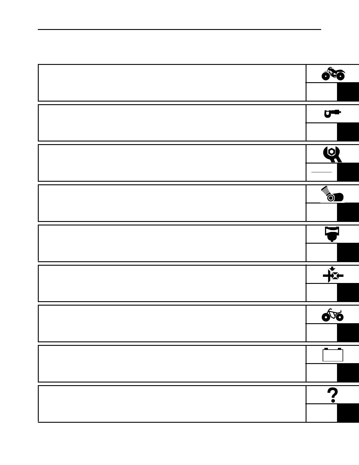
EBS00005
SYMBOLS
The following symbols are not relevant to
every machine.
Symbols
1
to
9
indicate the subject of each
chapter.
1
General information
2
Specifications
3
Periodic checks and adjustments
4
Engine
5
Carburetor
6
Drive train
7
Chassis
8
Electrical
9
Troubleshooting
Symbols
0
to
G
indicate the following.
0
Serviceable with engine mounted
A
Filling fluid
B
Lubricant
C
Special tool
D
Torque
E
Wear limit, clearance
F
Engine speed
G
Electrical data (
Ω
, V, A)
Symbols
H
to
M
in the exploded diagrams
indicate the types of lubricants and lubrication
points.
H
Apply engine oil
I
Apply gear oil
J
Apply molybdenum disulfide oil
K
Apply wheel bearing grease
L
Apply lithium-soap-based grease
M
Apply molybdenum disulfide grease
Symbols
N
to
O
in the exploded diagrams
indicate where to apply a locking agent
N
and
when to install a new part
O
.
N
Apply the locking agent (LOCTITE
®
)
O
Replace
12
34
56
78
90
AB
CD
EFG
HIJ
KLM
NO
GEN
INFO
SPEC
CHK
ADJ
ENG
CARB
DRIV
CHAS
–+
ELEC
TRBL
SHTG
T
R
.
.
E
G
M
B
LS
M
LT
New
EBS00007
TABLE OF CONTENTS
GENERAL INFORMATION
GEN
INFO
1
SPECIFICATIONS
SPEC
2
PERIODIC CHECKS AND
ADJUSTMENTS
CHK
ADJ
3
ENGINE
ENG
4
CARBURETOR
CARB
5
DRIVE TRAIN
DRIV
6
CHASSIS
CHAS
7
ELECTRICAL
ELEC
8
TROUBLESHOOTING
TRBL
SHTG
9
–+

CONTENTS
CHAPTER 1
GENERAL INFORMATION
MACHINE IDENTIFICATION
...........................................................................1-1
VEHICLE IDENTIFICATION NUMBER .....................................................1-1
MODEL LABEL..........................................................................................1-1
IMPORTANT INFORMATION
.........................................................................1-2
PREPARATION FOR REMOVAL AND DISASSEMBLY........................... 1-2
REPLACEMENT PARTS...........................................................................1-2
GASKETS, OIL SEALS AND O-RINGS ....................................................1-2
LOCK WASHERS/PLATES AND COTTER PINS .....................................1-3
BEARINGS AND OIL SEALS ....................................................................1-3
CIRCLIPS ..................................................................................................1-3
CHECKING THE CONNECTIONS............................................................1-4
SPECIAL TOOLS
............................................................................................1-5
CHAPTER 2
SPECIFICATIONS
GENERAL SPECIFICATIONS
........................................................................2-1
ENGINE SPECIFICATIONS
............................................................................2-4
CHASSIS SPECIFICATIONS
........................................................................2-11
ELECTRICAL SPECIFICATIONS
.................................................................2-12
TIGHTENING TORQUES
..............................................................................2-14
ENGINE TIGHTENING TORQUES.........................................................2-14
CHASSIS TIGHTENING TORQUES.......................................................2-15
HOW TO USE THE CONVERSION TABLE
..................................................2-17
GENERAL TIGHTENING TORQUE SPECIFICATIONS
...............................2-17
LUBRICATION POINTS AND LUBRICANT TYPES
....................................2-18
ENGINE...................................................................................................2-18

OIL FLOW DIAGRAMS.................................................................................2-20
CABLE ROUTING .........................................................................................2-22
CHAPTER 3
PERIODIC CHECKS AND ADJUSTMENTS
INTRODUCTION..............................................................................................3-1
PERIODIC MAINTENANCE/LUBRICATION ..................................................3-1
SEAT, FENDERS AND FUEL TANK ..............................................................3-2
SEAT AND FRONT PANEL ......................................................................3-2
FRONT FENDER ......................................................................................3-3
REAR FENDER AND FOOTREST BOARDS ...........................................3-4
FUEL TANK...............................................................................................3-6
ENGINE ...........................................................................................................3-7
ADJUSTING THE TIMING CHAIN TENSIONER ......................................3-7
ADJUSTING THE VALVE CLEARANCE ..................................................3-8
ADJUSTING THE ENGINE IDLING SPEED ........................................... 3-10
ADJUSTING THE THROTTLE LEVER FREE PLAY ..............................3-11
ADJUSTING THE SPEED LIMITER........................................................3-12
CHECKING THE SPARK PLUG .............................................................3-13
CHECKING THE IGNITION TIMING.......................................................3-14
MEASURING THE COMPRESSION PRESSURE..................................3-15
CHECKING THE ENGINE OIL LEVEL....................................................3-17
CHANGING THE ENGINE OIL ...............................................................3-18
CLEANING THE AIR FILTER ELEMENT................................................3-19
CLEANING THE SPARK ARRESTER ....................................................3-20
CHASSIS .......................................................................................................3-22
CHECKING THE FRONT AND REAR BRAKE SHOES..........................3-22
ADJUSTING THE FRONT BRAKE .........................................................3-22
ADJUSTING THE REAR BRAKE............................................................3-23
CHECKING THE FINAL GEAR OIL LEVEL ............................................3-24
CHANGING THE FINAL GEAR OIL........................................................3-24
CHECKING THE SWINGARM DUST BOOT ..........................................3-25
CHECKING THE STEERING SYSTEM ..................................................3-26
ADJUSTING THE TOE-IN.......................................................................3-27
CHECKING THE FRONT AND REAR SHOCK ABSORBERS ...............3-28
CHECKING THE TIRES..........................................................................3-29
CHECKING THE WHEELS .....................................................................3-31
CHECKING AND LUBRICATING THE CABLES ....................................3-32
LUBRICATING THE LEVERS, STEERING SHAFT
AND STEERING KNUCKLES ................................................................3-32

ELECTRICAL SYSTEM.................................................................................3-33
CHECKING AND CHARGING THE BATTERY.......................................3-33
CHECKING THE FUSE...........................................................................3-37
CHAPTER 4
ENGINE
ENGINE ...........................................................................................................4-1
EXHAUST PIPE/MUFFLER, BREATHER HOSE AND LEADS ................4-1
ENGINE MOUNTING BOLTS ...................................................................4-2
REMOVING THE ENGINE ........................................................................4-4
INSTALLING THE ENGINE.......................................................................4-4
CYLINDER HEAD............................................................................................4-5
REMOVING THE CYLINDER HEAD.........................................................4-7
CHECKING THE CAMSHAFT SPROCKET..............................................4-8
CHECKING THE TAPPET COVERS
AND CAMSHAFT SPROCKET COVER...................................................4-8
CHECKING THE TIMING CHAIN GUIDES...............................................4-8
CHECKING THE TIMING CHAIN TENSIONER ASSEMBLY ...................4-8
CHECKING THE CYLINDER HEAD .........................................................4-9
INSTALLING THE CYLINDER HEAD .....................................................4-10
CAMSHAFT, ROCKER ARMS AND VALVES..............................................4-12
REMOVING THE ROCKER ARMS AND CAMSHAFT............................4-14
REMOVING THE VALVES AND VALVE SPRINGS ...............................4-14
CHECKING THE CAMSHAFT.................................................................4-15
CHECKING THE ROCKER ARMS AND ROCKER ARM SHAFTS ........4-15
CHECKING THE VALVES AND VALVE SPRINGS ................................4-17
INSTALLING THE VALVES AND VALVE SPRINGS ..............................4-21
INSTALLING THE CAMSHAFT AND ROCKER ARMS ..........................4-22
CYLINDER AND PISTON..............................................................................4-23
REMOVING THE PISTON ......................................................................4-24
CHECKING THE CYLINDER AND PISTON ...........................................4-24
CHECKING THE PISTON RINGS...........................................................4-26
CHECKING THE PISTON PIN ................................................................4-27
INSTALLING THE PISTON .....................................................................4-28
INSTALLING THE CYLINDER ................................................................4-29
C.D.I. MAGNETO...........................................................................................4-30
REMOVING THE C.D.I. MAGNETO ROTOR .........................................4-31
CHECKING THE PICKUP COIL/STATOR ASSEMBLY..........................4-31
INSTALLING THE C.D.I. MAGNETO ROTOR ........................................4-32
INSTALLING THE SHIFT LEVER ........................................................... 4-32

CLUTCH ........................................................................................................4-33
REMOVING THE CLUTCH .....................................................................4-35
REMOVING THE PRIMARY DRIVE GEAR ............................................4-35
CHECKING THE FRICTION PLATES.....................................................4-35
CHECKING THE CLUTCH PLATES .......................................................4-36
CHECKING THE CLUTCH SPRINGS.....................................................4-36
CHECKING THE CLUTCH HOUSING ....................................................4-36
CHECKING THE CLUTCH BOSS...........................................................4-37
CHECKING THE PRESSURE PLATE ....................................................4-37
CHECKING THE CLUTCH BALLS..........................................................4-37
CHECKING THE PRIMARY DRIVE GEARS ..........................................4-37
INSTALLING THE PRIMARY DRIVE GEAR...........................................4-38
INSTALLING THE CLUTCH....................................................................4-38
STARTER CLUTCH AND OIL PUMP ...........................................................4-42
CHECKING THE STARTER CLUTCH ....................................................4-44
CHECKING THE OIL PUMP ...................................................................4-45
SHIFT SHAFT................................................................................................4-47
CHECKING THE SHIFT SHAFT .............................................................4-48
CHECKING THE STOPPER LEVER ......................................................4-48
INSTALLING THE STOPPER LEVER ....................................................4-48
INSTALLING THE SHIFT SHAFT ...........................................................4-48
CRANKCASE ................................................................................................4-49
CRANKCASE BEARINGS.......................................................................4-50
SEPARATING THE CRANKCASE..........................................................4-51
CHECKING THE TIMING CHAIN............................................................4-51
CHECKING THE BEARINGS AND OIL SEALS......................................4-52
CHECKING THE CRANKCASE ..............................................................4-52
INSTALLING THE BEARINGS................................................................4-52
ASSEMBLING THE CRANKCASE..........................................................4-53
CRANKSHAFT ..............................................................................................4-54
CHECKING THE CRANKSHAFT ............................................................4-55
INSTALLING THE CRANKSHAFT ..........................................................4-55
TRANSMISSION............................................................................................4-56
REMOVING THE TRANSMISSION ........................................................4-57
CHECKING THE SHIFT FORK ...............................................................4-57
CHECKING THE SHIFT DRUM ..............................................................4-58
CHECKING THE TRANSMISSION .........................................................4-58
INSTALLING THE TRANSMISSION .......................................................4-59
MIDDLE GEAR ..............................................................................................4-60
REMOVING THE MIDDLE DRIVEN SHAFT...........................................4-61
CHECKING THE PINION GEARS ..........................................................4-62
SELECTING MIDDLE DRIVEN GEAR SHIMS .......................................4-63
INSTALLING THE MIDDLE DRIVEN SHAFT .........................................4-64
MEASURING THE MIDDLE GEAR BACKLASH.....................................4-66

CHAPTER 5
CARBURETOR
CARBURETOR
................................................................................................5-1
DISASSEMBLING THE CARBURETOR...................................................5-4
CHECKING THE CARBURETOR .............................................................5-4
ASSEMBLING THE CARBURETOR.........................................................5-6
INSTALLING THE CARBURETOR ...........................................................5-6
MEASURING AND ADJUSTING THE FUEL LEVEL ................................5-7
CHAPTER 6
DRIVE TRAIN
TROUBLESHOOTING
.....................................................................................6-1
CHECKING NOISES .................................................................................6-2
TROUBLESHOOTING CHART .................................................................6-4
REAR AXLE/FINAL DRIVE ASSEMBLY AND DRIVE SHAFT
......................6-5
REAR AXLE/FINAL DRIVE ASSEMBLY...................................................6-7
REMOVING THE NUTS ............................................................................6-8
REMOVING THE REAR AXLE/FINAL DRIVE ASSEMBLY ......................6-8
DISASSEMBLING THE REAR AXLE HOUSING ......................................6-9
DISASSEMBLING THE FINAL GEAR CASE............................................6-9
CHECKING THE REAR AXLE ................................................................6-10
CHECKING THE DRIVE SHAFT.............................................................6-10
CHECKING THE REAR AXLE HOUSING
AND FINAL DRIVE ASSEMBLY ............................................................6-10
ASSEMBLING THE FINAL GEAR CASE................................................6-11
ASSEMBLING THE REAR AXLE HOUSING ..........................................6-11
INSTALLING THE REAR AXLE/FINAL DRIVE ASSEMBLY...................6-12
INSTALLING THE NUTS.........................................................................6-13
CHAPTER 7
CHASSIS
FRONT AND REAR WHEELS
........................................................................7-1
FRONT WHEELS ......................................................................................7-1
REAR WHEELS ........................................................................................7-2
CHECKING THE WHEELS .......................................................................7-3
CHECKING THE FRONT WHEEL HUBS .................................................7-3
CHECKING THE REAR WHEEL HUBS....................................................7-4
INSTALLING THE WHEEL HUBS.............................................................7-4
INSTALLING THE WHEELS .....................................................................7-5

FRONT AND REAR BRAKES.........................................................................7-6
FRONT BRAKE .........................................................................................7-6
REAR BRAKE ...........................................................................................7-7
REMOVING THE BRAKES ....................................................................... 7-9
CHECKING THE BRAKE SHOE PLATES ................................................7-9
CHECKING THE BRAKE SHOES.............................................................7-9
CHECKING THE BRAKE DRUMS ..........................................................7-10
INSTALLING THE FRONT BRAKES ......................................................7-11
INSTALLING THE REAR BRAKE ...........................................................7-12
STEERING SYSTEM.....................................................................................7-14
HANDLEBAR...........................................................................................7-14
REMOVING THE HANDLEBAR GRIPS..................................................7-16
REMOVING THE REAR BRAKE SWITCH .............................................7-16
CHECKING THE HANDLEBAR ..............................................................7-16
INSTALLING THE HANDLEBAR ............................................................7-17
INSTALLING THE HANDLEBAR GRIPS ................................................7-17
INSTALLING THE REAR BRAKE LEVER ..............................................7-18
INSTALLING THE FRONT BRAKE LEVER ASSEMBLY........................7-18
STEERING STEM ...................................................................................7-19
REMOVING THE STEERING STEM ......................................................7-20
CHECKING THE STEERING STEM .......................................................7-20
INSTALLING THE STEERING STEM .....................................................7-20
INSTALLING THE LOCK WASHER........................................................7-20
TIE-RODS AND STEERING KNUCKLES ...............................................7-21
REMOVING THE TIE-RODS...................................................................7-22
CHECKING THE TIE-RODS ...................................................................7-22
CHECKING THE STEERING KNUCKLES..............................................7-22
INSTALLING THE TIE-RODS .................................................................7-23
FRONT SHOCK ABSORBER ASSEMBLIES AND FRONT SWINGARM ... 7-24
REMOVING THE FRONT SWINGARM ..................................................7-25
CHECKING THE FRONT SWINGARM...................................................7-25
CHECKING THE FRONT SHOCK ABSORBER ASSEMBLIES .............7-25
REAR SHOCK ABSORBER AND REAR SWINGARM ................................7-26
REMOVING THE REAR SWINGARM.....................................................7-27
CHECKING THE REAR SHOCK ABSORBER........................................7-27
CHECKING THE REAR SWINGARM .....................................................7-28
CHECKING THE DUST BOOT ...............................................................7-28
INSTALLING THE LOCK WASHER........................................................7-28

CHAPTER 8
ELECTRICAL
ELECTRICAL COMPONENTS
........................................................................8-1
CHECKING SWITCH CONTINUITY
................................................................8-2
CHECKING THE SWITCHES
..........................................................................8-3
CHECKING THE BULBS AND BULB SOCKETS
..........................................8-4
TYPES OF BULBS ....................................................................................8-4
CHECKING THE CONDITION OF THE BULBS .......................................8-4
CHECKING THE CONDITION OF THE BULB SOCKETS .......................8-6
IGNITION SYSTEM
.........................................................................................8-7
CIRCUIT DIAGRAM ..................................................................................8-7
TROUBLESHOOTING ..............................................................................8-8
ELECTRIC STARTING SYSTEM
..................................................................8-12
CIRCUIT DIAGRAM ................................................................................8-12
STARTING CIRCUIT OPERATION.........................................................8-13
TROUBLESHOOTING ............................................................................8-14
STARTER MOTOR
........................................................................................8-18
CHECKING THE STARTER MOTOR .....................................................8-19
ASSEMBLING THE STARTER MOTOR.................................................8-20
CHARGING SYSTEM
....................................................................................8-21
CIRCUIT DIAGRAM ................................................................................8-21
TROUBLESHOOTING ............................................................................8-22
SIGNAL SYSTEM
..........................................................................................8-24
CIRCUIT DIAGRAM ................................................................................8-24
TROUBLESHOOTING ............................................................................8-25
CHECKING THE SIGNALING SYSTEM .................................................8-26
CHAPTER 9
TROUBLESHOOTING
STARTING FAILURE/HARD STARTING
.......................................................9-1
FUEL SYSTEM..........................................................................................9-1
ELECTRICAL SYSTEM.............................................................................9-1
COMPRESSION SYSTEM........................................................................9-2

POOR IDLE SPEED PERFORMANCE ...........................................................9-2
POOR IDLE SPEED PERFORMANCE.....................................................9-2
POOR MEDIUM AND HIGH-SPEED PERFORMANCE..................................9-2
POOR MEDIUM AND HIGH-SPEED PERFORMANCE ...........................9-2
FAULTY DRIVE TRAIN...................................................................................9-3
FAULTY GEAR SHIFTING..............................................................................9-4
HARD SHIFTING.......................................................................................9-4
SHIFT LEVER DOES NOT MOVE ............................................................ 9-4
JUMPS OUT GEAR...................................................................................9-4
CLUTCH SLIPPING/DRAGGING....................................................................9-4
CLUTCH SLIPPING ..................................................................................9-4
CLUTCH DRAGGING ...............................................................................9-4
OVERHEATING...............................................................................................9-4
OVERHEATING ........................................................................................9-4
FAULTY BRAKE .............................................................................................9-5
POOR BRAKING EFFECT........................................................................9-5
SHOCK ABSORBER MALFUNCTION ...........................................................9-5
MALFUNCTION.........................................................................................9-5
UNSTABLE HANDLING..................................................................................9-5
UNSTABLE HANDLING ............................................................................9-5
1 - 1
GEN
INFO
EBS00009
GENERAL INFORMATION
MACHINE IDENTIFICATION
EBS00010
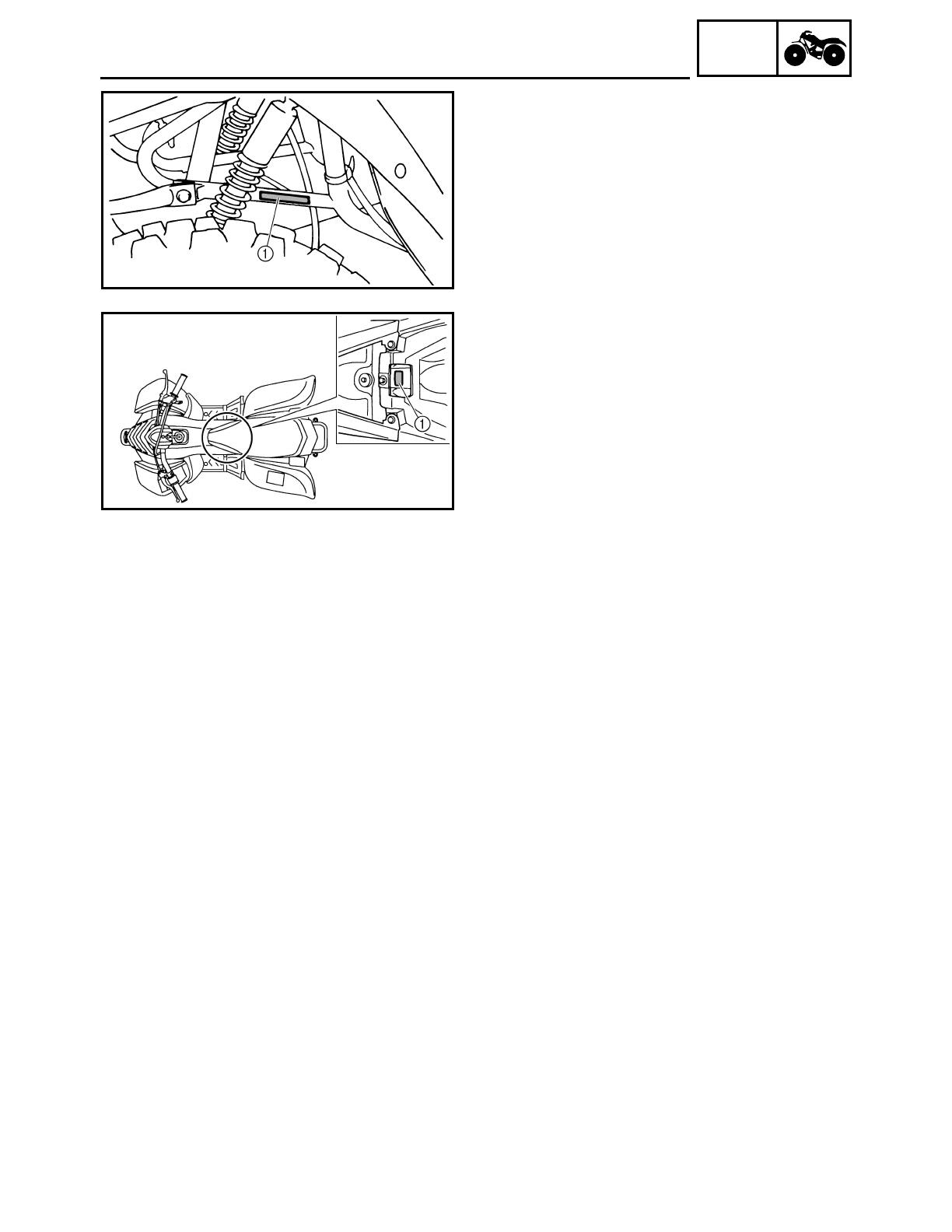
VEHICLE IDENTIFICATION NUMBER
The vehicle identification number
1
is
stamped into the left side of the frame.
EBS00011
MODEL LABEL
The model label
1
is affixed to the frame. This
information will be needed to order spare
parts.
MACHINE IDENTIFICATION
1 - 2
GEN
INFO
IMPORTANT INFORMATION
EBS00013
IMPORTANT INFORMATION
PREPARATION FOR REMOVAL AND
DISASSEMBLY
1. Before removal and disassembly remove all
dirt, mud, dust and foreign material.
2. Use only the proper tools and cleaning
equipment.
Refer to “SPECIAL TOOLS”.
3. When disassembling always keep mated
parts together. This includes gears, cylin-
ders, pistons and other parts that have been
“mated” through normal wear. Mated parts
must always be reused or replaced as an
assembly.
4. During disassembly, clean all of the parts
and place them in trays in the order of dis-
assembly. This will speed up assembly and
allow for the correct installation of all parts.
5. Keep all parts away from any source of fire.
EBS00014
REPLACEMENT PARTS
1. Use only genuine Yamaha parts for all
replacements. Use oil and grease recom-
mended by Yamaha for all lubrication jobs.
Other brands may be similar in function and
appearance, but inferior in quality.
EBS00015
GASKETS, OIL SEALS AND O-RINGS
1. When overhauling the engine, replace all
gaskets, seals and O-rings. All gasket sur-
faces, oil seal lips and O-rings must be
cleaned.
2. During reassembly properly oil all mating
parts and bearings, and lubricate the oil
seal lips with grease.
1
1 - 3
GEN
INFO
IMPORTANT INFORMATION
EBS00016
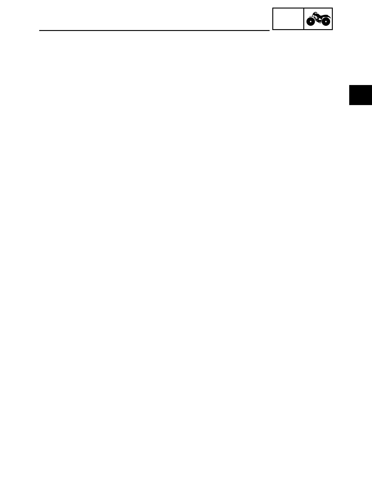
LOCK WASHERS/PLATES AND COTTER
PINS
After removal, replace all lock washers/plates
1
and cotter pins. After the bolt or nut has
been tightened to specification, bend the lock
tabs along a flat of the bolt or nut.
EBS00017
BEARINGS AND OIL SEALS
Install bearings and oil seals so that the manu-
facturer’s marks or numbers are visible. When
installing oil seals, lubricate the oil seal lips
with a light coat of lithium-soap-based grease.
Oil bearings liberally when installing, if appro-
priate.
1
Oil seal
CAUTION:
_
Do not spin the bearing with compressed
air because this will damage the bearing
surfaces.
1
Bearing
EBS00018
CIRCLIPS
Before reassembly, check all circlips carefully
and replace damaged or distorted circlips.
Always replace piston pin clips after one use.
When installing a circlip
1
, make sure the
sharp-edged corner
2
is positioned opposite
the thrust
3
that the circlip receives.
4
Shaft
1 - 4
GEN
INFO
IMPORTANT INFORMATION
EBS00019
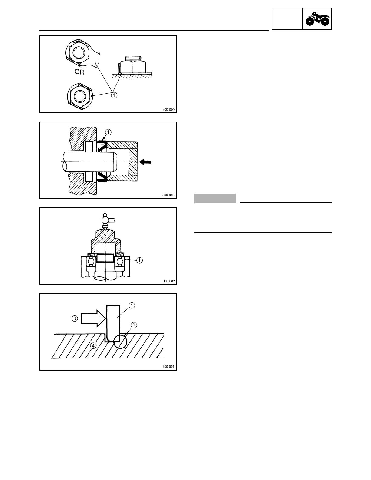
CHECKING THE CONNECTIONS
Check the leads, couplers, and connectors for
stains, rust, moisture, etc.
1. Disconnect:
• lead
• coupler
• connector
2. Check:
• lead
• coupler
• connector
Moisture
→
Dry with an air blower.
Rust/stains
→
Connect and disconnect sev-
eral times.
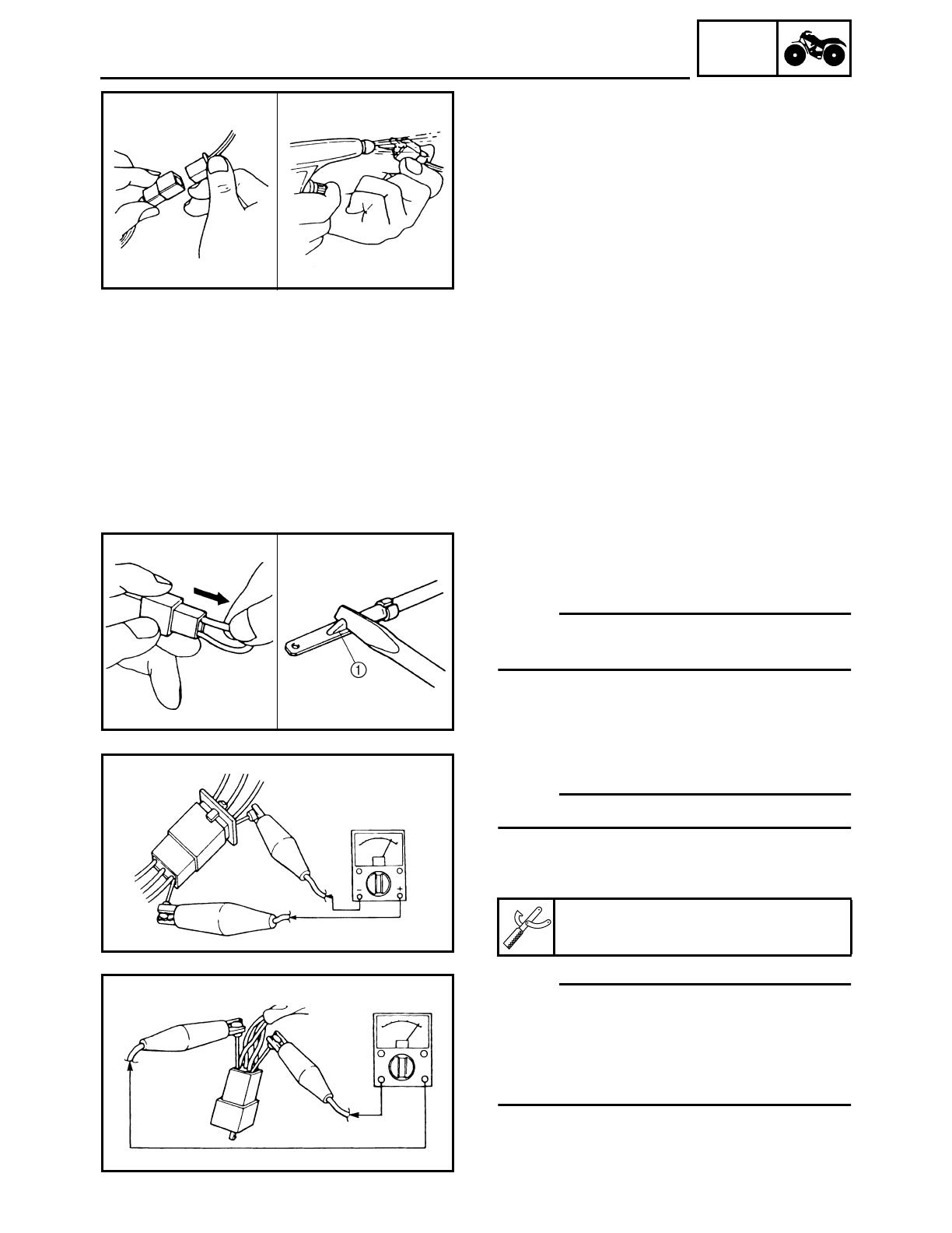
3. Check:
• all connections
Loose connection
→
Connect properly.
NOTE:
_
If the pin
1
on the terminal is flattened, bend it
up.
4. Connect:
• lead
• coupler
• connector
NOTE:
_
Make sure all connections are tight.
5. Check:
• continuity (with the pocket tester)
NOTE:
_
• If there is no continuity, clean the terminals.
• When checking the wire harness, perform
steps (1) to (3).
• As a quick remedy, use a contact revitalizer
available at most part stores.
Pocket tester
P/N. YU-03112-C, 90890-03112
1 - 5
GEN
INFO
SPECIAL TOOLS
EBS00021
SPECIAL TOOLS
The following special tools are necessary for complete and accurate tune-up and assembly. Use
only the appropriate special tools; this will help prevent damage caused by the use of inappropriate
tools or improvised techniques. Special tools may differ by shape and part number from country to
country. In such a case, two types are provided.
When placing an order, refer to the list provided below to avoid any mistakes.
For US and CDN
P/N. YM-, YU-, YS-, YK-, ACC-
Except for US and CDN
P/N. 90890-
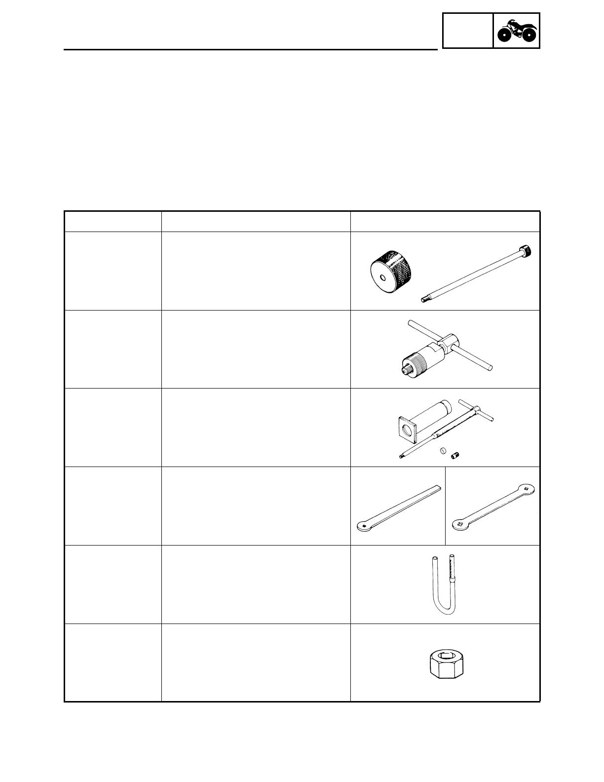
Tool No. Tool name/Function Illustration
Bolt
90890-01085
Weight
90890-01084
Set
YU-01083-A
Slide hammer bolt (M8)/weight/set
These tools are used to remove the rocker
arm shaft.
90890-01189
YM-01189
Flywheel puller
This tool is needed to remove the rotor.
90890-01304
YU-01304
Piston pin puller set
This tool is used to remove the piston pin.
90890-01311
YM-08035
Tappet adjusting tool (3 mm)
This tool is necessary for adjusting the
valve clearance.
90890-01312
YM-01312-A
Fuel level gauge
This gauge is used to measure the fuel
level in the float chamber.
90890-01388
Damper rod holder (27 mm)
This tool is needed to loosen and tighten
the middle driven pinion gear bearing
retainer.

1 - 6
GEN
INFO
SPECIAL TOOLS
90890-01422
YM-37132
Axle nut wrench (36 mm)
This tool is needed to loosen or tighten the
rear axle nut.
90890-01430
YM-38404
Ring nut wrench
This tool is needed to loosen and tighten
the final gear case bearing retainer.
90890-01467
YM-01467
Gear lash measurement tool
This tool is used to measure the middle
gear backlash.
90890-01701
YS-01880-A
Sheave holder
This tool is needed to hold the rotor when
removing or installing the rotor nut.
Gauge
90890-03081
YU-33223
Adapter
90890-04082
Compression gauge
Adapter
These tools are needed to measure
engine compression.
90890-03112
YU-03112-C
Pocket tester
This instrument is needed for checking the
electrical system.
90890-03113
Engine tachometer
This tool is needed for observing engine
rpm.
90890-03141
YM-33277-A
Timing light
This tool is necessary for checking ignition
timing.
Tool No. Tool name/Function Illustration
/