Page is loading ...

Series 93
1/16 DIN Microprocessor-Based
Auto-tuning Control
0600-0001-0000 Rev E Made in the U.S.A.
October 2003 $10.00
User’s Manual
1241 Bundy Blvd., P.O. Box 5580, Winona, Minnesota USA 55987-5580
Phone: (507) 454-5300, Fax: (507) 452-4507 http://www.watlow.com
Registered Company
Winona, Minnesota USA
ISO 9001
TOTAL
3 Year Warranty
CUSTOMER
SATISFACTION
User Levels:
• New User . . . . . . . . . . . . . . . . . . . . . . . . . . .go to page 1.1
• Experienced User . . . . . . . . . . . . . . . . . . . . .go to page 2.1
• Expert user . . . . . . . . . . . . . . . . . . . . . . . . . .go to page 2.1
Installers:
• Installation . . . . . . . . . . . . . . . . . . . . . . . . . .go to page 2.1
• Wiring . . . . . . . . . . . . . . . . . . . . . . . . . . . . . .go to page 2.3

Safety Information
We use note, caution and warning symbols throughout this book to draw your attention to
important operational and safety information.
A “NOTE” marks a short message to alert you to an important detail.
A “CAUTION” safety alert appears with information that is important for protecting your
equipment and performance. Be especially careful to read and follow all cautions that apply to
your application.
A “WARNING” safety alert appears with information that is important for protecting you, oth-
ers and equipment from damage. Pay very close attention to all warnings that apply to your
application.
The safety alert symbol, ç (an exclamation point in a triangle) precedes a general CAUTION
or WARNING statement.
The electrical hazard symbol, Ó (a lightning bolt in a triangle) precedes an electric shock haz-
ard CAUTION or WARNING safety statement.
Technical Assistance
If you encounter a problem with your Watlow controller, review your configuration informa-
tion to verify that your selections are consistent with your application: inputs, outputs,
alarms, limits, etc. If the problem persists, you can get technical assistance from your local
Watlow representative (see back cover), by e-mailing your questions to wintechsupport@wat
-
low.com
or by dialing +1 (507) 494-5656 between 7 a.m. and 5 p.m., Central Standard Time
(CST). Ask for for an Applications Engineer. Please have the following information available
when calling:
• Complete model number • All configuration information
• User’s Manual • Factory Page
Warranty
The Series 93 is manufactured by ISO 9001-registered processes and is backed by a three-year
warranty.
Return Material Authorization (RMA)
1. Call Watlow Customer Service, (507) 454-5300, for a Return Material Authorization
(RMA) number before returning any item for repair. If you do not know why the product
failed, contact an Application Engineer or Product Manager. All RMA’s require:
• Ship to address • Bill to address
• Contact name • Phone number
• Method of return shipment • Your P.O. number
• Detailed description of the problem • Any special instructions
• Name and phone number of person returning the product.
2. Prior approval and an RMA number from the Customer Service Department is required
when returning any product for credit, repair or evaluation. Make sure the RMA number is on
the outside of the carton and on all paperwork returned. Ship on a Freight Prepaid basis.
3. After we receive your return, we will examine it and try to verify the reason for returning it.
4. In cases of manufacturing defect, we will enter a repair order, replacement order or issue
credit for material returned. In cases of customer mis-use, we will provide repair costs and
request a purchase order to proceed with the repair work.
5. To return products that are not defective, goods must be be in new condition, in the origi-
nal boxes and they must be returned within 120 days of receipt. A 20 percent restocking
charge is applied for all returned stock controls and accessories.
6. If the unit is unrepairable, you will receive a letter of explanation. and be given the option
to have the unit returned to you at your expense or to have us scrap the unit.
7. Watlow reserves the right to charge for no trouble found (NTF) returns.
The Series 93 User’s Manual is copyrighted by Watlow Winona, Inc., © October 2003 with all
rights reserved. (2405)
ç
CAUTION or
WARNING
Ó
Electrical
Shock Hazard
CAUTION or WARNING

Watlow Series 93 Table of Contents ■ i
Chapter 1: Overview ......................................................... 1.1
General Description ................................................ 1.1
Chapter 2: Install And Wire The Series 93 .................... 2.1
Panel Cutout ............................................................2.1
Dimensions ..............................................................2.1
Installation Procedure ..............................................2.1
Wiring the Series 93 ................................................2.3
Power Wiring............................................................2.3
Sensor Installation Guidelines .................................2.4
Input Wiring .............................................................2.4
Output 1 Wiring ...................................................... 2.6
Output 2 Wiring ...................................................... 2.8
System Wiring Example .......................................... 2.9
Chapter 3: How To Use The Keys And Displays ............ 3.1
Keys, Displays and Indicator Lights ........................ 3.1
Chapter 4: How To Set Up The Series 93 ...................... 4.1
Setting the Input Type DIP Switch .......................... 4.1
Entering Setup Menu .............................................. 4.2
Setup Parameters ................................................... 4.3
Setup Menu Table ................................................... 4.5
Operation Parameters ............................................. 4.6
Operation Menu Table ............................................. 4.7
Chapter 5: How To Tune And Operate ........................... 5.1
Autotuning .............................................................. 5.1
Manual Tuning ........................................................ 5.2
Manual and Automatic Operation ............................ 5.3
Setting the Set Point.................................................5.3
Using Alarms .......................................................... 5.4
Error Code Messages ............................................. 5.5
Error Code Actions ...................................................5.6
Appendix ........................................................................ A.1
Noise and Installation Guidelines .............................A.1
Noise Sources .........................................................A.1
Decreasing Noise Sensitivity ...................................A.1
Eliminating Noise .................................................... A.2
Entering the Calibration Menu .................................A.3
Restoring Factory Calibration ................................. A.4
Calibration Menu .................................................... A.4
Calibration Procedures ........................................... A.5
Glossary ................................................................. A.9
Specifications ....................................................... A.12
Model Number Information .................................. A.13
Index .................................................................... A.14
Declaration of Conformity.......................................A.15
Quick Reference ................................................... A.17
Figures and Tables
Figures ...................................................... Page
Series 93 Input and Output Overview ..............................1.1
Series 93 Multiple Panel Cutout Dimensions .................2.1a
Series 93 Dimensions ....................................................2.1b
Mounting, Case Side View ............................................. 2.2a
Mounting Collar..............................................................2.2b
Case Rear View and IP65 (NEMA 4X) Seal Example ..... 2.2c
Power Wiring .................................................................. 2.3
Thermocouple Sensor Input Wiring .............................. 2.4a
2- or 3-wire RTD Sensor Input Wiring .......................... 2.4b
0-5VÎ (dc) Process Sensor Input Wiring ..................... 2.5a
4-20mA Process Sensor Input Wiring ...........................2.5b
Output 1 Mechanical Relay Wiring ................................ 2.6a
Output 1 Solid-state Relay w/o Suppression Wiring ..... 2.6b
Switched DC Output 1 Wiring ....................................... 2.7a
4-20mA Process Wiring ............................................... 2.7b
Output 2 Mechanical Relay Wiring ................................ 2.8a
Output 2 Solid-state Relay w/o Suppression Wiring .....2.8b
Switched DC Output 2 Wiring ....................................... 2.8c
System Wiring Example .................................................. 2.9
Wiring Notes...................................................................2.10
Series 93 Keys and Displays ........................................... 3.1
DIP Switch Location and Orientation ............................ 4.1a
Input DIP Switches.........................................................4.1b
Entering the Setup Menu .............................................. 4.2a
The Setup Menu ........................................................... 4.2b
The Operation Menu ....................................................... 4.6
Autotuning at a 200°F Set Point ..................................... 5.1
Clearing an Alarm ........................................................... 5.4
Error Code Message ....................................................... 5.5
Entering the Calibration Menu ........................................ A.3
Calibration Menu ............................................................ A.4
Tables ...................................................... Page
Input Ranges ................................................................. 4.5a
Setup Menu Prompts and Descriptions ......................... 4.5b
Operation Menu Prompts and Descriptions..................... 4.7
Quick Reference Sheet .........................................A.17-A.18
TC
Table of Contents

ii ■ Table of Contents Watlow Series 93
Notes

Watlow Series 93 Overview ■ 1.1
Overview
General Description
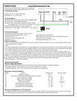
Welcome to the Watlow Series 93, a 1/16 DIN microprocessor-based tempera-
ture controller. The 93 has a single input which accepts type J, K, T, N or S
thermocouple, RTD or process input.
With dual output, the primary output can be heating or cooling while the
secondary output can be a control output opposite the primary output (heat or
cool), alarm or none. Both outputs can be selected as either PID or on-off.
PID settings include proportional band, reset/integral, and rate/derivative.
Setting the proportional band to zero makes the Series 93 a simple on-off
controller with switching differential selectable under the [`HSC] parameter.
Special 93 features include the optional NEMA 4X rating, optional CE
compliance, dual four-digit displays in either red or green, optional low-voltage
power supply, autotuning for both heat and cool outputs, ramp to set point for
gradual warm-up of your thermal system, and automatic/manual capability
with bumpless transfer.
Operator-friendly features include automatic LED indicators to aid in
monitoring and setup, as well as a calibration offset at the front panel. The
Watlow Series 93 automatically stores all information in a non-volatile
memory.
Single Input -
Type J, K, T, N or S
Thermocouple,
RTD or Process
Output 1 -
Heat or Cool
Dual Control Output-
PID or on-off, User Selectable
Output 2 -
Heat, Cool, Alarm
or None
Overview of the Series 93
93
1
Figure 1.1 -
Series 93 Input and
Output Overview.

Overview
1.2 ■ Overview Watlow Series 93
Notes

Panel Cutout
Your Panel
Thickness
1.5 to 9.7 mm
(0.06 to 0.38 in.)
44.96 mm to 45.47 mm
(1.77 to 1.79 in.)
44.96
to 45.47 mm
(1.77 to 1.79 in.)
9.65 mm
(0.38 in.)
Minimum
20 mm
(0.85 in.)
93
53 mm
(2.1 in.)
53 mm
(2.1 in.)
Watlow Series 93 Install and Wire ■ 2.1
Install and Wire
Figure 2.1a -
Series 93 Multiple
Panel Cutout
Dimensions.
Installation procedure
Bold print denotes requirement for IP65 (NEMA 4X) seal. Follow this
procedure to mount the Watlow Series 93 temperature controller:
1. Make a panel cutout using the dimensions in Figure 1a.
2. If your controller model number begins with 93B, make sure the
rounded side of the external case gasket is facing the panel sur-
face. Check to see that the gasket is not twisted, and is seated within the
case bezel flush with the panel. Place the case in the cutout. Make sure
the gasket is between the panel cutout and the case bezel.
NOTE:
Measurements
between panel
cutouts are the mini-
mum recommended.
Figure 2.1b-
Series 93
Dimensions.
10 mm
(0.40 in.)
31 mm
(1.21 in.)
104 mm
(4.1 in.)
119 mm
(4.7 in.)
45 mm
(1.76 in.)
NOTE:
For rapid mounting,
use Greenlee 1/16
DIN punch, die, draw
stud, part number
60287.
2
Install and Wire the Series 93

2.2 ■ Install and Wire Watlow Series 93
Install and Wire
Figure 2.2a -
Mounting Case Side
View.
Figure 2.2b -
Mounting Collar
Cross Section with
offset teeth.
Figure 2.2c -
Case Rear View and
IP65 (NEMA 4X) Seal
Example.
0 to 0.483 mm space
(0 to 0.019 in.)
Bezel
Panel
External Gasket
Mounting Collar
Ridges
Teeth
Tabs
4. Insert the controller chassis into its case and press the bezel to seat it. Make
sure the inside gasket is also seated properly and not twisted. The hardware
installation is complete. Proceed to the wiring section from here.
Removing the Series 93 Controller
When removing the mounting collar, we suggest using a thin tool such as a
putty knife or screwdriver to pry gently under each of the six tabs to disen-
gage the teeth. Then rock the collar back and forth until it can be easily
pulled off the case.
3. While pressing the front of the case firmly against the panel, slide the
mounting collar over the back of the controller. The tabs on the collar must
line up with the mounting ridges on the case for secure installation. See
Figure 2a. Slide the collar firmly against the back of the panel getting it as
tight as possible.
To ensure a tight seal, use your thumb to lock the tabs into place while press-
ing the case from side to side. Don’t be afraid to apply enough pressure to
install the controller. The tabs on each side of the collar have teeth which
latch into the ridges. See Figure 2b. Each tooth is staggered at a different
height, so only one of the tabs on each side are ever locked into the ridges at
any time.
Confirm that the tabs on one side of the collar correspond with those on the
opposite side. Make sure the two corresponding tabs are the only ones locked
in the ridges at the same time.
If the corresponding tabs are not supporting the case at the same
time, and the space between the panel and the case bezel is greater
than .019 inch, you will will not have a IP65 (NEMA 4X) seal. This
applies to units with models designated 93B. However, all units should
be mounted in this fashion to guarantee integrity of the mounting system.
IP65 (NEMA 4X) Seal Example.
Make sure that the two corresponding tabs
are locked in the ridges at the same time
.
ç
CAUTION: Follow the
installation procedure
exactly to guarantee a
proper IP65 (NEMA
4X) seal. Make sure
the gasket between
the panel and the rim
of the case is not
twisted and is seated
properly. Failure to
do so could result in
damage to equip-
ment.

Wiring the Series 93
The Series 93 wiring is illustrated by model number option.
Check the unit sticker on the controller and compare your model
number to those shown here and also the model number break-
down in the Appendix of this manual.
All outputs are referenced to a de-energized state. The final
wiring figure is a typical system example.
When you apply power without sensor inputs on the terminal
strip, the Series 93 displays [----] in the upper display, and
[```0] in the lower display, except for 0-5VÎ (dc) or 4-20mA
process input units. Press the ˆInfinity key twice, and [ER`7]
is displayed for one second. This error indicates an open sensor
or an analog-to-digital error. All wiring and fusing must con-
form to the National Electric Code and to any locally applicable
codes as well.
Power Wiring
High Voltage
100 to 240Å (ac), nominal (85 to 264 actual) 93_ _-1_ _ 0 - 00_ _
Low Voltage
12 to 24V‡ (ac/dc) 93_ _- 1_ _ 1 - 00_ _
Figure 2.3 – Power Wiring.
L1 L2
11 12
93
Watlow Series 93 Install and Wire ■ 2.3
Install and Wire
∫
WARNING: To avoid
electric shock, use
National Electric
Code (NEC) safety
practices when
wiring and connect-
ing this unit to a
power source and to
electrical sensors or
peripheral devices.
Failure to do so could
result in injury or
death.
NOTE:
Taking the unit out of
the case is not a nor-
mal operating condi-
tion and should only
be done by a quali-
fied maintenance
installation techni-
cian. Power to the
case should be dis-
connected before
removing or
installing the con-
troller into its case.
∫
WARNING: The case
terminals may still
carry live voltage
when the unit is
removed.
∫
WARNING:
Irreversible damage
will occur if high
voltage is applied to
the low voltage unit.
NOTE: Optional protective rear terminal
cover, 0822-0426-P001, is available.
Contact Watlow customer service or your
local Watlow sales representative.

Sensor Installation Guidelines
We suggest you mount the sensor at a location in your process or system where
it reads an average temperature. Put the sensor as near as possible to the mate-
rial or space you want to control. Air flow past this sensor should be moderate.
The sensor should be thermally insulated from the sensor mounting.
See Chapter 4 for more information on DIP switch location and orientation.
Input Wiring
Figure 2.4a – Thermocouple
Extension wire for thermocouples must be of the same alloy as the thermo-
couple itself to limit errors.
Figure 2.4b – RTD (2- or 3-Wire) 100Ω Platinum
There could be a + 2°F input error for every 1Ω of lead length resistance
when using a 2-wire RTD. That resistance, when added to the RTD element
resistance, will result in erroneous input to the instrument. To overcome
this problem, use a 3-wire RTD sensor, which compensates for lead length
resistance. When extension wire is used for a 3-wire RTD, all wires must
have the same electrical resistance (i.e. same gauge, same length, multi-
stranded or solid, same metal).
DIP Switch Orientation
O
N
1 2
S1
S2
S3
2
3
5
3-wire RTD
S1
S2
S3
2
3
5
2-wire RTD
Jumper
Terminals
3 and 5.
DIP Switch Orientation
O
N
1 2
Thermocouple
+
-
3
5
Install and Wire
2.4 ■ Install and Wire Watlow Series 93
∫ç
WARNING: To avoid
electric shock and dam-
age to property and
equipment, use National
Electric Code (NEC) safe-
ty practices when wiring
and connecting this unit
to a power source and to
electrical sensors or
peripheral devices.
Failure to do so could
result in injury or death.
NOTE:
When an external device
with a non-isolated cir-
cuit common is connect-
ed to the 4-20mA or dc
output, you must use an
isolated or ungrounded
thermocouple.

Watlow Series 93 Install and Wire ■ 2.5
Figure 2.5a – 0-5VÎ (dc) Process
Input impedance: 10kΩ
Figure 2.5b – 4-20mA Process
Input impedance: 5Ω
Figure 2.5c – 4-20mA Process: 2-Wire Transmitters
+
+
+
-
-
-
2
5
Transmitter
Power
Supply
DIP Switch Orientation
O
N
1 2
+
-
2
5
Amperes dc
DIP Switch Orientation
O
N
1 2
Volts dc
+
-
3
5
Install and Wire
NOTE:
Successful installa-
tion requires four
steps:
• Choose the con-
troller’s hardware
configuration and
model number
(Appendix);
• Choose a sensor
(Chapter Two and
Appendix);
• Install and wire the
controller (Chapter
Two);
• Configure the con-
troller (Chapters
Three, Four and
Five).
ç
WARNING: To avoid
damage to property
and equipment,
and/or injury or loss
of life, use National
Electric Code (NEC)
standard wiring prac-
tices to install and
operate the Series
93. Failure to do so
could result in such
damage, and/or
injury or death.
NOTE:
When an external
device with a non-
isolated circuit com-
mon is connected to
the 4-20mA or dc out-
put, you must use an
isolated or unground-
ed thermocouple.
ç
CAUTION: Process
input does not have
sensor break protec-
tion. Outputs can
remain full on.

Output 1 Wiring
Figure 2.6a – Mechanical Relay Without Contact Suppression
93_ _- 1 D _ _- 00 _ _
Form C, 5A
Minimum load cur-
rent:
100mA @ 5VÎ (dc)
Figure 2.6b – Solid-state Relay Without Contact Suppression
93_ _- 1 K _ _- 00 _ _
0.5A (ac loads only)
8
10
L2
L1
Fuse
External
Load
Customer-supplied
Quencharc for inductive
loads only. See note below.
L1
L2
8 NC
9 COM
10 NO
External
Load
Fuse
Customer-supplied
Quencharc for inductive
loads only. See note below.
Install and Wire
2.6 ■ Install and Wire Watlow Series 93
NOTE:
Successful installation
requires four steps:
• Choose the controller’s
hardware configuration
and model number
(Appendix);
• Choose a sensor
(Chapter Two and
Appendix);
• Install and wire the
controller (Chapter Two);
• Configure the con-
troller (Chapters Three,
Four and Five).
ç
WARNING: To avoid dam-
age to property and
equipment, and/or injury
or loss of life, use
National Electric Code
(NEC) standard wiring
practices to install and
operate the Series 93.
Failure to do so could
result in such damage,
and/or injury or death.
NOTE:
Switching inductive loads
(relay coils, solenoids,
etc.) with the mechanical
relay, switched dc or
solid-state relay output
options requires use of
an R.C. suppressor.
Watlow carries the R.C.
suppressor Quencharc
brand name, which is a
trademark of ITW
Paktron. Watlow Part No.
0804-0147-0000.

Watlow Series 93 Install and Wire ■ 2.7
Figure 2.7a – Switched DC
93_ _- 1 C _ _- 00 _ _
Figure 2.7b – 4-20mA Process
93_ _- 1 F_ _- 00 _ _
Maximum load impedance: 800Ω
External
Load
10
9
-
+
10
unregulated
V+
V—
9
Internal Circuitry
7 to 10V (dc)
94Ω
External
Load
10
9
-
+
Install and Wire
NOTE:
Successful installa-
tion requires four
steps:
• Choose the con-
troller’s hardware
configuration and
model number
(Appendix);
• Choose a sensor
(Chapter Two and
Appendix);
• Install and wire
the controller
(Chapter Two);
• Configure the
controller (Chapters
Three, Four and
Five).
NOTE:
When an external
device with a non-
isolated circuit com-
mon is connected to
the 4-20mA or dc
output, you must use
an isolated or un-
grounded thermo-
couple.

Output 2 Wiring
Figure 2.8a – Mechanical Relay Without Contact Suppression
93_ _- 1 _ D _ - 00_ _
Form C, 5A
Minimum load current:
100mA @ 5VÎ (dc)
Figure 2.8b – Solid-state Relay Without Contact Suppression
93_ _- 1_ K _- 00_ _
0.5A (ac loads only)
Figure 2.8c – Switched DC
93_ _- 1_ C _ - 00_ _
7
unregulated
V+
V—
6
Internal Circuitry
7 to 10V (dc)
94Ω
External
Load
7
6
-
+
External
Load
7
1
Fuse
L1
L2
Customer-supplied
Quencharc for inductive
loads only. See note.
6 COM
NC 1
7 NO
L1
L2
External
Load
Fuse
Customer-supplied
Quencharc for inductive
loads only. See note below.
Install and Wire
2.8 ■ Install and Wire Watlow Series 93
NOTE:
Successful installation
requires four steps:
• Choose the controller’s
hardware configuration
and model number
(Appendix);
• Choose a sensor
(Chapter Two and
Appendix);
• Install and wire the
controller (Chapter Two);
• Configure the con-
troller (Chapters Three,
Four and Five).
NOTE:
Output is in open state in
Alarm Condition.
NOTE:
Switching inductive loads
(relay coils, solenoids,
etc.) with the mechanical
relay, switched dc or
solid-state relay output
options requires use of an
R.C. suppressor.
Watlow carries the R.C.
suppressor Quencharc
brand name, which is a
trademark of ITW Paktron.
Watlow Part No. 0804-
0147-0000.
ç
WARNING: To avoid dam-
age to property and equip-
ment, and/or injury or
loss of life, use National
Electric Code (NEC) stan-
dard wiring practices to
install and operate the
Series 93. Failure to do
so could result in such
damage, and/or injury or
death.

Watlow Series 93 Install and Wire ■ 2.9
Wiring Example
Figure 2.9 - System Wiring Example.
1
120Å (ac)
L1
L2
2
3
5
4
5
1 2
1
(+)
(-)
3
12
13
14
2
1CR
15
1
2
3
4
7
8
9
10
11
11
3
5
DIN-a-mite
DA10-24C0-0000
16
1
8
Heater
2
6
1
5
1 CR-1
9
2
9
10
(+) (-)
12
5
6
Limit Controller
Series 93
93BB-1CA0-00RR
Temperature Controller
Series 94
94BB-1DA0-00RR
12
9
12
10
8
3 4
67
10
11
11
93BB-1CA0-00RR
1 Not used
2 S1, I-
3 S2, TC+, V+
4 Not used
5 S3, TC-, V-, I+
6 not used
7 not used
8 not used
9 D.C.+
10 D.C.-
11 L1
12 L2
5 -
DIN-a-mite
DA10-24C0-0000
1
Coil
9 (+)
10 (-)
High Limit
Mechanical
Controller
Heater
94BB-1DA0-00RR
Limit Controller
Limit Sensor
Process Sensor
93BB-1CA0-00RR
Rear View
5 (-)
3 (+)
11 12
Fuse
Earth Ground
L1
L2
120VÅ (ac)
11 12
9
3 +
10
2
3
4
6 (-)
5 (+)
Install and Wire
ç∫
WARNING: To avoid
damage to property
and equipment,
and/or injury or loss
of life, use National
Electric Code (NEC)
standard wiring
practices to install
and operate the
Series 93. Failure to
do so could result in
such damage,
and/or injury or
death.

Wiring Notes
Sketch in your application on this page or a copy of it. See the wiring example in
this chapter.
Figure 2.10 - Wiring Notes.
L1 L2
power
11 12
Install and Wire
2.10 ■ Install and Wire Watlow Series 93
∫ç
WARNING: To avoid elec-
tric shock and damage to
property and equipment,
use National Electric
Code (NEC) safety prac-
tices when wiring and
connecting this unit to a
power source and to elec-
trical sensors or peripher-
al devices. Failure to do
so could result in injury
or death.
ç
WARNING: Install high or
low temperature limit
control protection in sys-
tems where an over tem-
perature fault condition
could present a fire haz-
ard or other hazard.
Failure to install temper-
ature limit control protec-
tion where a potential
hazard exists could result
in damage to equipment,
property and injury to per-
sonnel.
∫
WARNING: All wiring and
fusing must conform to
the National Electric Code
NFPA70. Contact your
local board for additional
information. Failure to
observe NEC safety
guidelines could result in
injury to personnel or
damage to property.

Watlow Series 93 Keys and Displays ■ 3.1
Keys and Displays
Figure 3.1 - Series 93 Keys and Displays.
After 60 seconds with no key presses, the controller reverts to the default display —
the process value in the upper display and the set point in the lower display.
3
How to Use the Key and Displays
Lower Display: Indicates
the set point, output value,
parameters for data in the
upper display, or error and
alarm codes.
• To set to blank: set
[`dSP] to [`Pro] in the
Setup Menu.
Infinity Key
• Press once to clear any
latched alarms. It also
disables the deviation alarm
output if silencing is enabled.
• Press again within five
seconds to change from Auto
to Manual or vice versa. While
in Manual mode, percent
power is in the lower display.
% Percent Power Indicator
Light
• Lit: the controller is in Manual
operation. Press the ˆInfinity
key twice to enter Automatic
operation.
• Blinking: press the ˆInfinity
key to toggle between Auto and
Manual. Returns to its previous
state and stops blinking if the
ˆInfinity key is not pressed
within five seconds.
Output 1 Indicator Light: Lit
when Output 1 is energized.
Upper Display: Indicates
the process value, actual
temperature, operating
parameter values or an open
sensor. When powering up,
the Process display will be
blank for five seconds.
• To set to blank: set [`dSP]
to [`SEt] in the Setup
Menu.
Advance Key: Press to
step through the
Operations, Setup and
Calibration Menus.
In the Auto mode, new
data is self-entering in five
seconds.
93
Output 2 Indicator Light: Lit
when Output 2 is active. This
output can be configured as
a control or alarm output.
Up-arrow and Down-
arrow Keys: Increases or
decreases the value of the
displayed parameter.
• Press lightly to increase
or decrease the value by
one.
• Press and hold down to
increase or decrease the
displayed value at a rapid
rate. New data will self-
enter in five seconds, or
can be entered by
pressing the Advance
Key.
• Press both
simultaneously for three
seconds to enter the
Setup Menu. The [`LOC]
parameter appears.
• Continue pressing both
keys to enter the
Calibration Menu.

3.2 ■ Keys and Displays Watlow Series 93
Keys and Displays
Notes

Watlow Series 93 Setup ■ 4.1
Setup
Figure 4.1a -
DIP Switch Location and
Orientation.
O
N
1 2
O
N
1 2
O
N
1 2
Controller Chassis -
Bottom View
Thermocouple RTD Process
Input Types
Setting up the Series 93 is a simple process. First set the DIP switches to
match your input type. Refer to the orientation below for the [``In] Input
value. Next, configure the Series 93's features to your application in the
Setup Menu, then enter values in the Operation Menu. Both tasks use the
‰Advance key to move through the menus and the Up-arrow/Down-arrow
keys to select data.
Before entering information in the Setup Menu, set the [`dFL] parameter. If
[``SI] is selected, °C, proportional band in % of span, derivative and inte-
gral are the defaults. If [``US] is selected, °F, proportional band in degrees,
reset and rate are the defaults. Changing the [`dFL] prompt will set
parameters to their factory default. Document all current parameter
settings first. See the calibration section in the Appendix to change this pa-
rameter.
Setting the Input Type DIP Switch
The Series 93 input type can be user selectable at any time via a Dual In-line
Package (DIP) switch inside the control, located on the left (viewed from the
bottom). To set the DIP switch, remove the control chassis from the case.
Holding each side of the bezel, press in firmly on the side grips until the tabs
release. You may need to rock the bezel back and forth several times to
release the chassis.
The locations of the board and switches appear in Figure 1. Refer to the input
types below for DIP switch orientation. The DIP switch configuration must
match the sensor selected under the [``In] parameter in the Setup Menu.
∫
WARNING:
Remove power from the
controller before remov-
ing the chassis from the
case or changing the DIP
switches. Removing the
controller from the chas-
sis is not a normal oper-
ating condition and
should only be done by a
qualified technician.
4
How to Set Up the Series 93
Figure 4.1b -
Input DIP Switches.

4.2 ■ Setup Watlow Series 93
Setup
[`LOC] Lock
[``In] Input
[`dEC] Decimal*
[`C_F] Celsius - Fahrenheit*
[``rL] Range Low
[``rH] Range High
[`Ot1] Output 1
[`HSC] Hysteresis Control
[`Ot2] Output 2
[`HSA] Hysteresis Alarm*
[`LAT] Latching*
[`SIL] Silencing*
[`rtd] RTD*
[`rP`] Ramping
[`rT`] Rate*
[`P`L] Power Limiting*
[`dSP] Display
* Parameter may not always appear.
‰
Setup Menu
Figure 4.2b -
The Setup Menu.
NOTE:
While in the Setup
Menu, all outputs are
off.
Enter the Setup Menu by pressing the ¿Up-arrow and ¯Down-arrow keys si-
multaneously for 3 seconds. The lower display shows the [`LOC] Lock parame-
ter, and the upper display shows its current level. All keys are inactive until you
release both keys. You can reach the Lock parameter from anywhere.
Use the ‰Advance key to move through the menus and the ¿Up-arrow and
¯Down-arrow keys to select data. You will not see all parameters in this menu,
depending on the controller's configuration and model number. After stepping
through the menu it returns to the set point parameter. If no keys are pressed for
approximately 60 seconds, the controller returns to the default display, Process
over Set Point.
Figure 4.2a -
Entering the Setup
Menu.
93
93
Menu Structure and Programming
The Series 93 controller has two menus that are used to determine the configura-
tion and operation of the controller. They are the Setup Menu and the Operation
Menu. If you are installing the Series 93 controller, you will need to determine
the proper settings for both the Setup and Operation Menus. If the controller is
already installed in equipment you have purchased, you may only need to set a
few of the parameters to adjust the controller to your specific usage of the equip-
ment. The Setup Menu displays the parameters that configure the Series 93's fea-
tures to your application.
Entering the Setup Menu
/