Page is loading ...

1998
November 2000
On-line version of 1967
Users Manual
1241 Bundy Boulevard, P.O. Box 5580, Winona, Minnesota USA 55987-5580
Phone: +1 (507) 454-5300, Fax: +1 (507) 452-4507, http://www.watlow.com
Series V4
General Purpose
1/4 DIN Temperature Controller

2 Watlow Series V4
Overview
The V4 1/4 DIN panel mount controller is a general purpose industrial PID temperature controller. The V4
provides a reliable cost-effective solution for most temperature control applications.Thermocouple, RTD,
and Current and Voltage sensors are supported. Dual outputs can be configured to support heating and
cooling.The secondary output can also be configured as an alarm.
V4 features include: a NEMA 4X front panel seal, a 3-year warranty, meets European CE requirements and
has a 4 inch deep case with removable connectors for wiring convenience.
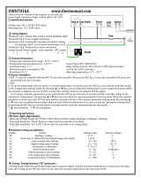
Figure 2a — Series V4 inputs and outputs.
Figure 2b - Controller dimensions.
Mounting Brackets
Front
Bezel
Terminal
Block
Mounting Slots
Terminal
Block
M3 Mounting Screw
Mounting Collar
External
Gasket
Customer's Front Panel
3.58"
(91.03mm)
4.21"
(106.83mm)
3.83"
(97.18mm)
4.25"
(107.9mm)
V4
1
2
%
Single Input -
Type J, K, T, N or
S Thermocouple,
RTD or Process
Output 1 -
Heat or Cool
Dual Control Output -
PID or ON/OFF, User Selectable
Output 2 -
Heat, Cool,
Alarm or None

Watlow Series V4 3
Installation and Removal
Figure 3 - Series V4 multiple panel cutout dimensions.
NOTE: Measurements between panel cutouts are the minimum recommended.
Installing the Series V4 Controller
Installing and mounting requires access to the back panel.
1. Make the panel cutout using the panel cutout dimensions as shown in Figure 4.
2. Make sure the rounded side of the external case gasket is facing the panel surface.
3. Check to see that the gasket is not twisted, and is seated within the case bezel flush with the panel.
4. Slightly compress the top and bottom side of the V4 Case while pulling the controller into the panel
cutout (Figure 5a). Slide the mounting collar over the back of the controller. The tabs on the collar
must line up with the mounting ridges on the case for secure installation. The tab holes are facing
the back of the controller.
5. Adjust the mounting bracket screws enough to allow for the mounting collar and panel thickness.
Snap the upper and lower mounting brackets on the case of the controller (Figure 5 b). Make sure
all the grips are well engaged on the mounting slots of the controller. (The four screw heads are fac-
ing the back of the controller.)
6. Make sure the case is seated properly. Tighten the installation screws firmly against the mounting
collar to secure the unit (Figure 5c). To ensure NEMA 4X seal, there should be no space
between the bezel and panel. Over tightening the screws will distort the case and make it diffi-
cult to remove or replace the controller.
V4
1
2
%
Panel Cutout
Panel
Thickness
0.375"
9.5 mm)
3.62"
(92mm)
3.62"
(92mm)
0.85"
(20mm)
minimum
0.85"
(20mm)
minimum
3.93"
(99.82mm)

Watlow Series V4 4
Installation and Removal (continued)
Figure 4a - Slightly compress the case while Figure 4b - Snap the top and bottom mounting
pulling the controller into the panel cutout. bracket into the slots.
Figure 4c - Tighten screw to secure the controller. Figure 4d - Remove the controller using a flat
screwdriver.
NOTE: Be careful not to over-tighten the screws. This may cause the mounting cover to fail. Over-tighten-
ing occurs when the front bezel is touching the customer’s front panel.
Removing the Series V4 Controller
1. Loosen the upper and lower mounting bracket screws.
2. Use a flat screw driver to unsnap the four grips on the opposite side of upper and lower mounting
brackets. Push the brackets back and forth gently until they can be pulled off easily.
3. Remove controller from the panel.

Watlow Series V4 5
Wiring the Series V4
Power Wiring
High Voltage
100 to 240VÅ (ac), nominal (85 to 264 actual) V4TH - _ _ _ _ - _ _ _ _
Low Voltage
14 to 24V‡ (ac/dc) V4TL - _ _ _ _ - _ _ _ _
Figure 5 - Power wiring.
Sensor Installation Guidelines
We suggest you mount the sensor at a location in your process or system where
it reads an average temperature. Put the sensor as near as possible to the
material or space you want to control. Air flow past this sensor should be mod-
erate. The sensor should be thermally insulated from the sensor mounting.
8
7
fuse
L1 L2
4
5
6
18
17
16
15
14
13
8
7
OFF
1 2
ç
WARNING:
To avoid damage to
property and equip-
ment and/or injury or
loss of life, use
National Electric
Code (NEC) standard
wiring practices to
install and operate
this unit. Failure to
do so could result in
injury and/or death,
or such damage.
NOTE:
Taking the unit out of
the case is not a nor-
mal operating condi-
tion and should only
be done by a quali-
fied maintenance
installation techni-
cian. Power to the
case should be dis-
connected before
removing or
installing the con-
troller into its case.
∫
WARNING:
The case terminals
may still carry live
voltage when the
unit is removed.
∫
WARNING:
Irreversible damage
will occur if high
voltage is applied to
the low voltage unit.

6 Watlow Series V4
Input Wiring
Figure 6a – Thermocouple
Extension wire for thermocouples must be of the same alloy as the thermo-
couple itself to limit errors.
Figure 6b – RTD (2- or 3-Wire) 100Ω Platinum
There could be a +2°F input error for every 1Ω of lead length resistance
when using a 2-wire RTD. That resistance, when added to the RTD element
resistance, will result in erroneous input to the instrument. To overcome
this problem, use a 3-wire RTD sensor, which compensates for lead length
resistance. When extension wire is used for a 3-wire RTD, all wires must
have the same electrical resistance (i.e. same gauge, same length, multiple-
stranded or solid, same metal.
Figure 6c – Process,4-20mA Figure 6d – Process,0-5VÎ (dc)
Input impedance: 5Ω Input impedance: 10kΩ
DIP Switch
Orientation
DIP Switch
Orientation
1: ON
2: ON
PROC
-
+
V
dc
4
5
6
5
6
OFF
1 2
OFF
1 2
- 4
+ 6
I
dc
PROC
DIP Switch
Orientation
1: ON
2: ON
DIP Switch
Orientation
OFF
1 2
4
5
6
OFF
1 2
2-wire RTD
Jumper Terminals 5 & 6
(customer supplied)
S1
S2
S3
4
5
6
DIP Switch
Orientation
DIP Switch
Orientation
1: OFF
2: OFF
RTD
OFF
1 2
4
5
6
OFF
1 2
OFF
1 2
3-wire
RTD
S1
S2
S3
4
5
6
DIP Switch
Orientation
DIP Switch
Orientation
1: OFF
2: OFF
RTD
4
5
6
OFF
1 2
DIP Switch
Orientation
TC
T/C
+
-
5
6
DIP Switch
Orientation
1: OFF
2: ON
OFF
1 2
4
5
6
OFF
1 2
NOTE:
Successful installa-
tion requires five
steps:
• Choose the con-
troller’s hardware
configuration and
model number;
• Choose a sensor;
• Install the con-
troller;
• Wire the controller
and
• Configure the con-
troller.
ç
WARNING:
To avoid damage to
property and equip-
ment and/or injury or
loss of life, use
National Electric
Code (NEC) standard
wiring practices to
install and operate
this unit. Failure to
do so could result in
injury and/or death,
or such damage.
NOTE: When an
external device with a
non-isolated circuit
common is connect-
ed to the 4-20mA or
dc output, you must
use an isolated or
ungrounded thermo-
couple.
ç
CAUTION: Process
input does not have
sensor break protec-
tion. Outputs can
remain full on.

Watlow Series V4
Output 1 Wiring
Figure 7a – Mechanical Relay
Without Contact Suppression
V4T _ - D _ _ _ - _ _ _ _
Form C, rated at 8A @ 125V~ (ac) or 5A @ 240V~ (ac)
Minimum load current: 100mA @ 5VÎ (dc)
Figure 7b – Solid State Relay
Without Contact Suppression
V4T _ - K _ _ _ - _ _ _ _
0.5 amps (AC loads only)
18
17
16
15
14
13
Customer Supplied
Quencharc
SS1
SS1
L2
L1
Fuse
External
Load
4
5
6
18
17
16
15
14
13
8
7
OFF
1 2
18
17
16
15
14
13
L1
L2
COM
NC
NO
External
Load
Fuse
Customer Supplied
Quencharc
4
5
6
18
17
16
15
14
13
8
7
OFF
1 2
ç
WARNING:
To avoid damage to
property and equip-
ment and/or injury or
loss of life, use
National Electric
Code (NEC) standard
wiring practices to
install and operate
this unit. Failure to do
so could result in
injury and/or death,
or such damage.
NOTE:
Switching inductive
loads (relay coils,
solenoids, etc.) with
the mechanical relay,
switched dc or solid-
state relay output
options requires use
of an R.C. suppres-
sor.
Watlow carries the
R.C. suppressor
Quencharc brand
name, which is a
trademark of ITW
Pakron. Watlow Part
No. 0804-0147-0000.

8 Watlow Series V4
Output 1 Wiring
Figure 8a – Switched DC, Open Collector
V4T _ - C _ _ _ - _ _ _ _
Figure 8b – 4-20mA Process
V4T _ - F _ _ _ - _ _ _ _
Maximum load impedance: 800Ω
18
17
16
15
14
13
External
Load
-
+
4
5
6
18
17
16
15
14
13
8
7
OFF
1 2
16
unregulated
V+
V—
18
Internal Circuitry
18
17
16
15
14
13
External
Load
-
+
4
5
6
18
17
16
15
14
13
8
7
OFF
1 2
NOTE:
When an external
device with a non-
isolated circuit com-
mon is connected to
the 4-20mA or dc out-
put, you must use an
isolated or unground-
ed thermocouple.

Watlow Series V4 9
Output 2 Wiring
Figure 9a – Mechanical Relay Without Contact Suppression
V4T _ - _ D _ _ - _ _ _ _
Form C, rated at 8A @ 125V~ (ac) or 5A @ 240V~ (ac). Minimum load cur-
rent: 100mA @ 5VÎ (dc)
Figure 9b – Solid State Relay Without Contact Suppression
V4T _ - _ K _ _ - _ _ _ _
0.5 amps (AC loads only)
18
17
16
15
14
13
Customer Supplied
Quencharc
SS2
SS2
L2
L1
Fuse
External
Load
4
5
6
18
17
16
15
14
13
8
7
OFF
1 2
18
17
16
15
14
13
L1
L2
COM
NC
NO
External
Load
Fuse
Customer
Supplied
Quencharc
4
5
6
18
17
16
15
14
13
8
7
OFF
1 2
Figure 93 – Switched DC, Open Collector
V4T _ - _ C _ _ - _ _ _ _
13
unregulated
V+
V—
15
Internal Circuitry
4
5
6
18
17
16
15
14
13
8
7
18
17
16
15
14
13
External
Load
-
+
1 2
OFF
1 2

Watlow Series V4 10
Wiring Example
Figure 10 - System wiring example.
1
120V~ (ac)
L1
L2
2
1
2
2
(+)
(-)
1CR
1
1 CR-1
2
TC+
TC-
DC+1
DC-1
L1 L2
Series V4
V4TH - CAAA - AARR
Temperature Controller
Series 94
94AA-1DK1-00RG
Limit Controller
NO1
NC1
TC-
L1
L2
TC+
Heater
DIN-a-mite
DA1C-1624-C000
1
COM1
(-)(+)
T1
T2
L1 L2
18
16
V4TH-CAAA-AARR
Temperature
Controller
L1
L2
120V~(ac)
fuse
process sensor limit sensor
coil
Heater
DIN-a-mite
DA1C-1624-C000
L2L1
T1 T2
Earth Ground
94AA-1DK1-00RG
Limit
Controller
7 (-)
6 (+)
fuse
fuses
high limit
mechanical
contactor
4
5
6
18
17
16
15
14
13
8
7
DIP Switch
Orientation
18
17
16
15
14
13
8
7
DIP Switch
Orientation
4
5
6
TC
TC
5 (+)
6 (-)
5 (+)
8
7
6 (-)
8
7
18
16
OFF
1 2
OFF
1 2
ç
WARNING:
To avoid damage to
property and equip-
ment and/or injury or
loss of life, use
National Electric
Code (NEC) standard
wiring practices to
install and operate
this unit. Failure to do
so could result in
injury and/or death,
or such damage.

Watlow Series V4 11
Keys and Displays
V4
1
2
%
Lower Display: Indicates
set point, output value,
parameters for data in the
upper display, or error and
alarm codes.
• To set to blank, set
[`dsP] to [`Pro] in the
Setup Menu.
Infinity/Home Key:
• Press once to clear
any latched alarms.
Also disables
deviation alarm
output if silencing is
enabled.
• Press again within
five seconds to
change from Auto to
Manual or vice versa.
While in Manual
mode, percent power
is in the lower display
sensor error.
Up-arrow and Down-arrow Keys:
Increases or decreases the value of
the displayed parameter.
• Press lightly to increase or
decrease the value by one.
• Press and hold down to increase
or decrease the displayed value at a
rapid rate. New data will self-enter
in five seconds, or can be entered by
pressing the Advance Key.
• Press both simultaneously for
three seconds to enter the Setup
Menu. The [`LOC] parameter
appears.
• Continue pressing both keys to
enter the Calibration Menu.
Output 1 Indicator Light: Lit
when Output 1 is energized.
Upper Display: Indicates
the process value, actual
temperature, operating
parameter values or an open
sensor. When powering up,
the Process display will be
blank for five seconds.
• To set to blank, set [`dsP]
to [`SEt] in the Setup
Menu.
Advance Key: Press to
advance through the
Operations, Setup, and
Calibration Menus. In the
Auto mode, new data is
self-entering in five
seconds.
Output 2 Indicator Light: Lit
when Output 2 is active. This
output can be configured as a
control or alarm output.
% Percent Power Indicator Light:
• Lit: the controller is in Manual
operation. Press the ˆInfinity key
twice to enter Automatic operation.
• Blinking: press the ˆInfinity key to
toggle between Auto and Manual.
Returns to its previous state and stops
blinking if the ˆInfinity key is not
pressed within five seconds.

Watlow Series V4 12
Setting up the Series V4 is a simple process. First set the DIP switches to match
your input type. Refer to the orientation on the back of the controller to select the
[``In] Input value. Next, configure the Series V4's features to your application
in the Setup Menu, then enter values in the Operating Menu. Both tasks use the
‰Advance key to move through the menus and the Up-arrow/Down-arrow keys to
select data.
Before entering information in the Setup Menu, set the [`dFL] parameter. If
[``SI] is selected, °C, proportional band in % of span, derivative and integral are
the defaults.If [``US] is selected, °F, proportional band in degrees,reset and rate
are the defaults. Changing the [`dFL] prompt will set parameters to their
factory default. Document all current parameter settings first. See the cal-
ibration section in the Appendix to change this parameter.
Entering the Setup Menu
The Operation Menu will appear as the default menu of the Series V4. The
Setup Menu displays the parameters that configure the Series V4's features to
your application.
Enter the Setup Menu by pressing the ¿Up-arrow and ¯Down-arrow keys si-
multaneously for 3 seconds.The lower display shows the [`LOC] Lock parame-
ter, and the upper display shows its current level. All keys are inactive until you
release both keys.You can reach the Lock parameter from anywhere.
Use the ‰Advance key to move through the menus and the ¿Up-arrow and
¯Down-arrow keys to select data. You will not see all parameters in this menu,
depending on the controller's configuration and model number. After stepping
through the menu it returns to the set point parameter under the Operation
Menu. If no keys are pressed for approximately 60 seconds, the controller
returns to the default display, Process over Set Point.
93
93
∫
WARNING:
Remove power from the
controller before remov-
ing the chassis from the
case or changing the DIP
switches. Removing the
controller from the chas-
sis is not a normal oper-
ating condition and
should only be done by a
qualified technician.
How to Set Up the Series V4
Figure 12a -
Entering the Setup Menu.
Figure 12b -
The Setup Menu.
NOTE:
While in the Setup
Menu, all outputs are off.
[`LOC] Lock
[``In] Input
[`dEC] Decimal*
[`C_F] Celsius - Fahrenheit*
[``rL] Range Low
[``rH] Range High
[`Ot1] Output 1
[`HSC] Hysteresis Control
[`Ot2] Output 2
[`HSA] Hysteresis Alarm*
[`LAT] Latching*
[`SIL] Silencing*
[`rtd] RTD*
[`rP`] Ramping
[`rT`] Rate*
[`P`L] Power Limiting*
[`dSP] Display
* Parameter may not always appear.
‰
Setup Menu

Watlow Series V4 13
At the top of the Setup Menu the Series V4 displays the user level of operation in
the upper display and the [`LOC] parameter in the lower display.
Press the ‰Advance key and the value of the next parameter appears in the
upper display, and the parameter appears in the lower display.
Lock: Selects the level of operator lock-out as defined below.
Range: 0 to 4 Default: 0
[```0]: All operating parameters may be viewed or changed. Manual operation
is permitted. When in manual operation, percent power is adjustable.
Bumpless transfer to manual mode will occur on sensor break.
[```1] The set point, process value and alarm settings are the only visible
parameters, set point is adjustable in this level. Manual operation and auto-
tune are permitted. When in manual operation, percent power is adjustable.
Bumpless transfer to manual mode will occur on sensor break.
[```2] The set point, process value and alarm settings are the only visible
parameters, set point is adjustable in this level. Manual operation is permit-
ted. When in manual operation, percent power is adjustable. Bumpless transfer
to manual mode will occur on sensor break.
[```3] The set point and process value are the only visible parameters, set
point is adjustable in this level. Manual operation is not permitted. Bumpless
transfer is defeated and outputs are disabled on sensor break.
[```4] The set point and process value are the only visible parameters, set
point is not adjustable in this level of lock-out. Manual operation is not per-
mitted. Bumpless transfer is defeated and outputs are disabled on sensor
break.
Input: Selects the sensor input type. The internal DIP switch must also match
the {`In} parameter. See DIP switch orientation, and see input type tempera-
ture ranges in the following chart.
Range: [```J], [```H] (K), [```t], [```n], [```S], [`rtd], [`r†d],
[`0-5], [`420] Default: J
Decimal: Selects the location of the decimal point for all process-related data.
This parameter only appears if the [``In] parameter is set to 0-5 or 420. Make
sure the internal DIP switch matches the [``In] parameter.
Range: 0, 0.0, 0.00 Default: 0
Celsius — Fahrenheit: Selects the units of temperature measurement for the
control. This parameter only appears if the [``In] parameter is set to a thermo-
couple or RTD input. The default is dependent on the [`dFL] parameter located
in the Calibration Menu. Refer to the Appendix.
Range: [```C] or [```F]
If [`dFL] is set to [``SI]: Default: [```C]
If [`dFL] is set to [``US]: Default: [```F]
Range Low: Selects the low limit of the set point. Also used to scale the low
end of the process input. 0.0VÎ (dc) and 4mA represent [``rL] Range Low for a
process input. The process input is linearly scaled between [``rL] and [``rH].
See the model number and specification in the Appendix for range values, or
refer to the following table.
Range: Sensor range low to [``rh] Range High
Default: Low limit of sensor type for a thermocouple or RTD. -500 for a process
input.
Setup Parameters
{``In}
{`dEC}
{`C-F}
ç
CAUTION:
A process input does not
have sensor break protection
or bumpless transfer.
NOTE:
Shaded parameters may not
appear, depending on the
controller’s configuration
and model number.
ç
CAUTION:
Changing [``In] sets all
parameters to factory
defaults. Document all set-
tings before changing this
parameter.
NOTE:
Set the [`LOC] parameter
value as the final step in
programming the Series V4
controller to prevent locking
yourself out of the Operation
and Setup Menu during ini-
tial programming.
[`LOC}
{``rL}

Watlow Series V4 14
{`HSC}
{`Ot1}
{`Ot2}
{`HSA}
{``rh}
{`LAt}
{`SIL}
{`rtd}
{``rt}
{`rP`}
Range High: Selects the high limit of the operating range. Also used to scale the
high end of the process input. 5.0VÎ (dc) and 20mA represent Range High [``rh]
for a process input. The process input is linearly scaled between [``rL] and
[``rH]. See the model number and specification information in the Appendix for
your range values, or refer to the following table.
Range: Sensor range high to [``rL]
Default: High limit of sensor type for a thermocouple or RTD. 9999 for process input.
Output 1: Selects the action for the primary output in response to the difference
between set point and process variable. Select [``ht] (heat) for reverse acting or
select [``CL] (cool) for direct acting.
Range: [``ht], [``CL] Default: [``ht]
Hysteresis-Control: Selects the switching hysteresis for Output 1 and 2 when you
select 0 (on-off) under the [`Pb1] parameter and [`Ot2] is set to [`Con].
Range: 1 to 55, 0.1 to 5.5, 0.01 to 0.55°C/1 to 99, 0.1 to 9.9, 0.01 to 0.99°F
Default: 2, 0.2, 0.02°C/3, 0.3, 0.03°F
Output 2: Selects the output action for the secondary output.
Range:
[`Con] Control mode opposite Output 1 (heat or cool)
[`PrA] Process alarm with alarm message displayed
[``Pr] Process alarm with no alarm message displayed
[`dEA] Deviation alarm with alarm message displayed
[``dE] Deviation alarm with no alarm message displayed
[``no] None
Default: [`Con]
Hysteresis - Alarm: Selects the switching hysteresis for Output 2 when [`Ot2] is
an alarm. Appears only if [`Ot2] is not set to [`Con] or [``no]. See the Operation
Menu for [`Pb1].
Range: 1 to 5555, 0.1 to 555.5, 0.01 to 55.5°C/1 to 9999, 0.1 to 999.9, 0.01 to 99.99°F
Default: 2, 0.2, 0.02°C/3, 0.3, 0.03°F
Latching: Selects whether the alarm is latching or non-latching. Latching alarms
must be cleared by pressing the ˆInfinity key before the alarm output will reset.
Selecting non-latching will automatically reset the alarm output when the condition
clears. Appears only if [`Ot2] is not set to [`Con] or [``no].
Range: [`LAt] or [`nLA] Default: [`nLA]
Silencing: Selects alarm silencing (inhibit) for the alarm. Appears only when
[`Ot2] is set to [`dEA] or [``dE]. For more information see Chapter 5.
Range: [``On] or [`OFF] Default: [`OFF]
RTD: Selects the RTD calibration curve for RTD inputs. Will not appear unless
[``In] is set to [`rtd] or [`r†d]. [`JIS] is 0.003916Ω/Ω°C, [`Din] is
0.003850Ω/Ω°C.
Range: [`din] or [`JIS] Default: [`din]
Ramping: Choose [`Str], and the set point ramps at the selected rate in °/hr. from
the process (actual) temperature to the set point, when power is applied to the con-
troller (start up). It will not ramp with a set point change. [`On] is the same as
[`Str], but ramps with a set point change. It ramps from the previous set point to a
new one at the selected ramp rate. Select [`OFF] for no ramping action. When
ramping, the lower display alternately flashes [``rP]. The set point displayed is the
desired end set point. The ramping set point is not shown. Entering the Setup Menu
or manual operation disables the outputs and ramp. Once you exit either one, the
Series V4 controls to the last entered set point.
Range: [`Str], [``On], [`OFF] Default: [`OFF]
Rate: Selects the ramping rate in degrees per hour. Will not appear if [``rP] is set
to [`OFF].
Range: 0 to 9999 Default: 100°/hr.

Watlow Series V4 15
Power Limiting: The power limiting function in % power for heat only. Power
Limiting will function if [`pb1] is set to [```0].
Range: Dependent on output type. 0 to100 Default: 100
Display: Selects which displays are active or viewable. Five seconds after selected,
the appropriate display goes blank. Press ‰Advance, ¿Up-arrow or ¯Down-arrow
to override this feature and cause the current value to be displayed for 5 seconds.
Range: [`nor]Normal displays Default: [`nor]
[`SEt] Set Point - lower display only
[`Pro] Process - upper display only
Setup Menu
Parameter Value Range Factory Default Appears If:
[`LOC]
**
[```0], [```1], [```2], [```3], [```4] 0
[``In] [```J], [```H], [```t], [```n], [```J] DIP switch selectable.
[```S], [`rtd], [`r†d], [`0-5], [`420]
[`dEC] 0, 0.0, 0.00 0 [``In] is set to [`0-5]
or [`420]
[`C_F] [```C] or [```F] Dependent on [`dFL] [``In] is set to [```J],
[```H], [```t], [```n],
[```S], [`rtd], or [`r†d]
[``rL] [``rL] to [``rh] Input dependent.
[``rh] [``rh] to [``rL] Input dependent.
[`Ot1] [``ht] or [``CL] [``ht]
[`HSC] 1 - 99, 0.1 - 9.9, 0.01 - 0.99°F 3, 0.3, 0.03°F
1 to 55, 0.1 to 5.5, 0.01 to 0.55°C 2, 0.2, 0.02°C
[`Ot2] [`Con] = Control [`Con]
[`PrA] = Process Alarm
[``Pr] = Process with no alarm message
[`dEA] = Deviation alarm
[``dE] = Deviation with no alarm message
[``no] = None
[`HSA] 1 - 9999, 0.1 - 999.9, 0.01 - 99.99°F 3, 0.3, 0.03°F [`Ot2] is not set to [`Con]
1 - 5555, 0.1 - 555.5, 0.01 - 55.55°C 2, 0.2, 0.02°C or [``no]
[`LAt] [`LAt] or [`nLA] [`nLA] [`Ot2] is not set to [`Con]
or [``no]
[`SIL] [``On] or [`OFF] [`OFF] [`Ot2] is set to [`dEA] or
[``dE]
[`rtd] [`JIS] or [`din] [`din] [``In] is set to [`rtd] or
[`r†d]
[`rP`] [`Str] is set to Ramping on power up [`OFF]
[``on] is set to Ramping to set point always
[`OFF] is set to None
[`rt`] 0 to 9999 100°/hr [``rP] is not set to [`OFF]
[`P`L] 0 to 100 100
[`dsP] [`nor] = normal [`nor]
[`SEt] = Set Point (lower only)
[`Pro] = Process (upper only)
**LOC Functions
[```0]
: All operating parameters may be viewed or changed. Manual operation is permitted. Bumpless transfer to manual
mode will occur on sensor break.
[```1]
: The set point, actual, and alarm settings are only visible parameters, set point is adjustable in this level. Manual
operation and auto-tune are permitted. Bumpless transfer to manual mode will occur on sensor break.
[```2]
: The set point, actual, and alarm settings are the only visible parameters, set point is adjustable in this level. Manual
operation is permitted. Bumpless transfer to manual mode will occur on sensor break.
[```3]
: The set point and actual are the only visible parameters, set point is adjustable in this level. Manual operation is not
permitted. Bumpless transfer is defeated and outputs are disabled on sensor break.
[```4]
: The set point and actual are the only visible parameters, set point is not adjustable in this level. Manual operation is
not permitted. Bumpless transfer is defeated and outputs are disabled on sensor break.
Input Type Sensor Range Low Sensor Range High
[```J] 0°C/32°F 750°C/1382°F
[```H] -200°C/-328°F 1250°C/2282°F
[```t] -200°C/-328°F 350°C/662°F
[```n] 0°C/32°F 1250°C/2282°F
[```S] 0°C/32°F 1450°C/2642°F
[`rtd] (1°) -200°C/-328°F 700°C/1292°F
[`r†d] (0.1°) -128.8°C/-199.9°F 537.7°C/999.9°F
[`420] 4mA/-999 units 20mA/9999 units
[`0-5] 0VÎ (dc)/-999 units 5VÎ (dc)/9999 units
Table 15a -
Input Ranges.
{`dSP}
Table 15b -
Setup Menu Prompts
and Descriptions.
[`P`L]

Watlow Series V4 16
Operation Parameters
Set Point: Sets the operating set point for Output 1. Represents the process value the
system tries to achieve for Output 1. "SP" does not appear on the lower display. The
control set point value is displayed and can be incremented or decremented without
pressing the ‰Advance key. The lower display may be blank if [`dSP] is set to
[`Pro]. In a ramping mode, the lower display alternately flashes the desired end set
point and [``rP].
Proportional Band 1 and 2: A proportional band, expressed in degrees or % of
span, within which a proportioning function is active for Output 1 or 2. When
[`Pb1] is set to 0, the unit functions as an on-off control on Output 1 and 2. [`Pb2]
will not appear if [`Pb1] is set to 0 or [`Ot2] is not set to [`Con]. The switching
differential is determined by the [`HSC] parameter.
Range if [`dFL] is set to [``US]: [`Pb1]: 0 to 555°C/0 to 999°F/0 to 999 Units; 0.0
to 5.5°C/0.0 to 9.9°F/0.0 to 9.9 units, [`Pb2]: The same as [`Pb1] except lower limit
is 1 or 0.1. Defaults: [`Pb1] is set to 2.5°C/25°F [`Pb2] is set to 25
Range if [`dFL] is set to [``SI]: 0 to 999.9% of span
Defaults: [`Pb1] is set to 3.0% [`Pb2] is set to 3.0%
Reset /Integral 1 and 2: An integral control action for Output 1 or 2 that auto-
matically eliminates offset, or "droop," between set point and actual process temper-
ature. [`rE1]/[`It1]: Will not appear if [`Pb1] is set to 0. [`rE2]/[`It2]:
Appears if [`Pb1] is not set to 0 and [`Ot2] is set to [`Con]. Either reset [``rE]
or integral [``It] will appear depending on how the [`dFL] parameter is set in the
Calibration Menu. See the Appendix.
Range if [`dFL] is set to [``US]: 0 to 9.99 repeats/minute Default: 0.00
Range if [`dFL] is set to [``SI]: 00.1 to 9.99 minutes per repeat Default: 0.00
Rate/Derivative 1 and 2: The rate (derivative) function for Output 1 or Output 2.
Eliminates overshoot on startup, or after the set point changes. [`rA1]/[`dE1]:
Will not appear if [`Pb1] is set to 0. [`rA2]/[`dE2]:Appears if [`Pb1] is not set to
0 and [`Ot2] is set to [`Con]. Either rate [``rA] or derivative [``dE] appears de-
pending on how [`dFL] is set in the Calibration Menu.
Range if [`dFL] is set to [``US] or [``SI]: 0 to 9.99 minutes Default: 0.0
Cycle Time 1 and 2: Time for a controller to complete one time-proportioned cycle
for Output 1 or Output 2; expressed in seconds. [`Ct1]:Will not appear if [`Pb1] is
set to 0, or Output 1 is 4-20mA. [`Ct2]: Will not appear if [`Pb1] is set to 0 or
[`Ot2] is not set to [`Con].
NOTE:
Shaded parameters
may not appear,
depending on the
controller’s configu-
ration and model
number.
[``SP}
NOTE:
The upper display
will always return to
the process value
after 1 minute with-
out key strokes.
{`rE1}
{`It1}
{`rE2}
{`It2}
{`Ct1}
{`Ct2}
{`rA1}
{`dE1}
{`rA2}
{`dE2}
{`Pb1}
{`Pb2}
[``93] Control Set Point
[`Pb1] Proportional Band 1
[`rE1] Reset 1*
[`It1] Integral 1*
[`rA1] Rate 1*
[`dE1] Derivative 1*
[`Ct1] Cycle Time 1*
[`ALO] Alarm Low*
[`AHI] Alarm High*
[`Pb2] Proportional Band 2*
[`rE2] Reset 2*
[`It2] Integral 2*
[`rA2] Rate 2*
[`dE2] Derivative 2*
[`Ct2] Cycle Time 2*
[`CAL] Calibration Offset
[`AUt] Autotune
‰
Operation Menu
* Parameter may not always appear.
Operation Menu
Figure 16 -
The Operation Menu.

Watlow Series V4 17
If a mechanical relay or contactor is switching power to the load, a longer
cycle time may be desirable to minimize wear on the mechanical compo-
nents. Typical life of a mechanical relay is 100,000 cycles.
Range: 0.1 to 999.9 seconds Default: 5.0 seconds
Alarm Low: Represents the low process alarm or low deviation alarm. This param-
eter will not appear if [`Ot2] is set to no or [`Con].
Range if [`Ot2] is set to [`dEA] or [``dE]: -999 to 0 Default: -999
Range if [`Ot2] is set to [`PrA] or [``Pr]: [``rL] to [`AHI] Default: [``rL]
Alarm High: Represents the high process alarm or high deviation alarm. This
parameter will not appear if [`Ot2] is set to [``no] or [`Con].
Range if [`Ot2] is set to [`dEA] or [``dE]: 0 to 999 Default: 999
Range if [`Ot2] is set to [`PrA] or [``Pr]: [`ALO] to [``rH] Default: [``rH]
Calibration Offset: Adds or subtracts degrees from the input signal.
Range: -100°C to 100°C/-180°F to 180°F/-180 units to 180 units; or
-10.0°C to 10.0°C/-18.0°F to 18.0°F Default: 0
Autotune: Initiates an autotune.
Range: 0 is set to off, 1 is set to slow, 2 is set to medium, 3 is set to fast
Default: 0
Table 17 -
Operation Menu
Prompts and
Descriptions.
{`ALO}
Operation Menu Parameters
Document your Series V4 Operation Parameters.
{`AHI}
{`AUt}
{`CAL}
Parameter Value Range Factory Default
[`Pb1] If [`dFL] is set to [``US]:
0 - 999°F/0 - 555°C/0 - 999 Units 25°F
0 - 99.9°F/0 - 55.5°C/0 - 99.9 Units 2.5°F
0 is set to ON/OFF control. [`HSC] is set to switch diff.
If [`dFL] is set to [``SI]: 0.0 to 999.9% of span 3%
[`rE1] 0.00 to 9.99 repeats/minute 0.00 repeats/minute
0.00 = No Reset. Won't appear if [`Pb1] is set to 0
or [`dFL] is set to [``SI].
[`It1] 0.0 - 99.9 minutes/rpt. 0.00 = No Integral. 00.0 minutes/repeat
Won't appear if [`Pb1] is set to 0 or [`dFL] is set to [``US].
[`rA1] 0.00 to 9.99 minutes 0.00 minutes
0.00 = No Rate. Will not appear if [`Pb1] is set to 0
or [`dFL] is set to [``SI].
[`dE1] 0.00 - 9.99 minutes. 0.00 = No Derivative. 0.00 minutes
Won't appear if [`Pb1] is set to 0 or [`dFL] is set to [``US].
[`Ct1] 0.1 to 999.9 5.0 seconds
Won't appear if [`Pb1] = 0, or [`420].
[`Pb2] Same as [`Pb1]. [`Pb2] lower limit = 1, 0.1, 0.01
[`rE2] Same range as [`rE1].
[`It2] Same range as [`It1].
[`rA2] Same range as [`rA1].
[`dE2] Same range as [`dE1].
[`Ct2] Same range as [`Ct1].
[`ALO]
Deviation [``dE] -999 to 0 -999
Process [``Pr] [``rL] to [`AHI] [``rL]
Will not appear if [`Ot2] is set to [``no] or [`Con].
[`AHI]
Deviation [``dE] 0 to 999 999
Process [``Pr] [`ALO] to [``rH] [``rH]
Will not appear if [`Ot2] is set to [``no] or [`Con].
[`CAL] ±180°F/±100°C/±180 Units 0
[`AUt] 0-3 0

18 Watlow Series V4
Troubleshooting Alarms and Errors
Indication Probable Cause(s) Corrective Action
Error Code Messages ([----] in the upper display indicates a Series V4 error; error code number is visible in
bottom display)
• Sensor input generated a value lower than allowable
signal range, or A/D circuitry malfunctioned. Enter a
valid input. Make sure
[``In]
parameter (Setup
Menu) matches your sensor and DIP switches are set
accordingly.
• Microprocessor is faulty; consult factory.
• Unless power interruption occurred while controller
was storing data, nonvolatile memory is bad; consult
factory.
• A/D circuit is underrange. Check sensor; if function-
ing properly, consult factory. Make sure
[``In]
parameter (Setup Menu) matches your sensor and
DIP switches are set accordingly.
• A/D circuit is overrange. Check sensor; if functioning
properly, consult factory. Make sure
[``In]
parame-
ter (Setup Menu) matches your sensor and DIP
switches are set accordingly.
• Sensor underrange error (applies
only to RTD units)
• Configuration error.
• Non-volatile checksum error.
• A/D underflow error.
• A/D overflow error.
• [----] [`Er2]
• [----] [`Er4]
• [----] [`Er5]
• [----] [`Er6]
• [----] [`Er7]
• Check the alarm logic for compatibility with system
peripherals and annunciators.
• Check the power limit setting
• Check the operation mode.
• Check the alarm output function.
• Check the °C or °F setting.
• Check the calibration offset value; set it to a lower
level.
• Alarm may be latched.
• Alarm set points may be incorrect..
• Alarm hysteresis may be incorrect.
• Input may be in error condition.
• Alarm won’t
occur.
• Configure output as an alarm.
• Check alarm set points.
• To clear the alarm, correct the alarm condition; check
to see if the alarm is latched.
• Check the alarm sides setting.
• Check the alarm type setting.
• Alarm output may be off.
• Alarm set points may be incorrect.
• Alarm may be silenced.
• Alarm sides may be incorrect.
• Controller may be in diagnostics
mode.
• Alarm won’t
occur.
Alarms
• Check switches, fuses, breakers, interlocks, limits,
connectors, etc. for energized condition and proper
connection.
• Measure power upstream for required level. Check part
number for input power required.
• Check wire size.
• Check for bad connections.
• Power to unit may be off.
• Fuse may be blown.
• Breaker may be tripped.
• Safety interlock door switch, etc.
may be activated.
• Separate system limit control
may be latched.
• Wiring may be open.
• Input Power may be incorrect.
• No power.
Power

Watlow Series V4 19
Calibration
Before attempting to calibrate, make sure you read through
the procedures carefully and have the proper equipment
called for in each procedure. Make sure the DIP switches
are in the proper position for the input type.
Entering the Calibration Menu
In the Calibration Menu, various input signals must be supplied for the con-
troller to go through its auto calibration. The Calibration Menu can only be
entered from the [`LOC] Lock parameter in the Setup Menu. Press the ¿Up-
arrow/¯Down-arrow keys simultaneously for 3 seconds (± 1 second). The [`CAL]
parameter appears in the lower display with "no" in the upper display.
Any inadvertent change in the displayed data, when pressing the ¿Up-
arrow/¯Down-arrow keys, is ignored. Calibration values won't be retained unless
you are in the manual mode. Press the ¿Up-arrow or ¯Down-arrow key to change
the upper display to [`YES] Press ‰Advance to enter the calibration sequence.
Upon entering the calibration menu, the upper display window indicates [`CAL].
It continues to indicate [`CAL] (with the exception of calibration of the 4-20mA
output) while the operator walks through the entire calibration parameter list.
While calibrating the 4-20mA output, the upper display contains a numeric
value to be slewed up or down until the output value is correct. The controller
uses the lower display to prompt the user as to what the input should be.
With the [`dFL] parameter, select either [``US] parameters which include dis-
playing °F, rate, reset, and proportional band in degrees or units. Or select
[``SI] (System International) and the displayed parameters are °C, integral,
derivative, and proportional band in % of span.
Once the information has been properly established and maintained for at least
5 to 10 seconds, the ‰Advance key may then be used to display the next prompt.
After the final input is established, press the ‰Advance key twice to return the
controller to the configuration menu at the top of the parameter list.
Figure 19 -
Entering the
Calibration Menu.
NOTE:
While in the Calibration
Menu, the controller out-
put(s) go off and the
alarm output (if present)
is on.
NOTE:
Calibration values will
not be retained unless
you are in the MANUAL
mode. Do not enter the
MANUAL mode until you
are at the correct input
parameters.
V4
1
2
%
V4
1
2
%
The [`rSt] parameter restores the factory calibration values to the Series V4. If
you calibrate your control incorrectly, you have the option to default to the origi-
nal values. Once you leave the [`CAL] menu, the values are entered.
1. Press the ¿Up-arrow/¯Down-arrow keys simultaneously for three seconds.
The LOC parameter appears in the lower display. Continue holding the
¿Up-arrow/¯Down-arrow keys until the lower display reads [`CAL].
2. Press the ¿Up-arrow key until [`YES] appears in the upper display.
3. ‰Advance through the calibration menu until [`rSt] appears in the lower
display.
4. Press the ¿Up-arrow key until [`YES] appears in the upper display.
5. Press the ‰Advance key and the V4 advances to test the displays.
6. To conclude, wait 60 seconds or press the ‰Advance key to reach the next
prompt or to exit from the CAL menu.
This procedure is used only to restore calibration, it is not meant to clear values.
Restoring Factory Calibration

20 Watlow Series V4
Calibration Menu
[`)00] Input 0.00mV for low input.
[`5)0]
Input 50.00mV for high input.
[``tC]
Connect a Type "J" ambient compensator with inputs shorted.
[`440] Set the low resistance to 44.01Ω.
[`225] Set the high resitance to 255.42Ω.
[`)00]
Set the voltage source to 0.000 volts.
[`%00] Set the voltage source to 5.000 volts.
[`$00] Set the cursource to 4.00mA
[`2)0] Set the current source to 20.00mA
[`4A0] Enter 4-20mA output calibration value for 4mA
[`2A0] Enter 4-20mA output calibration value for 20mA
[`rSt] Restores factory calibration values.
[`dSP] Test display.
[`dFL] Select US (rate, reset, proportional band in degrees or units, °F) or
SI (integral, derivative, proportional band in % of span, °C)
Calibration Menu
[``NO]
[`CAL]
[`YES]
[`CAL]
‰
‰
‰
Figure 20 -
Calibration Parameters.
NOTE:
Before calibration on an
installed controller,
make sure all data and
parameters are docu-
mented.
Equipment Required
• Type "J" Reference Compensator with reference junction at 32°F/0°C, or Type "J"
Thermocouple Calibrator set at 32°F/0°C.
• Precision millivolt source, 0-50mV min. range, 0.01mV resolution
Setup And Calibration
1. Connect the ac line voltage L1 and L2 to the proper terminals.
2. Connect the millivolt source to Terminal 6 Negative and Terminal 5 Positive on the
Series V4 terminal block. Use regular 20 - 24 gauge wire. Make sure the DIP switch is
set for thermocouple input.
3. Apply power to the controller and allow it to warm up for 15 minutes. After warm-up
put the controller in the Calibration Menu. Select [`YES].
4. Press the ˆInfinity key twice to enter the manual mode. The controller is calibrating
when % indicator light is on. Make sure the controller is in manual mode only when
you are in the correct parameters.
5. At the 0.00 prompt, enter 0.00mV from the millivolt source to the control.Allow at
least 10 seconds to stabilize. Press the
‰Advance key.
6. At the 50.0 prompt, enter 50.00mV from the millivolt source to the Series V4. Allow at
least 10 seconds to stabilize. Press the ‰Advance key.
7. At the [``tC] prompt, disconnect the millivolt source, and connect the reference com-
pensator or thermocouple calibrator to Terminal 6 Negative, and Terminal 5 Positive
on the Series V4 terminal block. If using a compensator, turn on and short the input
wires. If using "J" calibrator, set to simulate 32°F/0°C. Allow 10 seconds for the control
to stabilize. The controller will leave the [`CAL] mode if one minute passes between
key activations. Press the ˆInfinity key twice to exit the manual mode. To conclude the
thermocouple calibration, advance the
‰Advance key to the next prompt or exit the
[`CAL] menu.
Thermocouple Field Calibration Procedure
/