Page is loading ...

0600-0021-0000 Rev E Made in the U.S.A.
July 2005 $15.00
Supersedes: 0600-0021-0000 Rev D
User’s Manual
User Levels:
• New User ....................................................... go to page 1.1
• Experienced User .......................................... go to page 2.1
• Expert User .................................................... go to page 2.1
Installers:
• Installation ...................................................... go to page 2.1
• Wiring .............................................................go to page 3.1
1241 Bundy Blvd., P.O. Box 5580, Winona, Minnesota USA 55987-5580
Phone: (507) 454-5300, Fax: (507) 452-4507 http://www.watlow.com
Registered Company
Winona, Minnesota USA
ISO 9001
TOTAL
3 Year Warranty
CUSTOMER
SATISFACTION
Series 97

Safety Information
We use note, caution and warning symbols throughout this book to draw your
attention to important operational and safety information.
A “NOTE” marks a short message in the margin to alert you to an important
detail.
A “CAUTION” safety alert appears with information that is important for pro-
tecting your equipment and performance. Be especially careful to read and fol-
low all cautions that apply to your application.
A “WARNING” safety alert appears with information that is important for pro-
tecting you, others and equipment from damage. Pay very close attention to all
warnings that apply to your application.
The safety alert symbol,
ç
, (an exclamation point in a triangle) precedes a
general CAUTION or WARNING statement.
The electrical hazard symbol,
Ó
, (a lightning bolt in a triangle) precedes an
electric shock hazard CAUTION or WARNING safety statement.
Technical Assistance
If you encounter a problem with your Watlow controller, see the Trouble-
shooting Table in the Appendix and review all of your configuration informa-
tion to verify that your selections are consistent with your application: inputs;
outputs; alarms; limits; etc. If the problem persists after checking the above,
you can get technical assistance from your local Watlow representative, or by
dialing (507) 454-5300.
An applications engineer will discuss your application with you.
Please have the following information available when calling:
• Complete model number • All configuration information
• User’s Manual • Diagnostic menu readings
Your Feedback
Your comments or suggestions on this manual are welcome. Please send them
to: Technical Writer, Watlow Winona, 1241 Bundy Blvd., P.O. Box 5580,
Winona, MN 55987-5580; phone: (507) 454-5300; fax: (507) 452-4507. The
Series 97 User’s Manual is copyrighted by Watlow Winona, Inc., © July 2005,
with all rights reserved. (2194)
NOTE:
Details of a “Note”
appear here in the
narrow margin on the
outside of each
page.
CAUTION:
Details of a
“Caution” appear
here in the narrow
margin on the out-
side of each page.
WARNING:
Details of a
“Warning” appear
here in the narrow
margin on the out-
side of each page.

Chapter 1: Overview . . . . . . . . . . . . . . . . . . . . . . .1.1
Chapter 2: Installation . . . . . . . . . . . . . . . . . . . . . .2.1
Chapter 3: Wiring . . . . . . . . . . . . . . . . . . . . . . . . . .3.1
Power Wiring . . . . . . . . . . . . . . . . . . . . . . . . .3.3
Sensor Installation Guidelines . . . . . . . . . . . .3.3
Wiring Example . . . . . . . . . . . . . . . . . . . . . . .3.4
Wiring Notes . . . . . . . . . . . . . . . . . . . . . . . . .3.5
Input 1 . . . . . . . . . . . . . . . . . . . . . . . . . . . . . .3.6
Input 2 . . . . . . . . . . . . . . . . . . . . . . . . . . . . . .3.6
Output 1 . . . . . . . . . . . . . . . . . . . . . . . . . . . . .3.7
Output 2 . . . . . . . . . . . . . . . . . . . . . . . . . . . . .3.8
Output 3 . . . . . . . . . . . . . . . . . . . . . . . . . . . . .3.9
Output 4 . . . . . . . . . . . . . . . . . . . . . . . . . . . . .3.10
Chapter 4: Software Navigation . . . . . . . . . . . . . . .4.1
Keys and Displays . . . . . . . . . . . . . . . . . . . . .4.2
Navigation . . . . . . . . . . . . . . . . . . . . . . . . . . .4.3
Software Map . . . . . . . . . . . . . . . . . . . . . . . . .4.4
Task Charts . . . . . . . . . . . . . . . . . . . . . . . . . . 4.6
Chapter 5: Features. . . . . . . . . . . . . . . . . . . . . . . . 5.1
Limit. . . . . . . . . . . . . . . . . . . . . . . . . . . . . . . . 5.2
Input . . . . . . . . . . . . . . . . . . . . . . . . . . . . . . .5.3
Alarms . . . . . . . . . . . . . . . . . . . . . . . . . . . . . .5.8
Communications . . . . . . . . . . . . . . . . . . . . . .5.11
Chapter 6: Parameters . . . . . . . . . . . . . . . . . . . . . 6.1
Home Page . . . . . . . . . . . . . . . . . . . . . . . . . .6.3
Operations Page . . . . . . . . . . . . . . . . . . . . . . 6.4
Setup Page . . . . . . . . . . . . . . . . . . . . . . . . . . 6.7
Factory Page . . . . . . . . . . . . . . . . . . . . . . . . . 6.17
Appendix. . . . . . . . . . . . . . . . . . . . . . . . . . . . . . . . A.1
Troubleshooting . . . . . . . . . . . . . . . . . . . . . . . A.2
Modbus™ RTU . . . . . . . . . . . . . . . . . . . . . . . A.4
Calibrating the Series 97 . . . . . . . . . . . . . . . . A.11
Glossary . . . . . . . . . . . . . . . . . . . . . . . . . . . . A.14
Specifications . . . . . . . . . . . . . . . . . . . . . . . . A.18
Ordering Information . . . . . . . . . . . . . . . . . . . A.20
Index . . . . . . . . . . . . . . . . . . . . . . . . . . . . . . . A.21
Prompt Index . . . . . . . . . . . . . . . . . . . . . . . . . A.23
Declaration of Conformity. . . . . . . . . . . . . . . . A.24
Parameter setup order . . . . . . . . . . . . . . . . . . A.25
Fold out Software Map. . . . . . . . . . . . . A.25 - A.26
Warranty and Returns . . . . . . . . . . . . back cover
Figures and Tables
Inputs and outputs . . . . . . . . . . . . . . . . . . . . . . . . .1.1
Multiple panel cutout dimensions . . . . . . . . . . . . . .2.1
Installing the controller . . . . . . . . . . . . . . . . . . . . . .2.2a
Gap dimensions . . . . . . . . . . . . . . . . . . . . . . . . . . .2.2b
Removing the controller . . . . . . . . . . . . . . . . . . . . .2.3
Isolation blocks . . . . . . . . . . . . . . . . . . . . . . . . . . .3.2
Power wiring . . . . . . . . . . . . . . . . . . . . . . . . . . . . .3.3
Wiring example . . . . . . . . . . . . . . . . . . . . . . . . . . .3.4
Wiring notes . . . . . . . . . . . . . . . . . . . . . . . . . . . . .3.5
Input 1 Wiring
Thermocouple . . . . . . . . . . . . . . . . . . . . . . . .3.6a
RTD (2- or 3-Wire) 100Ω platinum . . . . . . . . .3.6b
Input 2 Wiring
Digital Event . . . . . . . . . . . . . . . . . . . . . . . . . .3.6c
Output 1 Limit Output Wiring
AC Outputs . . . . . . . . . . . . . . . . . . . . . . . . . .3.7a
Output 2 Alarm Output Wiring
AC Outputs . . . . . . . . . . . . . . . . . . . . . . . . . .3.8a
Switched DC, Open Collector . . . . . . . . . . . . . . . . .3.8b
Output 3 Alarm Wiring
AC Outputs . . . . . . . . . . . . . . . . . . . . . . . . . .3.9
Output 4 wiring
AC Outputs . . . . . . . . . . . . . . . . . . . . . . . . . .3.10a
Communications and Retransmit . . . . . . . . . .3.10b
EIA-232 to EIA-435 Conversion . . . . . . . . . . . . . . .3.11a
EIA-232 to EIA-485 Converter . . . . . . . . . . . .3.11b
Keys and displays . . . . . . . . . . . . . . . . . . . . . . . . .4.2
Navigating the Series 97 . . . . . . . . . . . . . . . . . . . .4.3
Software Map . . . . . . . . . . . . . . . . . . . . . . . . . . . .4.4
Calibration offset . . . . . . . . . . . . . . . . . . . . . . . . . .5.3
Filtered and unfiltered input signals . . . . . . . . . . . .5.4
Sensor ranges . . . . . . . . . . . . . . . . . . . . . . . . . . . .5.5
Event inputs . . . . . . . . . . . . . . . . . . . . . . . . . . . . . .5.6
Retransmitting a remote set point . . . . . . . . . . . . . .5.7
Alarm settings . . . . . . . . . . . . . . . . . . . . . . . . . . . .5.8
Alarm latching . . . . . . . . . . . . . . . . . . . . . . . . . . . .5.9
Alarm silencing . . . . . . . . . . . . . . . . . . . . . . . . . . .5.10
Parameter setup order . . . . . . . . . . . . . . . . . . . . . .6.2
. . . . . . . . . . . . . . . . . . . . . . . . . . . . .inside back cover
T
Series 97
Table of Contents

TOTAL
3 Year Warranty
CUSTOMER
SATISFACTION
About Watlow Winona
Watlow Winona is a division of Watlow Electric Mfg. Co., St. Louis, Missouri, a
manufacturer of industrial electric heating products, since 1922. Watlow begins
with a full set of specifications and completes an industrial product that is
manufactured totally in-house, in the U.S.A.. Watlow products include electric
heaters, sensors, controllers and switching devices. The Winona operation has
been designing solid state electronic control devices since 1962, and has earned
the reputation as an excellent supplier to original equipment manufacturers.
These OEMs depend upon Watlow Winona to provide compatibly engineered
controls which they can incorporate into their products with confidence. Watlow
Winona resides in a 100,000 square foot marketing, engineering and
manufacturing facility in Winona, Minnesota.
ii ■ Table of Contents Watlow Series 97

Chapter One
Overview
Introduction
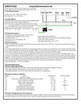
Watlow’s Series 97 is a microprocessor-based controller with a single input, second auxiliary
input and four outputs. Input 1 is used to measure temperature from a thermocouple or
RTD sensor. Input 2 can be utilized as a remote reset switch or a hardware lockout switch.
With up to four outputs, the controller is versatile in handling applications that require a
high/low limit, alarms, retransmit and communications. The controller is so user friendly it
can be set up to display safety and limit messages created by the end user to meet the exact
application need.
The Series 97 limit controller is added to thermal applications to limit over-temperature
conditions. The Series 97 controller provides safety assurance against instances where a
high temperature runaway condition could occur from a shorted input sensor or an output
device that could fail in a closed position.
The Series 97 is recommended for any application where thermal runaway could result in
large product scrap costs, affect operator safety, cause damage to equipment, or create a fire
hazard.
The Series 97 is manufactured by ISO 9001-registered Watlow Winona and reliably backed
by a three-year warranty.
Figure 1.1 — Series 97 inputs and outputs.
Input 1
Process
Input 2
Remote Reset or
Hardware Lockout
Output 1
Limit Relay
Output 2
Alarm
Output 3
Alarm
Output 4
Alarm, Analog or
Communications
234
LIMIT 97
1
RESET
Watlow Series 97 Overview ■ 1.1
1

Setup Steps
The controller must be equipped for communications,
(97_ _ - _ _ _ U - _ _ _ _ or 97_ _ - _ _ _ R - _ _ _ _).
See Chapter Five, Chapter Six and the Appendix.
4
Set up communications.
Chapter Four explains the keys, displays and software
navigation.
Chapter Five explains features, such as alarms and con-
trol methods.
Chapter Six lists parameter descriptions, ranges,
Modbus numbers and other information.
3
Configure the controller for
your application.
See Chapter Three.
2
Wire the controller.
See Chapter Two.
1
Install the controller.
How to do itWhat to do
1.2 ■ Overview Watlow Series 97

Chapter Two
Installation
Figure 2.1 - Series 97 multiple panel cutout dimensions.
NOTE: Measurements between panel cutouts are the minimum recommended.
For rapid mounting, use Greenlee 1/16 DIN punch, die, draw stud, part number 60287.
Panel Cutout
Panel
Thickness
0.06" to 0.38"
(1.5 to 9.7 mm)
1.77" to 1.79"
(44.96mm to 45.47mm)
1.77" to 1.79"
(44.96mm
to 45.47mm)
0.540"
(13.72mm)
Minimum
0.310"
(7.874mm)
2.050"
2.050"
234
LIMIT 97
1
RESET
Watlow Series 97 Installation ■ 2.1
2

Installing the Series 97 Controller
Installing and mounting requires access to the back of the panel.
1. Make the panel cutout using the tear-out mounting template found on the previous
page, or the dimensions found in this chapter.
2. Check to see that the gasket is properly seated into the gasket channel on the front
bezel and that it is not twisted. Make sure that the rounded surface of the gasket is the
surface that is exposed from the gasket channel, as this is the surface that will mate to
the panel surface. Insert the controller into the panel cutout.
3. With the controller inserted into the panel cutout, take the retention collar and slide it
over the controller, making certain that the two locating holes in the retention collar are
visible from the rear of the controller, with one hole pointing up and one pointing down.
Then, take the mounting collar and slide it over the controller, making certain that one
cantilever is pointing up and one is pointing down also. With one hand holding the con-
troller and the other hand using a #2 Phillips screw driver, tighten the two screws in
the mounting collar until the gap between the bezel and panel surface is .025” maxi-
mum. See figure below. Make sure that you cannot move the controller back and forth in
the cutout. If you can, you do not have a proper seal.
Figure 2.2a - Installing the controller. Figure 2.2b - Series 97 gap dimensions.
ç
CAUTION: Follow the installation procedure exactly to guarantee a proper NEMA 4X seal. Make sure the gasket between
the panel and the rim of the case is not twisted and is seated properly. Failure to do so could result in damage to equip-
ment.
NOTE: Be careful not to over-tighten the screws. This may cause the mounting cover to fail. Over-tightening occurs when
the front bezel is touching the customer’s front panel.
.025" Maximum gap
Customer's Front Panel
Front Bezel
Mounting Collar
Retention Collar
.325"
(8.6 mm)
3.875"
(98.4 mm)
2.2 ■ Installation Watlow Series 97

Watlow Series 97 Installation ■ 2.3
Removing the Series 97 Controller
1 Hold the controller with one hand while using the other hand to loosen the screws with
a #2 Phillips screwdriver until the end of the screw is flush or past the end of the can-
tilevers, see the figure below.
2. After the screws have been loosened, hold the controller with one hand while squeezing
the two screws together with the other hand. Then simply slide the mounting collar off
the controller.
Figure 2.3 - Removing the controller.

2.4 ■ Installation Watlow Series 97
Notes

Chapter Three
Wiring
Power Wiring . . . . . . . . . . . . . . . . . . . . . .3.3
Sensor Installation Guidelines . . . . . . . . .3.3
Wiring Example . . . . . . . . . . . . . . . . . . . .3.4
Wiring Notes . . . . . . . . . . . . . . . . . . . . . .3.5
Input 1 . . . . . . . . . . . . . . . . . . . . . . . . . . .3.6
Input 2 . . . . . . . . . . . . . . . . . . . . . . . . . . .3.6
Output 1 Limit Output Wiring . . . . . . . . . .3.7
Output 2 Alarm Output Wiring . . . . . . . . .3.8
Output 3 Alarm Wiring . . . . . . . . . . . . . . .3.9
Output 4 . . . . . . . . . . . . . . . . . . . . . . . . .3.10
EIA Conversions . . . . . . . . . . . . . . . . . . .3.11
Watlow Series 97 Wiring ■ 3.1
3

3.2 ■ Wiring Watlow Series 97
∫
WARNING:
To avoid potential
electric shock, use
National Electric Code
(NEC) safety practices
when wiring and
connecting this unit to a
power source and to
electrical sensors or
peripheral devices.
Failure to do so could
result in injury or death.
Wiring the Series 97
Wiring options depend on the model number. Check the terminal
designation stickers on either side of the controller and compare
your model number to those shown here and with the model
number breakdown on the inside back cover of this manual.
NOTE: Using the Diagnostics Menu (Factory Page) check
Output 1 Hardware through Output 4 Hardware, [Oty1]
through [Oty4]. See Chapter Six for information about the
menu and range of settings for each output. These outputs may
differ from those listed for the model number on the controller
and described in this manual, indicating a customized hardware
setup.
Input-to-output Isolation
The Series 97 uses optical and transformer isolation between the
analog inputs and the controller outputs, including the
communications interface. This isolation provides a barrier to
prevent ground loops when using grounded sensors and/or
peripheral equipment.
Here is a breakdown of the isolation barriers:
• Analog inputs 1 and 2 are grouped together.
• Outputs 1 through 4 are grouped together. This does not
apply to Output 4 when it is configured for communications.
• If Output 4 is configured for communications, it is isolated
from the the other inputs and outputs.
Figure 3.2 — Isolation blocks.
Input 1
Input 2
Output 1
Output 2
Output 3
Output 4 (unless Output 4 is used for communications)
Output 4 (if Output 4 is used for communications)
Isolation Blocks
There are no electrical connections between these blocks.
INPUT
OUTPUT
COMMUNICATIONS

Watlow Series 97 Wiring ■ 3.3
Power Wiring
100 to 240VÅ (ac), nominal (85 to 264 actual) 97 A _ - _ _ _ _ - _ _ _ _
24 to 28V‡ (ac/dc), nominal (21 to 30 actual) 97 B _ - _ _ _ _ - _ _ _ _
Figure 3.3 - Power wiring.
Sensor Installation Guidelines
Thermocouple inputs: Extension wire for thermocouples must
be of the same alloy as the thermocouple to limit errors.
When using a voltage input for the digital event on Input 2, use
an ungrounded thermocouple on Input 1. If a grounded
thermocouple is required, the signal to input 2 must be isolated
to prevent possible ground loops.
RTD input: Each 1Ω of lead wire resistance can cause a +2°F
error when using a two-wire RTD. A three-wire RTD sensor
overcomes this problem. All three wires must have the same
electrical resistance (i.e., same gauge, same length, multi-
stranded or solid, same metal).
10
8
1
2
3
4
5
6
7
13 14 15
11
12
16 17 18
19 20 21
Fuse
L2
L1
-
9
8
9
+
ç
CAUTION:
If high voltage is applied
to a low-voltage unit,
irreversible damage will
occur.
ç∫
WARNING:
To avoid damage to
property and equipment,
and/or injury of loss of
life, use National Electric
Code (NEC) standard
wiring practices to install
and operate the Series
97. Failure to do so could
result in such damage,
and/or injury or death.
ç
CAUTION:
Maintain isolation
between input 1 and
input 2 to prevent a
ground loop. A ground
loop may cause incorrect
readings, dashes across
the upper display or the
display of error codes.
Failure to follow this
guideline could result in
damage to equipment.

3.4 ■ Wiring Watlow Series 97
Wiring Example
Figure 3.4 - System wiring example.
1
120VÅ (ac)
L1
L2
2
7
6
4
5
1 2
1
2
(+)
(-)
3
13
21
14
15
16
17
2
1CR
18
high-temperature light
1
2
3
4
8
9
10
11
12
R
19
1
8
(+) (-)
1 CR-1
9
10
2
15 13
67
9 8
5
6
7
Series 96
96A0 - CAAA - 00RR
Temperature Controller
Series 97
97A1-DDAA-00RR
Limit Controller
13
14
15
16
6
98
1
3
7
(+)
(-)
Heater
DIN-a-mite
DA10-24C0-0000
21
3
4
11 12
1
17
56
20
96AO-CAAA-OORR
rear view
6 (-)
7 (+)
8
15 (+)
13 (-)
L1
L2
120VÅ (ac)
fuse
97A1-DDAA-00RR
Limit Controller
process sensor
limit sensor
optional
normally open
momentary switch
high limit
mechanical
contactor
7 (+)
6 (-)
high
temperature
light
coil
9
Heater
DIN-a-mite
DA10-24C0-0000
21
10
8
1
2
3
4
5
6
7
13 14 15
11
12
16 17 18
19 20 21
9
10
8
1
2
3
4
5
6
7
13 14 15
11
12
16 17 18
19 20 21
9
1
3
14 15
17
9
16
34
6
5
(-)
(+)
∫ç
WARNING:
To avoid potential
electric shock and
damage to property and
equipment, use National
Electric Code (NEC)
safety practices when
wiring and connecting
this unit to a power
source and to electrical
sensors or peripheral
devices. Failure to do so
could result in injury or
death.
ç
WARNING:
Install high or low
temperature limit control
protection in systems
where an over
temperature fault
condition could present a
fire hazard or other
hazard. Failure to install
temperature limit control
protection where a
potential hazard exists
could result in damage to
equipment, property and
injury to personnel.

Watlow Series 97 Wiring ■ 3.5
Wiring Notes
Sketch in your application on this page or a copy of it. See the
wiring example in this chapter.
Figure 3.5 - Wiring notes.
L1 L2
power
98
∫ç
WARNING:
To avoid damage to
property and equipment,
and/or injury of loss of
life, use National Electric
Code (NEC) standard
wiring practices to
install and operate the
Series 97. Failure to do
so could result in such
damage, and/or injury or
death.

3.6 ■ Wiring Watlow Series 97
Input 1 Wiring
Figure 3.6a – Thermocouple
Available on all units
Impedance: 20MΩ
Figure 3.6b – RTD (2- or 3-Wire) 100Ω Platinum
Available on all units
Input 2 Wiring
Figure 3.6c – Digital Event
97 _ 1 - _ _ _ _ - _ _ _ _
Voltage input
3-36VÎ (dc) Event Input High State
0-2VÎ (dc) Event Input Low State
Contact closure
0-2kΩ Event Input Low State
> 23kΩ Event Input High State
10
8
1
2
3
4
5
6
7
13 14 15
11
12
16 17 18
19 20 21
9
3
1
+
-
2.67kΩ
EVENT +
3
EVENT
-
1
20kΩ
100Ω
+5V
1
2
3
4
5
6
7
1
5
6
7
S1
S2
S3
3-wire
1
2
3
4
5
6
7
6
7
S1
S3
5
2-wire
jumper 5 to 6
10
8
1
2
3
4
5
6
7
13 14 15
11
12
16 17 18
19 20 21
9
- 6
+7
NOTE:
Successful installation
requires five steps:
• Choose the controller’s
hardware configuration
and model number
(Appendix);
• Choose a sensor
(Chapters 3 and 6, and
Appendix);
• Install the controller
(Chapter 2);
• Wire the controller
(Chapter 3) and
• Configure the controller
(Chapters 4, 5 and 6).
ç
WARNING:
To avoid damage to
property and equipment,
and/or injury of loss of
life, use National Electric
Code (NEC) standard
wiring practices to
install and operate the
Series 97. Failure to do
so could result in such
damage, and/or injury or
death.
ç
CAUTION:
Maintain isolation
between input 1 and
input 2 to prevent a
ground loop. A ground
loop may cause incorrect
readings, dashes across
the upper display or the
display of error codes.
Failure to follow this
guideline could result in
damage to equipment
and product.

Watlow Series 97 Wiring ■ 3.7
Output 1 Limit Output Wiring
Figure 3.7a – AC Outputs
•Electromechanical Relay without
contact suppression
97 _ _ - D _ _ _ - _ _ _ _
Form C, 2 amps, off-state
impedance: 31MΩ
10
8
1
2
3
4
5
6
7
13 14 15
11
12
16 17 18
19 20 21
9
External
Load
1514
COM. N.O.
L2
L1
(13 used for
D outputs only)
13
N.C.
customer-supplied
Quencharc
NOTE:
Successful installation
requires five steps:
• Choose the controller’s
hardware configuration
and model number
(Appendix);
• Choose a sensor
(Chapters 3 and 6, and
Appendix);
• Install the controller
(Chapter 2);
• Wire the controller
(Chapter 3) and
• Configure the controller
(Chapters 4, 5 and 6).
ç
WARNING:
To avoid damage to
property and equipment,
and/or injury of loss of
life, use National Electric
Code (NEC) standard
wiring practices to
install and operate the
Series 97. Failure to do
so could result in such
damage, and/or injury or
death.
NOTE:
Switching inductive loads
(relay coils, solenoids,
etc.) with the mechanical
relay, switched dc or
solid-state relay output
options requires use of
an R.C. suppressor.
Watlow carries the R.C.
suppressor Quencharc
brand name, which is a
trademark of ITW Pakron.
Watlow Part No. 0804-
0147-0000.

3.8 ■ Wiring Watlow Series 97
Output 2 Alarm Output Wiring
Figure 3.8a – AC Outputs
•Electromechanical relay without contact suppression
97 _ _ - _ D _ _ _ - _ _ _ _
Form C, 2 amps, off-state
impedance: 31MΩ
•Solid-state relay without
contact suppression
97 _ _ - _ K _ _ - _ _ _ _
0.5 amps, off-state
impedance: 31MΩ
Figure 3.8b – Switched DC, Open Collector
97 _ _ - _ C _ _ - _ _ _ _
Switched DC
configuration:
Maximum voltage:
28VÎ (dc)
Maximum current:
30mA
Open collector configuration:
Maximum voltage: 42VÎ (dc)
Maximum current: 200 mA
+VÎ (dc)
Internal Circuitry
16
18
17
22 to 28VÎ (dc)
10
8
1
2
3
4
5
6
7
13 14 15
11
12
16 17 18
19 20 21
9
+ 16 17 18 -
External
Load
COM.
Switched DC
10
8
1
2
3
4
5
6
7
13 14 15
11
12
16 17 18
19 20 21
9
External
Load
COM. N.C.
L2
L1
16 17 18 (18 used for
D outputs only)
N.O.
customer-supplied
Quencharc
NOTE:
Successful installation
requires five steps:
• Choose the controller’s
hardware configuration
and model number
(Appendix);
• Choose a sensor
(Chapters 3 and 6, and
Appendix);
• Install the controller
(Chapter 2);
• Wire the controller
(Chapter 3) and
• Configure the controller
(Chapters 4, 5 and 6).
NOTE:
Switching inductive loads
(relay coils, solenoids,
etc.) with the mechanical
relay, switched dc or
solid-state relay output
options requires use of
an R.C. suppressor.
Watlow carries the R.C.
suppressor Quencharc
brand name, which is a
trademark of ITW Pakron.
Watlow Part No. 0804-
0147-0000.
ç
WARNING:
To avoid damage to
property and equipment,
and/or injury of loss of
life, use National Electric
Code (NEC) standard
wiring practices to
install and operate the
Series 97. Failure to do
so could result in such
damage, and/or injury or
death.

Watlow Series 97 Wiring ■ 3.9
Output 3 Alarm Wiring
Figure 3.9 – AC Outputs
Electromechanical Relay without Contact Suppression
97 _ _ - _ _ D_ - _ _ _ _
Form C, 2 amps, off-state impedance: 31MΩ
10
8
1
2
3
4
5
6
7
13 14 15
11
12
16 17 18
19 20 21
9
External
Load
L2
L1
11
10
N.C.
N.O.
12
COM.
customer-supplied
Quencharc
NOTE:
Successful installation
requires five steps:
• Choose the controller’s
hardware configuration
and model number
(Appendix);
• Choose a sensor
(Chapters 3 and 6, and
Appendix);
• Install the controller
(Chapter 2);
• Wire the controller
(Chapter 3) and
• Configure the controller
(Chapters 4, 5 and 6).
NOTE:
Switching inductive loads
(relay coils, solenoids,
etc.) with the mechanical
relay, switched dc or
solid-state relay output
options requires use of
an R.C. suppressor.
Watlow carries the R.C.
suppressor Quencharc
brand name, which is a
trademark of ITW Pakron.
Watlow Part No. 0804-
0147-0000.
ç
WARNING:
To avoid damage to
property and equipment,
and/or injury of loss of
life, use National Electric
Code (NEC) standard
wiring practices to
install and operate the
Series 97. Failure to do
so could result in such
damage, and/or injury or
death.

3.10 ■ Wiring Watlow Series 97
Output 4 Wiring
Figure 3.10a – AC Outputs
Electromechanical Relay without Contact Suppression
97 _ _ - _ _ _ D - _ _ _ _
Form C, 2 amps, off-state impedance: 31MΩ
Figure 3.10b – Communications and Retransmit Option
EIA/TIA-232 EIA/TIA-485 Retransmit Option
97 _ _ - _ _ _ R - _ _ _ _ 97 _ _ - _ _ _ U - _ _ _ _ 97_ _ - _ _ _ M - _ _ _ _
10
8
1
2
3
4
5
6
7
13 14 15
11
12
16 17 18
19 20 21
9
19 20 21
V out COM. I out
10
8
1
2
3
4
5
6
7
13 14 15
11
12
16 17 18
19 20 21
9
19 20 21
T-/R- COM. T+/R+
10
8
1
2
3
4
5
6
7
13 14 15
11
12
16 17 18
19 20 21
9
19 20 21
T out COM. R in
10
8
1
2
3
4
5
6
7
13 14 15
11
12
16 17 18
19 20 21
9
External
Load
COM. N.C.
L2
L1
19 20 21
N.O.
customer-supplied
Quencharc
NOTE:
Successful installation
requires five steps:
• Choose the controller’s
hardware configuration
and model number
(Appendix);
• Choose a sensor
(Chapters 3 and 6, and
Appendix);
• Install the controller
(Chapter 2);
• Wire the controller
(Chapter 3) and
• Configure the controller
(Chapters 4, 5 and 6).
NOTE:
Switching inductive loads
(relay coils, solenoids,
etc.) with the mechanical
relay, switched dc or
solid-state relay output
options requires use of
an R.C. suppressor.
Watlow carries the R.C.
suppressor Quencharc
brand name, which is a
trademark of ITW Pakron.
Watlow Part No. 0804-
0147-0000.
ç
WARNING:
To avoid damage to
property and equipment,
and/or injury of loss of
life, use National Electric
Code (NEC) standard
wiring practices to
install and operate the
Series 97. Failure to do
so could result in such
damage, and/or injury or
death.
NOTE: For more information about communicating with Watlow controllers, go to www.watlow.com and download the Data
Communications Reference: Electronic User’s Manual. It is located under Literature, User’s Manuals, English and search
on data communications reference.
/