Page is loading ...

COMMANDER
HF-2500 EXPORT
Owner’s Manual
PALSTAR, INC.
Command Technologies Division
9676 N. Looney Road
Piqua, Ohio 45356
U.S.A.
Customer Service and Sales Telephone: 800-773-7931
International: 937-773-6255
Fax: 937-773-8003
E-mail: info@palstar.com
Rev. 1.3 14 July 2010

2
Table of Contents
Introduction 3
Safety Warnings and Precautions 4
Unpacking Instructions 5
HV Transformer Installation 6
Connections 8
Rear Panel View 9
Front Panel View & Tuning Procedure 10
Theory of Operation & Adjustments 12
Warranty, Service, and Returns 14
Specifications 15
RF Deck View 16
Access Plate Illustration 17
HV Power Supply Schematic 18
AC Mains & Step-Start Schematic 19
Control Board Schematic 20
Tuned Input & T/R Switch Schematic 21
RF Deck Schematic 22
Amplifier Test Card 23
PHOTO APPENDIX
Dual Meters Diagram 24
Meter Board 25
Step-start Board 26
Power Supply 27

3
Introduction
The Commander HF-2500 Export is class AB2 linear power amplifier. It has been designed
for operation on all amateur frequencies from 1.80 MHz to 29.7 MHz, excluding the 30 meter
band.
Three Eimac 3CPX800A7 pulse rated ceramic-metal triodes configured in a grounded grid
circuit allow for conservative operation at 2800 watts continuous carrier output. A pressurized
forced air cooled chassis, including the high voltage supply insures cool operation with high
duty cycle emission modes.
The output circuit utilizes extra heavy duty components with vernier reduction drives on all
tuning controls. Easily accessed rear panel controls allow for operator adjustment of input
VSWR and ALC.
An automatic time delay circuit, insures proper cathode conditioning before RF drive can be
applied. A protective circuit shuts down the amplifier in the event of excessive grid current. A
resistor located in the high voltage B+ circuit protects the tube in the event of an internal tube
arc. Metering functions includes plate voltage, plate current, grid current and relative output.

4
CAUTION:
• DO NOT attempt any type of service or repair on this amplifier without first removing the
AC power and allowing AT LEAST 10 MINUTES FOR THE HIGH VOLTAGE CAPACI-
TORS TO BLEED OFF !
• DO NOT operate this amplifier with the top or bottom covers removed. THE VOLTAGES
INSIDE THE CABINET ARE DEADLY ! EXPOSURE TO UNSHIELDED RF AT
THESE POWER LEVELS IS HAZARDOUS TO YOUR HEALTH !
• Never attempt operation without first connecting your amplifier to an appropriate antenna or
dummy load. The antenna SWR should not exceed 2:1. The dummy load should have an
impedance of 50 Ohms with sufficient power handling capability. DAMAGE TO THE AM-
PLIFIER MAY RESULT IF OPERATED WITHOUT A CONNECTION TO A PROPER
LOAD.
• NEVER OPERATE THIS AMPLIFIER WITHOUT AN EARTH GROUND CON-
NECTED TO THE REAR PANEL GROUND TERMINAL.
• Do not obstruct the ventilation holes located on the top, bottom, and sides of the cabinet.
These holes provide sufficient intake and exhaust of cooling air. SEVERE OVERHEAT-
ING AND SERIOUS DAMAGE WILL RESULT IF SUFFICIENT VENTILATION IS
NOT PROVIDED.
• Never operate any amplifier using an extension cord.
!! WARNING !!
CONTACT WITH VOLTAGES IN THIS AMPLIFIER CAN BE
!!! FATAL!!!

5
UNPACKING
Carefully remove the Commander HF2500 EXPORT Amplifier from its shipping carton
making sure there is no damage evident from shipping. If there is any damage, notify the deliv-
ering shipper immediately, fully describing the damage.
The HV power transformer was shipped separately, as its weight would damage the cabinet
in transit.
Do not destroy the packing material since it may be reusable later, should you require fac-
tory service or need to transport the Amplifier for any other reason.
TRANSFORMER INSTALLATION
Remove the top cover from the amplifier chassis. Install the transformer following the illus-
trated procedure beginning on next page.
SHIPPING BLOCK
The 3CPX800A7 tubes are shipped installed in the amplifier, held in place by a Styro-
foam block. Remove the block before use.
200/234 VAC Operation
The Commander HF2500 EXPORT comes factory wired for 234 VAC operation. For best
operation, you should use a dedicated 234VAC main capable of supplying 30 Amps of peak AC
current.
Commander Amplifiers manufactured for export are wired for 234 VAC or 200 VAC de-
pending on the final destination.

6
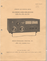
Hook the snap rings on the provided
lifting handle into the holes in the tabs
on either end of the transformer
HF-2500 EXPORT
Transformer Installation
Position the transformer over the mounting holes
in the chassis and insert the four provided 1/4-20
Phillips head screws through the transformer
mounting tabs and into the threaded inserts in the
chassis plate and tighten.
Here is the lifting handle attached and
ready for use.
The transformer is HEAVY, so carefully
lift it into place in the chassis. BE CARE-
FUL NOT TO BUMP THE PC BOARD
ON THE BACKS OF THE METERS.

7
Plug the second connector on the transformer
into the mating one that comes from the AC
control board. It is keyed so that it cannot be
plugged in backwards. Make sure that the
connector halves are pressed together until the
lock tabs snap in place.
This completes HF-2500 EXPORT
transformer installation.
Plug the first connector on the transformer into
the mating one on the chassis wiring harness. It
is keyed so that it cannot be plugged in back-
wards. Make sure that the connector halves are
pressed together until the lock tabs snap in place.
Dress the wires and connectors down out of
the way as shown.
View of the completed transformer installa-
tion

8
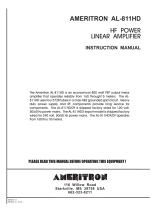
Connecting Your Amplifier
• Connect the RF output of your transceiver to the RF Input connector on the rear of the HF-
2500 EXPORT with 50 Ohm coaxial cable.
• Connect the existing station antenna tuner or a Wattmeter and dummy load to the RF Output
connector on the HF-2500 EXPORT with RG-8 or better coaxial cable.
• Connect the Keyline jack on the rear of the HF-2500 EXPORT to the normally open terminal
of the relay jack on your transceiver. The Key jack on the HF-2500 EXPORT has positive 5
VDC open circuit and requires the sinking of 15 mA of current when pulled to ground.
• Connect as short a ground lead as possible from a good RF ground to the Ground Post on
the HF-2500 EXPORT.
• Connect the ALC phono jack to the ALC connection on your transceiver using a shielded
cable. Consult your transceiver manual for proper ALC connection details.
Key
ALC
RF Ouput
RF Input
RF Output
Ground
Antenna
Tuner
Ground
To Earth
Ground
ALC TX GND
To Antenna
Transceiver
HF-2500 Export Amplifier
Wattmeter
To
Dummy
Load

9
Rear Panel View
Tuned Input
Adjustments
(One for each
band)
Automatic Level
Control Adjust
RF Output
(to Wattmeter
& Antenna
or Antenna
Tuner)
RF Input
(from
Transceiver)
Ground
Post
Key Line
(to transceiver)
ALC
(to transceiver)
AC Mains
Twistlock
Connector
AC Power Twistlock Connector Wiring
(View looking at rear panel)
GREEN
BLACK
}
WHITE
To Safety Ground
To 200/234VAC @ 30A
X
Y
G

10
TUNING PROCEDURE
Set the front panel controls to the following positions:
ON - OFF Switch. OFF
STANDBY - OPERATE STANDBY
BAND SWITCH DESIRED BAND
TUNE CONTROL PRESET TUNE SETTINGS (See test sheet)
LOAD CONTROL PRESET LOAD SETTINGS (See test sheet)
After the controls have been preset and the amplifier is connected to a suitable RF load,
switch the On/Off switch to the On position. The following will occur:
A. The meters will illuminate.
B. The step-start relay will actuate and the HV will begin to ramp up.
C. After 2 seconds the step-start relay will disengage and the HV will now be at its normal
no-load voltage level.
D. The 3 minute filament timer will start. The green “Status-Trip” LED will flash (1Hz
rate) during the 3 minute warm-up interval.
E. After 3 minutes the “Status-Trip” LED stops flashing and the amplifier is ready for use.
Place the Standby/Operate switch in the Operate position. The amplifier will not switch to
the “Operate” state if the Keyline is active when the switch is thrown (this protects the amp in
Load Control Standby/Operate
Switch
Power
On/Off
Band Switch Tune Control Transmit
Indicator
LED
Status-Trip
Indicator
LED
Plate Current/
Plate Voltage
Meter
Grid Current/
Relative Power
Meter

11
case it is inadvertently keyed when the switch is thrown). Key the exciter with no RF drive ap-
plied. The red transmit LED should illuminate, and the meter should indicate approximately
150 mA of plate current. Apply 5 to 10 watts of RF drive, the plate current should rise slightly.
If the plate current rises above 1800 mA, reduce drive. Adjust the TUNE control to peak the
grid current and achieve maximum output power as indicated on an external Wattmeter.. COM-
PLETE THESE ADJUSTMENTS AS QUICKLY AS POSSIBLE TO AVOID STRESSING
THE TUBES.
Adjust the LOAD control to reduce grid current while maintaining output power as indi-
cated on ther relative output meter or an external Wattmeter. Next, increase the drive in small
increments and adjust the LOAD control for maximum output while keeping the grid cur-
rent low. Under normal conditions the grid current should not exceed 60mA.
Readjust the TUNE control to again peak the reading on the grid meter. If the meter rises
above 150mA. quickly reduce drive and adjust the LOAD control counterclockwise to reduce
grid current. Repeat these adjustments as required to achieve the desired output up to 2800
Watts.
[NOTE: If the grid current is allowed to reach or exceed 180mA, the controller will imme-
diately un-key the amplifier and the “Status-Trip” LED will flash rapidly, indicating that a grid
current limit (a “Grid-Trip”) has occurred.
In order to reset the Grid-Trip circuitry, the exciter must be un-keyed and the “Standby-
Operate” switch must be switched to “Standby” and then back to “Operate.” Once the Grid-
Trip has been reset, the “Status-Trip” LED will stop flashing and remain illuminated.
Do NOT exceed 1800mA plate current.]
Note that when increasing output power the tune scale will always read higher and the load
will read lower. Also, the supplied inspection sheet has all of these settings and they should be
used as a guide for this procedure. If your settings vary widely from these you have something
wrong and should start over.
If your planned operation is on SSB, you should reduce the load control slightly counter-
clockwise, reducing the TOTAL output slightly about 30 to 50 Watts. This adjustment is neces-
sary to insure that the amplifier is sufficiently loaded to handle the plate current peaks caused
by the complex voice patterns during SSB operation. Nominal plate and grid current read-
ings during SSB operation will be about 30 to 40% of the key down CW readings.
CAUTION: THE TUNE AND LOAD AIR VARIABLE CAPACITORS MAY ARC IF
MAXIMUM DRIVE IS APPLIED BEFORE THE AMPLIFIER IS PROPERLY TUNED. AL-
WAYS FOLLOW THE DESCRIBED TUNE-UP PROCEDURE TO AVOID CAPACITOR
ARCING. ARCING MAY ALSO OCCUR IF YOU ATTEMPT TO TUNE INTO AN AN-
TENNA WITH A VSWR GREATER THAN 2:1.
Generally expect to tune by peaking grid current and
simultaneously dipping plate current.

12
Theory Of Operation
The Commander HF-2500 EXPORT uses three C.P.I. Eimac 3CPX800A7 pulse rated ce-
ramic/metal triodes in a class AB2 grounded grid configuration. Nominal drive power of 20 to
65 Watts.
This amplifier will operate on the following amateur bands: 160, 80, 40, 20, 15, 17, 12 and
10 meters.
Metering Functions
The Commander HF-2500 EXPORT has two illuminated cross-needle panel meters. The left-
hand meter continuously displays 3CPX800A7 grid current and relative output power. Under
typical operating conditions the grid current will be 20-60mA.
Plate voltage and Plate current are continuously displayed on the right-hand meter. The
typical plate current under nominal rated output (2800 Watts) should range from approximately
1000mA to 1800mA, with an absolute maximum of 1800mA.
Tuned Input Circuits and Adjustments
The tuned input circuits utilize an π impedance matching circuit with a high Q design.
These circuits employ RF phase compensating capacitors to reduce intermodulation products.
The use of mica trimmer capacitors allows adjustments to match the transceiver to the ampli-
fier. The rear panel provides easy access to these trimmer capacitors. A front panel band switch
selects the appropriate input filter.
Your Commander amplifier has mica trimmer capacitors which are easily accessed thru
holes located on the rear panel. The tuned input circuits are factory tuned and should not be re-
adjusted unless necessary. You can easily make adjustments for any change in your preference
for operating frequency range. Also, slight adjustments may be necessary because of slight vari-
ances in impedances between your transceiver and the tuned input circuitry of the amplifier.
1. Install a SWR meter between the transceiver and the amplifier.
2. Make sure the Standby/Operate switch is in the Operate position and the band switch
is set to the same band as the one for which you are making adjustments. Your ampli-
fier should also be properly tuned and loaded (preferably onto a dummy load of suffi-
cient capacity).
3. Apply drive, observe the SWR, and adjust the trimmer capacitor for minimum SWR.
Be careful not to overdrive the amplifier.
4. Repeat this procedure for each band.
Automatic Level Control and Adjustments
An adjustable Automatic Level Control (ALC) circuit limits the peak output power. When
properly set, this circuit insures that the amplifier can not be overdriven. Rear panel access al-
lows for easy manual adjustment. A sample of the RF input derives the ALC voltage.
Your transceiver's internal ALC will maintain linearity. The amplifier's ALC will prevent
overdriving the amplifier. The HF-2500 EXPORT’s ALC circuit was designed for negative going
ALC voltage. Proper adjustment is as follows:
1. Use an insulated tool when making these adjustments.
2. Tune the amplifier for operation on the 20 meter band for full 2800 watts output.
3. With your transceiver set for 20 meter SSB operation, set the transceiver's microphone

13
gain for normal operation as specified in its owners manual.
4. While speaking louder than normal into the microphone, adjust the ALC pot through the
access hole on the rear panel . Adjust for 2800 Watts maximum output as indicated on
an external peak reading Wattmeter.
5. On some newer model transceivers this adjustment can be made in the CW position. On
these models (with your output at 1500 Watts) simply adjust for a slight drop in output.
Output Filter Circuit
The π variable network filter transforms the plate load impedance from approximately 2500
Ohms down to 200 Ohms, Two air variable capacitors and an associated inductor accomplish
this transformation. A heavy duty band switch selects the proper inductance from high Q induc-
tors with appropriate taps for the desired band of operation.
A design Q of 14 allows for good harmonic attenuation on all bands. A special reactance-
tuned ferrite core 4 to 1 transmission line transformer steps down the 200 Ohm output of the π
circuit to the 50 Ohm nominal antenna impedance. This also provides further harmonic attenua-
tion of the output in the same manner as an L coil in a π-L network.
High Voltage Supply
The high voltage supply operates from 200/234 VAC, 30 Ampere line. The primary of the
high voltage transformer is switched on and off with relays and incorporates a step-start circuit
to limit in-rush current while the high voltage filter capacitors charge. The front panel On/Off
switch applies AC mains power to the controller circuitry which then controls AC power to the
filament and HV transformers. 2400 VAC from the transformer is applied to a full wave bridge
rectifier. Metering of the tube anode and grid current is accomplished by shunt resistors located
in the negative return of the 3CPX800-A7 cathode. Plate voltage metering is accomplished by a
resistor divider network in the B+ line of the high voltage circuit.

14
Limited Warranty
Palstar Inc. warrants the Commander HF-2500 EXPORT to be free from defects in material
and workmanship under normal use and service to the original buyer for a period of one (1)
year from the date of delivery to that buyer (the “Warranty Period”). Palstar Inc.’s obligation
under this warranty is limited to repair or replacement of the product at it’s option at the Palstar
factory in Piqua, OH.
This warranty is effective only when the product is returned to the factory with all transpor-
tation charges prepaid and examination of the product discloses the product, in Palstar’s judg-
ment, to have been defective during the Warranty Period.
The Warranty Period shall not extend beyond its original term with respect to interim in-
warranty repairs by Palstar. This Warranty Period shall not apply to any product which has been
repaired or altered by anyone other than Palstar without prior written authorization. Warranty
does not extend to any products which have been subject to damage from improper installation,
application or maintenance in accordance with the operating specifications. Palstar neither as-
sumes nor authorizes any person to assume for it any obligation or liability other than herein
stated.
Shipping Your Amplifier Back to the Factory
Due to the necessity of shipping the amplifier with the HV transformer removed, please
contact the factory for instructions before sending an amplifier back to us. There are circum-
stances in which it may not be necessary to return the HV transformer, thereby saving you ship-
ping charges. When you call, Palstar will inform you if transformer return is necessary. If
transformer return is necessary, remove it from the amplifier cabinet and ship it separately, and
must be in its original packing.
Repair Policy
When sending in a product for service, see the section above. If not using the original pack-
ing materials, please “double” box it carefully with suitable padding and ship it insured for your
protection. Please include a note clearly describing the problem, how you wish the item re-
turned and how you wish to pay for the service. Package your unit properly. Palstar, Inc. is not
responsible for merchandise damaged in shipment. Our service rate is $30 per hour (1/2 hr.
minimum).
Return Policy
All returns must receive prior authorization from Palstar. Returned items must be received
in original—AS SHIPPED—condition including the original box, manuals, accessories, and
copy of sales receipt. Returns must be within 14 days of purchase. Returned items are subject to
a 25% restocking fee. Shipping is not refundable.

15
Specifications
COMMANDER HF-2500 EXPORT
HF Linear Power Amplifier
• Band Coverage: 160, 80, 40, 20, 17, 15, 12, and 10 meter amateur radio bands.
• Types of Emissions: SSB, FM, CW, AM, RTTY, SSTV.
• Driving Power Required: 20 to 90 Watts nominal at rated continuous carrier output.
• Maximum Output Power: 2800 Watts Continuous Carrier.
• Duty Cycle: 50 percent in Amateur service at 2800 watts output power
• Input impedance: 50 Ohm unbalanced
• Output Impedance: 50 Ohm unbalanced: SWR 2:1 or less
• Harmonic Suppression: Exceeds all FCC requirements
• Keying: Requires contact closure capable of sinking +5 VDC at 15 mA
• Metering: Plate voltage, plate current, grid current, and relative power
• A.L.C.: Negative going, adjustable from rear panel
• Front Panel Controls: On/Off switch; Standby/Operate switch; Tune; Load; Band selector
switch.
• Rear Panel Controls: Tuned input adjustment; ALC adjustment; RF input; RF output;
ALC output; Keying; ground connection; AC power inlet.
• Tube Complement: Three Eimac 3CPX800A7 pulse rated ceramic/metal triodes.
• Cabinet Size: 18.25" W x 8.5" H x 20.75" D (46.3cm x 21.6 cm x 52.7 cm)
• Weight: 120lbs. ( 54.6 kg. ) (including transformer)
• Power Requirement: 200/234 VAC, 50/60 Hz, 30 Amperes

16
HF-2500 Export TOP VIEW

17
Bottom View showing access plate
HV Power Supply PCB Cathode and Filament Interface PCB
Access Plate Removed

18
HF-2500 EXPORT HV Power Supply

19
AC Mains and Step-Start Board
/862-118

20
Control and Metering Board
/