Page is loading ...

UK
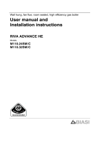
MURELLE EV HE
25/55 - 30/55
Installation and
servicing instructions
PLEASE LEAVE THIS INSTRUCTION
WITH THE USER

All descriptions and illustrations provided in this manual have been carefully prepared but we reserve the right to make changes
and improvements in our products that may affect the accuracy of the information contained in this manual.
This boiler may require 2 or more operatives to move it into its installation site, remove it from its packaging and during
movement into its installation location. Manoeuvring the boiler may include the use of a sack truck and involve lifting pushing
and pulling.
Caution should be exercised during these operations.
Operatives should be knowledgeable in handling techniques when performing these tasks and the following precautions
should be considered:
– Grip the boiler at the base
– Be physically capable
– Use personal protective equipment as appropriate e.g. gloves, safety footwear.
During all manoeuvres and handling actions, every attempt should be made to ensure the following unless unavoidable
and/or the weight is light.
– Keep back straight
– Avoid twisting at the waist
– Always grip with the palm of the hand
– Keep load as close to the body as possible
– Always use assistance
WARNING
Caution should be exercised when performing any work on this appliance.
Protective gloves and safety glasses are recommended.
– Avoid direct contact with sharp edges.
– Avoid contact with any hot surfaces.
NOTICE
Please be aware that due to the wet testing of the appliance, there may some residual water in the hydraulic circuit.
– Protect any surfaces, carpets or floorings.
– Use a suitable container to catch any water that escape when removing the protective caps from the connections.
SAFE HANDLING


The Benchmark Scheme
Sime Ltd is a licensed member of the Benchmark Scheme which aims to improve the standards of installation and
commissioning of domestic heating and hot water systems in the UK and to encourage regular servicing to optimi-
se safety, efficiency and performance.
Benchmark is managed and promoted by the Heating and Hotwater Industry Council.
For more information visit www
.centralheating.co.uk

IMPORTANT
When carrying out commissioning of the boiler, you are highly recommended to perform the following checks:
–
Make sure that there are no liquids or inflammable materials in the immediate vicinity of the boiler.
– Make sure that the electrical connections have been made correctly and that the earth wire is connected to a
good earthing system.
– Open the gas tap and check the soundness of the connections, including that of the burner.
– Make sure that the boiler is set for operation for the type of gas supplied.
– Check that the flue pipe for the outlet of the products of the combustion is unobstructed and has been properly
installed.
– Make sure that any shutoff valves are open.
– Make sure that the system is charged with water and is thoroughly vented.
– Check that the circulating pump is not jammed (CAUTION: protect the control panel from any water lost from the
pump.
– Purge the system, bleeding off the air present in the gas pipe by operating the pressure relief valve on the gas
valve inlet.
– Ensure that all the controls and safety devices have been demonstrated to the user.
– Ensure that all the manuals and documentation that are supplied with the boiler are left with the user.
CONTENTS
1 DESCRIPTION OF THE BOILER . . . . . . . . . . . . . . . . . . . . . . . . . . . . . . . . . . . . . . . . . . . . . . . . . . . . . . . . . . . . . . . pag. 6
2 INSTALLATION . . . . . . . . . . . . . . . . . . . . . . . . . . . . . . . . . . . . . . . . . . . . . . . . . . . . . . . . . . . . . . . . . . . . . . . . . . . . . . pag. 10
3 CHARACTERISTICS . . . . . . . . . . . . . . . . . . . . . . . . . . . . . . . . . . . . . . . . . . . . . . . . . . . . . . . . . . . . . . . . . . . . . . . . . . pag. 22
4 USE COMMISSIONING, AND MAINTENANCE
(including BENCHMARK/Mains Pressure Hot Water Storage Checklist & Service Record) . . . . . . pag. 27
5 FAULT FINDING . . . . . . . . . . . . . . . . . . . . . . . . . . . . . . . . . . . . . . . . . . . . . . . . . . . . . . . . . . . . . . . . . . . . . . . . . . . . . pag. 37
6 REPLACEMENT OF PARTS . . . . . . . . . . . . . . . . . . . . . . . . . . . . . . . . . . . . . . . . . . . . . . . . . . . . . . . . . . . . . . . . . . . pag. 38
7 EXPLODED VIEWS . . . . . . . . . . . . . . . . . . . . . . . . . . . . . . . . . . . . . . . . . . . . . . . . . . . . . . . . . . . . . . . . . . . . . . . . . . pag. 40
Murelle EV HE 25/55: Gas Council number 47-283-20
Murelle EV HE 30/55: Gas Council number 47-283-21
IPX4D
Important Information
IT IS A STATUTORY REQUIREMENT THAT ALL GAS APPLIANCES ARE INSTALLED BY COMPETENT PERSONS,
IN ACCORDANCE WITH THE GAS SAFETY (INSTALLATION AND USE) REGULATIONS (CURRENT EDITION). The
manufacturer’s instructions must not be taken as overriding any statutory requirements, and failure to com-
ply with these regulations may lead to prosecution.
No modifications to the appliance should be made unless they are fully approved by the manufacturer.
GAS LEAKS: DO NOT OPERATE ANY ELECTRICAL SWITCH, OR USE A NAKED FLAME. TURN OFF THE GAS
SUPPLY AND VENTILATE THE AREA BY OPENING DOORS AND WINDOWS CONTACT THE GAS EMERGENCY
SERVICE ON 0800111999.
Please refer to commissioning instructions for filling in the checklist of this installation guide.
Note: All Gas Safe registered installers carry a ID Card.
You can check your installer is Gas Safe Registered by calling 0800 408 5577

6
1.1 INTRODUCTION
MURELLE EV HE 25-30/55 are premixed
gas condensation thermal modules that
employ a microprocessor-based technology
to control and manage all the functions. All
modules are compliant with European
Directives 2009/142/CE,
2004/108/CE, 2006/95/CE and
92/42/CE. For optimum installation and
operation, always follow the instructions
provided in this manual.
The products manufactured and sold by
Sime do not contain any banned materials
or substances (ie they comply with
ISO9000:2000).
1.2 UNPACK AND CHECK THE
CONTENTS, AND PACKAGING
REMOVAL.
1.2.1 Handling the boiler
Due to the weight of the boiler, take care to
avoid personal injury or damage.
1.2.2 Storage Prior to installation
The boiler must be stored horizontally on
its pallet prior to installation.
Do not stack more than six units.
1.2.3 Unpacking the boiler
The boiler is supplied fully assembled, the
kit includes :
- boiler
- valve pack
- guarantee
- these Installation/Users instructions
- wall mounting template.
Remove the strapping and carefully remove
the carton and packaging.
Check the contents, instructions, valve
pack, and hanging bracket.
Remove the two bolts securing the boiler to
the pallet.
1 DESCRIPTION OF THE BOILER
100
15 2
100
70
78
EU MRG
E
U
C
S3
MR
G
245
288
15 6
L
460
190
80
85
110
90
ø 60/100
950
400
955
470
600
Fig. 1
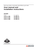
1.3 DIMENSIONS
L (mm)
Murelle EV HE 25/55 286
Murelle EV HE 30/55 222
SERVICE CLEARANCES
ABOVE THE APPLIANCE CASING 300 mm
AT THE R.H.S. 20 mm
AT THE L.H.S. 20 mm
BELOW THE APPLIANCE CASING 400 mm
IN FRONT OF THE APPLIANCE 500 mm
CONNECTIONS
R C.H. return 22 mm Compression
M C.H. flow 22 mm Compression
G Gas connection 15 mm Compression
E D.H.W. inlet 22 mm Compression
U D.H.W. outlet 15 mm Compression
C Ricirculation 15 mm Compression
S3 Condensation outlet ø 20

7
Models 25/55 30/55
Heat output
Nominal (80-60°C) kW 23.9 28.9
Nominal (50-30°C) kW 26.2 31.6
Reduced G20 (80-60°C) kW 6.1 7.6
Reduced G20 (50-30°C) kW 7.0 8.5
Reduced G31 (80-60°C) kW 7.5 8.7
Reduced G31 (50-30°C) kW 8.5 9.6
Heat input
Nominal kW 24.5 29.5
Reduced G20/G31 kW 6.5/8.0 8.0/9.0
Max/min useful yield (80-60°C) % 94/97.5 95/98
Max/min useful yield (50-30°C) % 107/107 107/107
Useful yield at 30% of the load (50-30°C) %107 107
Termal efficiency (CEE 92/42 directive)
Losses after shutdown to 50°C (EN 483) W/h 90 95
Supply voltage V-Hz 230-50 230-50
Adsorbed power consumption W115 115
Electrical protection grade IP X4D X4D
C.H. setting range °C 20/80 20/80
Water content boiler l 9.6 10
Maximum water head bar 3 3
Maximum temperature °C 85 85
Capacity/pressure of the heating expansion vessel l/bar 10/1 10/1
Normal operating pressure of the system (max) bar 5.5 5.5
D.H.W. setting range °C 30/60 30/60
D.H.W. flow rate (EN 625) l/min 15.5 17.5
Continuous D.H.W. flow rate ∆t 30°C l/min 11.4 13.8
Continuous D.H.W. flow rate ∆t 35°C l/min 9.8 11.8
D.H.W pressure min/max bar 0.2/5.5 0.2/5.5
D.H.W. tank capacity l51 51
Recuperation time between 15 and 60°C min 9’ 55” 10’ 10”
Recuperation heat of 70% contents min 3’ 40” 3’ 30”
D.H.W. expansion vessel capacity / charge pressure l/bar 2.5/3.0 2.5/3.0
Exhaust fumes temperature at max flow rate (80-60°C) °C 70 70
Exhaust fumes temperature at min. flow rate (80-60°C) °C 65 65
Exhaust fumes temperature at max flow rate (50-30°C) °C 40 40
Exhaust fumes temperature at min. flow rate (50-30°C) °C 35 35
Smokes flow min/max kg/h 12/42 14/50
CO
2 at max/min flow rate G20 - G31 % 9.0/9.0 - 10.0/10.0 9.0/9.0 - 10.0/10.0
CE certification n° 1312BS5039 1312BS5039
Category II2H3P II2H3P
Type B23P-53P/C13-33-43-53-83 B23P-53P/C13-33-43-53-83
NOx emission class 5 (< 70 mg/kWh) 5 (< 70 mg/kWh)
Weight when empty kg 68 70
Main burner nozzle
Quantity nozzles n° 1 1
G20/G31 nozzle diameter ø 6.0/4.4 6.0/4.4
Consumption at maximum/minimum flow rate
G20 m
3
/h 2.59/0.53 3.12/0.66
G31 kg/h 1.90/0.62 2.29/0.62
Gas supply pressure
G20/G31 mbar 20/37 20/37
1.4 TECHNICAL FEATURES

8
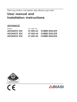
1.5 FUNCTIONAL DIAGRAM
Fig. 2
KEY
1 Fan
2 Air/gas mixer
3 Primary exchanger
4 Limit stat
5 Air relief valve
6 Safety thermostat 100°C
7 C.H. sensor (SM)
8 Flow switch
9 C.H. Expansion vessel
10 D.H.W. tank
11 TPR valve 7 BAR 90°C -TPRV
12 Magnesium anode
13 D.H.W. sensor (SB)
14 C.H. Safety valve 3 BAR
15 Gas valve
16 Pump
17 Diverter valve
18 Auto air vent
19 D.H.W. expansion vessel
20 Water pressure transducer
21 Automatic bypass
23 D.H.W. drain cock
24 Condensate drain tap
25 Gas cock
26 Heating system return cock
27 Heating system delivery cock
30 Pressure reducing valve 3.5 BAR
31 Non-return valve
32 Expansion relief valve 6 BAR
33 Tundish expansion relief valve
34 Filling loop
35 Tundish
36 D.H.W. safety limit stat 85°C
CONNECTIONS
R C.H. return
M C.H. flow
G Gas connection
E D.H.W. inlet
U D.H.W. outlet
C Recirculation
S3 Condensation outlet

9
Fig. 3
1.6 MAIN COMPONENTS
KEY
1 Control panel
2 Pump
3 Gas valve
4 Flow switch
5 C.H. sensor (SM)
6 Condensate drain tap
7Fan
8 Ionisation electrode
9 Ignition electrode
10 Primary heat exchanger
11 Exhaust fumes sensor (SF)
12 Auto air vent
13 Limit stat 90°C
14 Ignition transformer
15 D.H.W. combined temperature
and pressure relief valve
16 Expansion vessel
17 Safety thermostat 100°C
18 D.H.W. sensor (SB)
19 D.H.W. tank
20 D.H.W. expansion vessel
21 Tundish
22 C.H. safety valve 3 BAR
23 D.H.W. safety limit stat 85°C

10
Where no specific instructions are given,
the installation should be in accordance
with the relevant recommendations in the
current editions of the following British
Standards and Codes of Practice: BS
5440-1, BS 5440-2, BS 5449, BS 5482
(propane installations), BS 5546, BS 6700,
BS 6798, BS 6891, Institute of Gas Engi-
neer document IGE/UP-7, BS 7074 (expan-
sion vessel), and to other relevant British
Standards or code of Practice as neces-
sary. It is a Statutory Requirement that
the installation conforms to the appropria-
te Building Regulations either The Building
Regulations, The Building Regulations (Sco-
tland), Building Regulations (Northern Ire-
land), the Water Fitting Regulations or
Water Byelaws in Scotland, and the cur-
rent I.E.E Wiring Regulations. When hand-
ling, due consideration should be given to
the appliance weight. If the appliance is not
to be installed immediately it should be sto-
red in a clean dry place.
2.1 VENTILATION REQUIREMENTS
Detailled recommendations for air supply
are given in BS5440:2. The following notes
are for general guidance:
– It is not necessary to have a purpose
provided air vent in the room or com-
partment in which the appliance is
installed. However, suitable clearances
for maintenance and servicing should
be provided, see fig. 1.
2.1.1 Anti-freeze function
The boilers are equipped with anti-freeze
function which activates the pump and the
burner when the temperature of the water
contained inside the appliance drops to
below 6°C. The anti-freeze function is ensu-
red, however, only if:
- the boiler is correctly connected to the
gas and electricity supply circuits;
- the boiler is turned on;
- the boiler ignition is not locked out;
- the essential components of the boiler
are all in working order.
In these conditions the boiler is protected
against frost down to an environmental
temperature of -5°C.
ATTENTION: In the case of installation in a
place where the temperature drops below
0°C, the connection pipes must be protected.
2.2 BOILER SUPPORT BRACKET
Ensure that the wall on which the boiler is to
be mounted is capable of supporting the
weight of the boiler when filled (123 kg -
25/55 and 125 kg - 30/55)
- Position the bracket ensuring that the boi-
ler is fitted with sufficient clearance to
allow for the fitting of the valve connec-
tions.
- Fix the bracket level and with fixings capa-
ble of supporting the weight.
- Hang the boiler and then tighten the
screws indicated in fig 4.
2.3 HOW TO FIT C.H. AND D.H.W.
FITTINGS AND GAS COCK (fig. 5)
– C.H. CONNECTIONS (R & M)
F
it the two isolation valves (10) using the
gasket supplied (6). Fit the C.H. filling
loop between the C.H and D.H.W. cir-
cuits, ensuring the correct position and
orientation of the isolation valves.
– D.H.W. CONNECTION (E & U)
Fit the supplied; pressure reducing valve
(17), check valve (16), and expansion
relief valve assembly (14) with its associ-
ated tundish (15), ensure that on com-
pletion of the installation that the tun
dish is visible to the user, in the D.H.W.
supply to the appliance, the flow from
this assembly should be connected to
the cold water inlet (E) via the flow regu-
lator housing supplied. Ensure flow regu-
lator (11) and gasket (1) supplied, are fit-
ted in the flow regulator housing.
See fig. 5 and fig. 6 for installation
details. It is important that no isolating
valve is fitted between the expansion
relief valve and the inlet to the D.H.W.
tank. Any additional D.H.W. drain down
tap fitted should be positioned as low as
possible to ensure that at least 80% of
the D.H.W. tank’s capacity can be
drained.
If installed in a Hard Water area, then a
suitable device should be fitted to treat
the mains supply to the appliance (Con-
tact your Water Distribution Company
for advice on suitable devices). Fit the
quarter bend (2) to the hot water outlet
(U) using the gasket supplied (1).
– GAS CONNECTION (C)
Fit the gas cock (12) to the gas connec-
tion (R) using the gasket supplied (6).
2.4 WATER SYSTEMS - GENERAL
This appliance is designed for connection to
sealed central heating water systems.
Check that the mains water flow is sufficient
to produce the required DHW flow rate but
does not exceed 4 bar pressure.
A expansion relief valve is incorporated
within the valve kit. Inlet safety kit and all
safety devices must be installed.
F
or balanced pressures in premises
For balanced pressure to the whole pre-
mises an additional pressure reducing
valve should be installed at the inlet to the
premises set at 3.5 BAR.
The maximum water supply pressures to
the pressure reducing must be no more
than 16 BAR.
2.4.1 Treatment of Water
Circulating Systems
– All recirculatory systems will be subject
to corrosion unless an appropriate
water treatment is applied. This means
that the efficiency of the system will
deteriorate as corrosion sludge accu-
mulates within the system, risking dam-
age to pump and valves, boiler noise and
circulation problems.
– For optimum performance after installa-
tion this boiler and its associated central
heating system must be flushed in
accordance with the guidelines given in
BS 7593 “Treatment of water in domes-
tic hot water central heating systems”.
– Sime Ltd recommend only the use of
FERNOX products for the flushing and
final treatment of the system water.
This is particularly important in hard
water areas. Artificially softened water
must not be used to fill the heating sys-
tem.
Failure to flush and add inhibitor to the
system may invalidate the appliance
warranty.
– It is important to check the inhibitor con-
centration after installation, system
modification and at every service in
accordance with the manufacturer’s
instructions.
(Test kits are available from inhibitor
stockists).
2.4.2 Requirements for
sealed water systems
The heating system design should be based
on the following information:
a) The available pump head is given in fig.
2 INSTALLATION
Fig. 4

11
20.
b) The burner starts when the C.H. flow
reaches 400÷450 l/h. This safety con-
dition is ensured by the flow switch.
c) The appliance is equipped with an inter-
nal by-pass that operates with system
heads (H) greater than 3 m.
The maximum flow through the by-pass
is about 300 l/h. If thermostatic radia-
tor valves are to be installed, at least
one radiator should be without a ther-
mostatic valve (usually the bathroom
radiator).
d) A sealed system must only be filled by a
competent person using the filling loop
as shown in fig 5.
e) To fill the cylinder, open a DHW tap,
then turn on the domestic water supply.
When water runs from the tap turn it
off. Repeat at each DHW tap.
NOTE: there should be no isolation valve
fitted between the cylinder and the
expansion valve.
f) To drain the cylinder see fig. 2 number
23.
2.4.3 Discharge Pipes and fittings
The position of any tundish must be visible
to the occupants and any tundish, drain
valve and discharge pipe and must be sited
away from any electrical components.
The 7 and 3 bar PRV's are called out with
the number 15 and 22 on fig. 3.
The connections to the expansion relief
valve and temperature and pressure relief
valve should not be used for any other pur-
pose. See fig. 6 for example of the dischar-
ge pipe(s) for the temperature and pressu-
re relief valve, and expansion relief valve
terminations.
9
8
10
9
8
10
6
R
M
6
S3
18
19
1
E
11
G
6
12
21
22
ø15
DS3
1
20
U
DS7
R
M
U
E
15
14
17
16
Fig. 5
KEY
1 Gasket ø 11,5/18,5 x 2
6 Gasket ø 17/24 x 2
8 Brass olive for 22 mm pipe
9 Locking nut 1-1/8”
10 Cock 3/4”
11 Flow regulator
12
Gas cock
13 Filling loop
14 Expansion relief valve
15 Tundish expansion relief valve
16 Single check valve
17 Pressure reducing valve
18 Curve return system
19 Curve flow system
20 D.H.W. outlet pipe
21 Brass olive for 15 mm pipe
22 Locking nut 1/2”
CONNECTIONS
G Gas inlet
M C.H. flow
R C.H. return
U D.H.W. outlet
E D.H.W. inlet
S3 Condensation outlet
DS 3 3 bar discharge
DS 7 7 bar discharge
DS 3
DS 7
No isolation valve should be fitted
between the cylinder and the
expansion valve.

12
Note: it is permitted to connect dischar-
ge pipes together provided that the joint
pipe is sized to accommodate the combi-
ned flow.
2.4.4 Expansion Vessel (C.H. only)
C.H. EXPANSION VESSEL – The integral
expansion vessel is pre-charged to a pres-
sure of 1.0 bar, which should be checked
before the C.H. water system is filled.
This vessel is suitable for correct operation
of system capacities up to 82 litre capacity.
If the actual C.H. system volume is greater,
then an additional vessel must be fitted to
the system. For systems where the volume
is greater, the additional expansion vessel
volume can be determined by multiplying
the volume in excess of that which can be
accommodated by the appliance by the fac-
tor 0.901. BS 7074 gives further details
regarding C.H. expansion vessel sizing.
2.4.5 Connection of condensation
water trap
The drip board and its water trap must be
connected to a civil drain through a pipe
with a slope of at least 5 mm per metre to
ensure drainage of condensation water.
The plastic pipes normally used for civil
drains are the only type of pipe which is
appropriate for conveying condensation
to the building’s sewer pipes.
Fig. 6
Fig. 7
LIST OF ø 60/100 ACCESSORIES
1a-b
Coaxial duct kit L. 790 code 8096250
2a Extension L. 1000 code 8096150
2b Extension L. 500 code 8096151
3 Vertical adaptor code 8086950
C33
6
5
3
2
H (m)
C13
1
2
1
L (m)
IMPORTANT:
- The insertion of each additional 90° bend with a diameter of 60/100 (code
8095850) reduces the available section by 1.5 meters.
- The insertion of each additional 90° bend with a diameter of 80/125 (code
8095870) reduces the available section by 2 meters.
- Each additional 45° curve installed a diameter of 60/100 (code 8095950) the
80/125 (code 8095970) reduces the available length by 1.0 metres.
- During assembly it is important to make sure that the kit with axial pipes (1) is
positioned HORIZONTAL FLUES MUST BE LEVEL..
NOTE: Before connecting accessories, it is always advisable to lubricate the internal
part of the gaskets with silicon products. Avoid using oils and greases.
Model Length of pipe Length of pipe
ø 60/100 ø 80/125
HV HV
Min Max Min Max
25/55 6 m 1.3 m 8 m 12 m 1.2 m 15 m
30/55 5 m 1.3 m 7 m 10 m 1.2 m 13 m
LIST OF ø 80/125 ACCESSORIES
1a-b Coaxial duct kit L. 785 code 8096253
2a Extension L. 1000 code 8096171
2b Extension L. 500 code 8096170
3 Adapter for ø 80/125 code 8093150
5 Articulated tile 8091300
6 Roof Terminal 8091205
V (VERTICAL - m)
H (HORIZONTAL - m)

2.4.6 Dealing with condensate (fig.6/a)
Five suitable drainage points
Five suitable drainage points:
1. Internal drain stack pipe
2. Waste water pipe*
3. External drain or gully
*
4. Rainwater hoppers that carry both rain
water and foul water*
5. Purpose-made soakaways
* Care should be taken not to contaminate
any “Grey Water Systems”
Pipework
Condensate pipework should be plastic,
same as used for standard wastewater
plumbing.
Similarly the drainage system where the
condensate discharges to should also be
resistant to the acid condensate.
Pipework should be kept as short as possi-
ble. External runs should be avoided, but
when necessary be a minimum of 3 meter
in 32 mm diameter pipework and lagged to
avoid freezing, this also applies to pipe runs
in unheated areas such as garages.
To reduce the possibility of condensate
being trapped in the pipe, the number of
bends should be kept to a minimum.
Pipework must be angled down from the
boiler with a fall of at least 2.5°.
The pipework must be supported at a dis-
tance of 0.5 m for inclined runs and 1.0 m
for vertical runs.
Condensate traps
Where the condensate drain is not sealed
to the discharge connection a trap will be
required. The water seal should be 38 mm
or more for external discharge and 75 mm
or more for internal discharge. When con-
necting to a external stack the trap should
be located within the building.
Stack pipes
Condensate connections should be at least
450 mm above any bend at the bottom of a
stack pipe in a single or multi-story dwelling
up to 3 storeys. There are specific require-
ments when connecting to a stack pipe
serving multi-storey buildings greater than
3 storeys.
All connections to stack pipes should avoid
across flow between other Branch pipes.
Soakaways
Any soakaways have to be purpose-made
and located as close to the boiler as possi-
ble, but clear of the buildings foundations
and any buried services. The best option is
to purchase a soakaway from a drainage
manufacturer and install it to the manufac-
turers recommendation.
Condensate disposal
positioning and ter-
mination of the condensate drain pipe
The condensate pipe should run and termi-
nate internally to the house soil and vent
stack or waste pipe. Alternatively, the con-
densate can be discharged into the rainwa-
ter system, or into a purpose-made soak
away (condensate absorption point).
An alternative condensate waste pipe
should be considered where the system
could be effected by extreme weather con-
ditions.
All connecting drainage pipework should
have a fall of at least 2.5° to the horizontal,
or approximately 50 mm per metre of pipe
run.
13
Pipe slope
>2
1
/
2
deg
Internal trap
>75mm
>110mm
(for 100mm stack)
> 450mm
(for up to 3 floors)
100mm Internal stack
Branch
pipe
SINK
Height above
sink >100mm
Internal trap
>75mm
Pipe slope
>2
1
/
2
deg
Height above
sink >100mm
SINK
> 1m
Section of plastic
drain pipe
Holes in side away
from dwelling
Ground level
Alternative
ground level
Limestone
chipping fill
Internal termination of condensate drainage pipe to internal stack
External termination of condensate
drainage pipe via internal discharge
branch (e.g. sink waste) and condensate
syphon
External termination of condensate
drainage pipe via internal discharge
branch (e.g. sink waste - proprietary
fitting) and condensate syphon
External termination of
condensate drainage
pipe to absorpion point
Fig. 6/a

14
163
67
286
211
166
222
336
15 6
130
67
CA
CA
CS
CA
CA
CS
25/55
30/55
115
190
ø 80
ø 60
2.4.7 Filter on the gas pipe
The gas valve is supplied ex factory with an
inlet filter, which, however, is not adequate
to entrap all the impurities in the gas or in
gas main pipes.
To prevent malfunctioning of the valve, or in
certain cases even to cut out the safety
device with which the valve is equipped,
install an adequate filter on the gas pipe.
2.4.8 Discharge Pipe
See fig. 6 for example discharge pipe termi-
nations.
2.5 INSTALLATION OF COAXIAL DUCT
(ø 60/100 - ø 80/125)
The axial suction and discharge pipes are
supplied in a special kit (that can be purcha-
sed separately) along with assembly
instructions. The diagrams of fig. 7 illustra-
te some examples of different types of
discharge modalities allowed and the maxi-
mum lengths that can be reached.
2.6 INSTALLATION OF SEPARATE
DUCTS (ø 80)
Separate duct kit code 8089911 is used to
connect twin 80mm pipes. See fig 8.
The maximum overall length of the flue is
determined by the head losses of the indivi-
dual components and must not exceed
15mm H2O. Additionally the length of either
the inlet or exhaust pipe must not exceed
50 m. See Table 1 for information on the
load losses of single accessories and Fig. 9
for types of “smoke outlet”-”air inlet”.
2.6.1 Separate ducts kit
The diagrams of Figure 9 show a few exam-
ples of the permitted exhausts configura-
tions.
Fig. 8
TABLE 1 - ACCESSORIES ø 80
Accessories ø 80 Head loss (mm H
2
O)
25/55 30/55
Inlet Outlet Inlet Outlet
Coaxial duct kit -- -- -- --
90° elbow MF 0.20 0.25 0.25 0.30
45° elbow MF 0.15 0.15 0.20 0.20
Extension L. 1000 (horizontal) 0.15 0.15 0.20 0.20
Extension L. 1000 (vertical) 0.15 0.15 0.20 0.20
Wall terminal 0.10 0.25 0.10 0.35
Wall coaxial exhaust
*
Roof outlet terminal * 0.80 0.10 1.10 0.15
*
This loss includes the losses of the adaptor 8091401.
9
C
C33
11
10
3
1
1
3
3
7
3
12
12
12
LIST OF ø 80 ACCESSORIES
1 Coaxial duct kit code 8089911
2 Additional 90° MF curve code 8077450 (6 pz.)
3 a Extension L. 1000 code 8077351 (6 pz.)
3 b Extension L. 500 code 8077350 (6 pz.)
7 a Additional 45° MF curve code 8077451(6 pz.)
7 b Additional 90° MF curve code 8077450 (6 pz.)
9 Manifold, code 8091401
10 Articulated tile code 8091300
11 Roof terminal code 8091205
13 Union suction/exhaust code 8091401
14 Coaxial exhaust ø 80/125 L. 885 code 8096253A
NOTE
Before connecting accessories, it is always advisable to lubricate the internal part of
the gaskets with silicon grease. Horizontal terminals must be level.
Fig. 9
KEY
CA Inlet
CS Outlet
C13
3
2
3
1
14
12
13
12

15
2.7 POSITIONING
THE OUTLET TERMINALS
The outlet terminals for forced-draught
appliances may be located in the external
perimeter walls and roof of the building. To
provide some indications of possible solu-
tions, Table 2 gives the minimum distances
to be observed, with reference to the type
of building shown in fig. 9.
2.8 ELECTRICAL CONNECTION
The boiler is supplied with an electric cable.
Should this require replacement, it must be
purchased exclusively from SIME.
The electric power supply to the boiler must
be 230V - 50Hz single-phase through a
fused main switch, fused at 3 amps with at
least 3 mm spacing between contacts.
Respect the L and N polarities and the
earth connection.
NOTE: SIME declines all responsibility for
–If the terminal discharges into a pathway or passageway check that combustion prod-
ucts will not cause nuisance and that the terminal will not obstruct the passageway.
–Where the lowest part of the terminal is fitted less than 2 m (78 in) above ground,
above a balcony or above a flat roof to which people have access, the terminal MUST
be protected by a purpose designed guard.
–Where the terminal is fitted within 850 mm (34 in) of a plastic or painted gutter, or
450 mm (18 in) of painted eaves, an aluminium shield at least 1,500 mm (59 in) long
must be fitted to the underside of the painted surface.
–The air inlet/outlet flue duct MUST NOT be closer than 25 mm (1 in) to combustible
material.
–In certain weather conditions the terminal may emit a plume of steam. This is normal
but positions where this would cause a nuisance should be avoided.
Fig. 9
Terminal position Minimum spacing
A Directly below an openable window, air vent
or any other ventilation opening 300 mm 12 in
B Below guttering, drain pipes or soil pipes 75 mm 3 in
C/D Below eaves, balconies or carport roof (*) 200 mm 8 in
E From vertical drain pipes or soil pipes 75 mm 3 in
F From internal or external corners 300 mm 12 in
G Above adjacent ground, roof or balcony level 300 mm 12 in
H From a boundary or surface facing the boiler 600 mm 24 in
I From a terminal facing the terminal 1,200 mm 48 in
J From an opening in the carport
(eg door, window into dwelling) 1,200 mm 48 in
K Vertically from a terminal on the same wall 1,500 mm 60 in
L Horizontally from a terminal on the same wall 300 mm 12 in
M Horizontally from a vertical terminal to a wall 300 mm 12 in
N Horizontally from an openable window or other opening 300 mm 12 in
P Above an openable window or other opening 300 mm 12 in
Q From an adjacent vertical terminal 600 mm 24 in
TABLE 2
* this distance can be reduced to 25 mm provided surfaces are protected from the
effects of condensate

16
2.8.6 Use with different
electronic systems
Some examples are given below of boiler
systems combined with different electronic
systems. Where necessary, the parame-
ters to be set in the boiler are given.
The electrical connections to the boiler
refer to the wording on the diagram (fig.
11). The zone valve control starts at every
demand for heating of the zone 1 (it is from
part of the TA1 or the CR).
Description of the letters indicating the
components shown on the system dia-
grams:
M System output
R System return
CR Remote control CR 73
SE External temperature sensor
TA1-2-3-4 Zone room thermostat
CT1-2 Zone room thermostat
internal time clock
VZ1-2 Zone valve
RL1-2-3-4 Zone relay
Sl Hydraulic separator
P1-2-3-4 Zone pump
IP Floor system
EXP Expansion card Mixed Zone
(code 8092234)
VM Three-way mixer valve
R
M
SE
TA
CR
TA1
CR
SE
injury or damage to persons ,animals or
property, resulting from the failure to pro-
vide for proper earthing of the appliance.
2.8.1 Room Thermostat
The heat demand can by a "clean contact"
(conforming to EN607301), room stat or
programmer connected to the "TA" con-
nection ( fig 11) , CN6 terminals 7&8, after
removing the link.
Alternatively the heat demand can be by a
230v switched control, connected to ter-
minal 14 on connector CN7 and removal of
the TA link.
2.8.2 External Control CR 53
A CR 53 external control (part number
8092227),can be connected to the boiler.
This will control the heating function of the
boiler. The domestic hot water will continue
to be controlled by the boiler keypad.
NOTE: Reset parameter 10 to 2 (PAR 10
= 2).
2.8.3 Remote control CR 73
connection (optional)
The boiler is designed for connection to a
remote control unit, supplied on request
(code 8092226). The remote control unit
CR 73 allows for complete remote control
of the boiler, except reset.
The boiler display will show the following
message:
For installation and use of the remote con-
trol, follow the instructions in the package.
NOTE: Ensure PAR 10 set to 1 (PAR 10 =
1).
2.8.4 External sensor connection
The boiler is designed for connection to an
external temperature sensor, supplied on
request (code 8094101), which can auto-
matically regulate the temperature value of
the boiler output according to the external
temperature.
For installation, follow the instruction in the
package.
2.8.5 Remote RF control
The boiler is designed for connection to RF
remote controllers( mechanical - code
8092231 or digital - code 8092232),
which can control the central heating func-
tion.
1 BASIC SYSTEM
SYSTEM WITH A DIRECT ZONE AND ROOM THERMOSTAT, OR
WITH A CLIMATIC REGULATOR CR 53 (Code 8092227) OR WITH
REMOTE CONTROL CR 73 (Code 8092226) AND EXTERNAL SEN-
SOR (Code 8094101)
PARAMETERS SETTINGS
If using CR 53 set parameter 10 to 2
(PAR 10 = 2)

17
TA1
SE
R
M
SE
TA
VZ
TA1
VZ1
TA2
VZ2
R
M
SE
TA1
TA2
TA1
SE
TA
P2
RL
SI
RL1
RL2
P1
P
TA2
SE
R
M
SE
TA
VZ
TA1
VZ1
TA2
VZ2
CR
CR
2 BASIC SYSTEM
MULTI-ZONE SYSTEM WITH PUMP, ROOM THERMOSTAT AND EXTERNAL SENSOR (Code 8094101)
3 BASIC SYSTEM
MULTI-ZONE SYSTEM WITH PUMP, ROOM THERMOSTAT AND EXTERNAL SENSOR (Code 8094101)
4 BASIC SYSTEM
MULTI-ZONE SYSTEM WITH VALVE, ROOM THERMOSTAT, REMOTE CONTROL CR 73 (Code 8092226)
AND EXTERNAL SENSOR (Code 8094101)
PARAMETERS SETTINGS
To use the remote control
(CR) as remote control panel
for the boiler rather than as
room reference, set:
PAR 7 = 0

18
TA2
SE
R
M
SE
VZ
VZ1
TA2
VZ2
CR
CR
VZ1
TA1
PARAMETER SETTING
To use the remote control (CR) as room reference for a zone, set: PAR 7 = 1
Set the opening time of the zone valve VZ: PAR 33 = “OPENING TIME”
SI
R
M
SE
TA1
TA2
TA2
SE
TA
P2
RL
RL1
RL2
P1
P
CR
CR
PARAMETER SETTING
To use the remote control (CR) as room reference for a zone, set: PAR 7 = 1
5 BASIC SYSTEM
MULTI-ZONE SYSTEM WITH VALVE, ROOM THERMOSTAT, REMOTE CONTROL CR 73 (Code 8092226)
AND EXTERNAL SENSOR (Code 8094101)
6 BASIC SYSTEM
MULTI-ZONE SYSTEM WITH PUMP, ROOM THERMOSTAT, REMOTE CONTROL CR 73 (Code 8092226)
AND EXTERNAL SENSOR (Code 8094101)

19
R
M
SE
CT2
TA1
SE
CT1
SI
RL2
P2
P1
TA2
RL1
ZONA
GIORNO
(70°C)
ZONA
NOTTE
(50°C)
8 SYSTEM WITH DOUBLE TEMPERATURE OUTPUT
MULTI-ZONE SYSTEM WITH PUMP, ROOM THERMOSTAT INTERNAL TIME CLOCK AND EXTERNAL
SENSOR (Code 8094101)
R
M
SE
CT2
TA1
SE
CT1
TA2
VZ1
VZ2
ZONA
GIORNO
(70°C)
ZONA
NOTTE
(50°C)
DURING NIGHT TIME THE BOILER USES A LOWER OUTPUT TEMPERATURE IF DIFFERENT TIMES HAVE BEEN SET
FOR DAY AND NIGHT AREAS:
- with external sensor, set the climatic curve of the day zone 1 with PAR 25 and the night zone at PAR 26.
- without external sensor, gain access to setting the day zone 1 by pressing the key and change the value with
the keys and . Gain access to setting the night zone by pressing the key twice and changing the value
with the keys and
.
7 SYSTEM WITH DOUBLE TEMPERATURE OUTPUT
MULTI-ZONE SYSTEM WITH VALVE, ROOM THERMOSTAT INTERNAL TIME CLOCK AND EXTERNAL
SENSOR (Code 8094101)
DAY
ZONE
(70°C)
NIGHT
ZONE
(50°C)
DAY
ZONE
(70°C)
NIGHT
ZONE
(50°C)

20
R
M
SE
TA2
TA1
SE
TA1
SI
RL2
P2
P1
TA2
CR
CR
EXP
VM
EXP
IP
R
M
SE
TA3
TA1
SE
SI
RL3
P3
P2
TA2
IP
EXP
VM
EXP
IP
P4
TA4
RL4
TA1
TA2
11 SYSTEM WITH MIXER VALVE
SYSTEM WITH ONE DIRECT ZONE AND ONE MIXED ZONE
12 SYSTEM WITH MIXER VALVE
SYSTEM WITH TWO DIRECT ZONES AND TWO MIXED ZONES
PARAMETERS SETTINGS
To use the remote control
(CR) as remote control panel
for the boiler rather than as
room reference, set:
PAR 7 = 0
R
M
SE
TA1
SE
SI
P1
TA2
EXP
VM
EXP
IP
TA1
TA2
P2
VM
IP
EXP
13 SYSTEM WITH MIXER VALVE
SYSTEM WITH TWO MIXED ZONES INDEPENDENT AND TWO KITS ZONA MIX (Code 8092234)
/