
16 Port High Density KVM Switch
KH0116
User Manual
www.altusen.com

KH0116 User Manual
ii
FCC Information
This is an FCC Class A product. In a domestic environment this product may
cause radio interference in which case the user may be required to take
adequate measures.
This equipment has been tested and found to comply with the limits for a Class
A digital device, pursuant to Part 15 of the FCC Rules. These limits are
designed to provide reasonable protection against harmful interference when
the equipment is operated in a commercial environment. This equipment
generates, uses and can radiate radio frequency energy and, if not installed and
used in accordance with the instruction manual, may cause harmful
interference to radio communications. Operation of this equipment in a
residential area is likely to cause harmful interference in which case the user
will be required to correct the interference at his own expense.
RoHS
This product is RoHS compliant.

KH0116 User Manual
iii
User Notice
All information, documentation, and specifications contained in this manual
are subject to change without prior notification by the manufacturer. The
manufacturer makes no representations or warranties, either expressed or
implied, with respect to the contents hereof and specifically disclaims any
warranties as to merchantability or fitness for any particular purpose. Any of
the manufacturer's software described in this manual is sold or licensed `as is'.
Should the programs prove defective following their purchase, the buyer (and
not the manufacturer, its distributor, or its dealer), assumes the entire cost of all
necessary servicing, repair and any incidental or consequential damages
resulting from any defect in the software.
The manufacturer of this system is not responsible for any radio and/or TV
interference caused by unauthorized modifications to this device. It is the
responsibility of the user to correct such interference.
The manufacturer is not responsible for any damage incurred in the operation
of this system if the correct operational voltage setting was not selected prior
to operation. PLEASE VERIFY THAT THE VOLTAGE SETTING IS
CORRECT BEFORE USE.

KH0116 User Manual
iv
Safety Instructions
General
Read all of these instructions. Save them for future reference.
Follow all warnings and instructions marked on the device.
Do not place the device on any unstable surface (cart, stand, table, etc.). If
the device falls, serious damage will result.
Do not use the device near water.
Do not place the device near, or over, radiators or heat registers.
The device cabinet is provided with slots and openings to allow for
adequate ventilation. To ensure reliable operation, and to protect against
overheating, these openings must never be blocked or covered.
The device should never be placed on a soft surface (bed, sofa, rug, etc.) as
this will block its ventilation openings. Likewise, the device should not be
placed in a built in enclosure unless adequate ventilation has been
provided.
Never spill liquid of any kind on the device.
Unplug the device from the wall outlet before cleaning. Do not use liquid
or aerosol cleaners. Use a damp cloth for cleaning.
The device should be operated from the type of power source indicated on
the marking label. If you are not sure of the type of power available,
consult your dealer or local power company.
The device is equipped with a 3-wire grounding type plug. This is a safety
feature. If you are unable to insert the plug into the outlet, contact your
electrician to replace your obsolete outlet. Do not attempt to defeat the
purpose of the grounding-type plug. Always follow your local/national
wiring codes.
Do not allow anything to rest on the power cord or cables. Route the
power cord and cables so that they cannot be stepped on or tripped over.
If an extension cord is used with this device make sure that the total of the
ampere ratings of all products used on this cord does not exceed the
extension cord ampere rating. Make sure that the total of all products
plugged into the wall outlet does not exceed 15 amperes.
To help protect your system from sudden, transient increases and
decreases in electrical power, use a surge suppressor, line conditioner, or
uninterruptible power supply (UPS).

KH0116 User Manual
v
Position system cables and power cables carefully; Be sure that nothing
rests on any cables.
When connecting or disconnecting power to hot pluggable power supplies,
observe the following guidelines:
Install the power supply before connecting the power cable to the power
supply.
Unplug the power cable before removing the power supply.
If the system has multiple sources of power, disconnect power from the
system by unplugging all power cables from the power supplies.
Never push objects of any kind into or through cabinet slots. They may
touch dangerous voltage points or short out parts resulting in a risk of fire
or electrical shock.
Do not attempt to service the device yourself. Refer all servicing to
qualified service personnel.
If the following conditions occur, unplug the device from the wall outlet
and bring it to qualified service personnel for repair.
The power cord or plug has become damaged or frayed.
Liquid has been spilled into the device.
The device has been exposed to rain or water.
The device has been dropped, or the cabinet has been damaged.
The device exhibits a distinct change in performance, indicating a need
for service.
The device does not operate normally when the operating instructions
are followed.
Only adjust those controls that are covered in the operating instructions.
Improper adjustment of other controls may result in damage that will
require extensive work by a qualified technician to repair.

KH0116 User Manual
vi
Rack Mounting
Before working on the rack, make sure that the stabilizers are secured to
the rack, extended to the floor, and that the full weight of the rack rests on
the floor. Install front and side stabilizers on a single rack or front
stabilizers for joined multiple racks before working on the rack.
Always load the rack from the bottom up, and load the heaviest item in the
rack first.
Make sure that the rack is level and stable before extending a device from
the rack.
Use caution when pressing the device rail release latches and sliding a
device into or out of a rack; the slide rails can pinch your fingers.
After a device is inserted into the rack, carefully extend the rail into a
locking position, and then slide the device into the rack.
Do not overload the AC supply branch circuit that provides power to the
rack. The total rack load should not exceed 80 percent of the branch circuit
rating.
Ensure that proper airflow is provided to devices in the rack.
Do not step on or stand on any device when servicing other devices in a
rack.

KH0116 User Manual
vii
Package Contents
The KH0116 package consists of:
1 KH0116 KVM Switch
2 KVM Cable Sets
1 Firmware Upgrade Cable
1Power Cord
1 Rack Mount Kit
1 User Manual*
1 Quick Start Guide
1 Registration Card
Check to make sure that all of the components are present and in good order.
If anything is missing, or was damaged in shipping, contact your dealer.
Read this manual thoroughly and follow the installation and operation
procedures carefully to prevent any damage to the switch or to any other
devices on the KH0116 installation.
* Features may have been added to the KH0116 since this manual was printed.
Please visit our website to download the most up to date version of the
manual.
Copyright © 2008 ATEN® International Co., Ltd.
Manual Part No. PAPE-XXXX-XXXX
Manual Date: 2008-07-29
Altusen and the Altusen logo are registered trademarks of ATEN International Co., Ltd. All rights reserved.
All other brand names and trademarks are the registered property of their respective owners.

KH0116 User Manual
viii
This Page Intentionally Left Blank

KH0116 User Manual
ix
Contents
FCC Information . . . . . . . . . . . . . . . . . . . . . . . . . . . . . . . . . . . . . . . . . . . . . ii
RoHS. . . . . . . . . . . . . . . . . . . . . . . . . . . . . . . . . . . . . . . . . . . . . . . . . . . . . . ii
User Notice . . . . . . . . . . . . . . . . . . . . . . . . . . . . . . . . . . . . . . . . . . . . . . . . .iii
Safety Instructions. . . . . . . . . . . . . . . . . . . . . . . . . . . . . . . . . . . . . . . . . . . iv
General . . . . . . . . . . . . . . . . . . . . . . . . . . . . . . . . . . . . . . . . . . . . . . . . iv
Rack Mounting . . . . . . . . . . . . . . . . . . . . . . . . . . . . . . . . . . . . . . . . . . vi
Package Contents. . . . . . . . . . . . . . . . . . . . . . . . . . . . . . . . . . . . . . . . . . . vii
About This Manual . . . . . . . . . . . . . . . . . . . . . . . . . . . . . . . . . . . . . . . . . . xi
Overview . . . . . . . . . . . . . . . . . . . . . . . . . . . . . . . . . . . . . . . . . . . . . . . xi
Conventions . . . . . . . . . . . . . . . . . . . . . . . . . . . . . . . . . . . . . . . . . . . . xii
ALTUSEN Information. . . . . . . . . . . . . . . . . . . . . . . . . . . . . . . . . . . . . . . .xiii
Technical Support . . . . . . . . . . . . . . . . . . . . . . . . . . . . . . . . . . . . . . . .xiii
Product Information. . . . . . . . . . . . . . . . . . . . . . . . . . . . . . . . . . . . . . .xiv
Chapter 1.
Introduction
Overview. . . . . . . . . . . . . . . . . . . . . . . . . . . . . . . . . . . . . . . . . . . . . . . . . . .1
Features . . . . . . . . . . . . . . . . . . . . . . . . . . . . . . . . . . . . . . . . . . . . . . . . . . .3
Hardware Requirements. . . . . . . . . . . . . . . . . . . . . . . . . . . . . . . . . . . . . . .4
Console . . . . . . . . . . . . . . . . . . . . . . . . . . . . . . . . . . . . . . . . . . . . . . . . .4
Computers. . . . . . . . . . . . . . . . . . . . . . . . . . . . . . . . . . . . . . . . . . . . . . .4
Cables. . . . . . . . . . . . . . . . . . . . . . . . . . . . . . . . . . . . . . . . . . . . . . . . . .4
Components . . . . . . . . . . . . . . . . . . . . . . . . . . . . . . . . . . . . . . . . . . . . . . . .5
KH0116 Front View. . . . . . . . . . . . . . . . . . . . . . . . . . . . . . . . . . . . . . . .5
KH0116 Rear View . . . . . . . . . . . . . . . . . . . . . . . . . . . . . . . . . . . . . . . .7
Chapter 2.
Installation and Operation
Rack Mounting . . . . . . . . . . . . . . . . . . . . . . . . . . . . . . . . . . . . . . . . . . . . . .9
Single Stage Installation . . . . . . . . . . . . . . . . . . . . . . . . . . . . . . . . . . . . . .10
Daisy Chaining . . . . . . . . . . . . . . . . . . . . . . . . . . . . . . . . . . . . . . . . . . . . .11
Remote Console Operation. . . . . . . . . . . . . . . . . . . . . . . . . . . . . . . . . . . .13
Overview . . . . . . . . . . . . . . . . . . . . . . . . . . . . . . . . . . . . . . . . . . . . . . .13
CE-250R Components . . . . . . . . . . . . . . . . . . . . . . . . . . . . . . . . . . . .13
CE-250R Installation . . . . . . . . . . . . . . . . . . . . . . . . . . . . . . . . . . . . . .14
CE-250R Operation. . . . . . . . . . . . . . . . . . . . . . . . . . . . . . . . . . . . . . .15
KH0116 (Local Console):. . . . . . . . . . . . . . . . . . . . . . . . . . . . . . . .15
CE-250R (Remote Console):. . . . . . . . . . . . . . . . . . . . . . . . . . . . .15
Hot Plugging . . . . . . . . . . . . . . . . . . . . . . . . . . . . . . . . . . . . . . . . . . . . . . .16
Switching Station Positions: . . . . . . . . . . . . . . . . . . . . . . . . . . . . . . . .16
Hot Plugging Computer Ports:. . . . . . . . . . . . . . . . . . . . . . . . . . . . . . .16
Hot Plugging Console Ports . . . . . . . . . . . . . . . . . . . . . . . . . . . . . . . .16
Port ID Numbering . . . . . . . . . . . . . . . . . . . . . . . . . . . . . . . . . . . . . . . . . .17
Powering Off and Restarting. . . . . . . . . . . . . . . . . . . . . . . . . . . . . . . . . . .18
Port Selection . . . . . . . . . . . . . . . . . . . . . . . . . . . . . . . . . . . . . . . . . . . . . .18

KH0116 User Manual
x
Chapter 3.
OSD Operation
Overview. . . . . . . . . . . . . . . . . . . . . . . . . . . . . . . . . . . . . . . . . . . . . . . . . .19
OSD Navigation . . . . . . . . . . . . . . . . . . . . . . . . . . . . . . . . . . . . . . . . . . . . 21
OSD Main Screen Headings. . . . . . . . . . . . . . . . . . . . . . . . . . . . . . . . . . . 21
OSD Functions . . . . . . . . . . . . . . . . . . . . . . . . . . . . . . . . . . . . . . . . . . . . . 22
F1 GOTO:. . . . . . . . . . . . . . . . . . . . . . . . . . . . . . . . . . . . . . . . . . . . . . 22
F2 LIST: . . . . . . . . . . . . . . . . . . . . . . . . . . . . . . . . . . . . . . . . . . . . . . . 23
F3 SET:. . . . . . . . . . . . . . . . . . . . . . . . . . . . . . . . . . . . . . . . . . . . . . . .24
F4 ADM: . . . . . . . . . . . . . . . . . . . . . . . . . . . . . . . . . . . . . . . . . . . . . . . 26
F5 SKP:. . . . . . . . . . . . . . . . . . . . . . . . . . . . . . . . . . . . . . . . . . . . . . . . 30
F6 BRC: . . . . . . . . . . . . . . . . . . . . . . . . . . . . . . . . . . . . . . . . . . . . . . . 31
F7 SCAN: . . . . . . . . . . . . . . . . . . . . . . . . . . . . . . . . . . . . . . . . . . . . . . 32
F8 LOUT: . . . . . . . . . . . . . . . . . . . . . . . . . . . . . . . . . . . . . . . . . . . . . . 33
Chapter 4.
Hotkey Operation
Hotkey Port Control . . . . . . . . . . . . . . . . . . . . . . . . . . . . . . . . . . . . . . . . .35
Invoking Hotkey Mode . . . . . . . . . . . . . . . . . . . . . . . . . . . . . . . . . . . . . . . 35
Selecting the Active Port. . . . . . . . . . . . . . . . . . . . . . . . . . . . . . . . . . . . . . 36
Auto Scanning . . . . . . . . . . . . . . . . . . . . . . . . . . . . . . . . . . . . . . . . . . . . . 36
Setting the Scan Interval. . . . . . . . . . . . . . . . . . . . . . . . . . . . . . . . . . . 36
Invoking Auto Scan. . . . . . . . . . . . . . . . . . . . . . . . . . . . . . . . . . . . . . . 37
Skip Mode. . . . . . . . . . . . . . . . . . . . . . . . . . . . . . . . . . . . . . . . . . . . . . . . .38
Hotkey Beeper Control . . . . . . . . . . . . . . . . . . . . . . . . . . . . . . . . . . . . . . . 39
Hotkey Summary Table . . . . . . . . . . . . . . . . . . . . . . . . . . . . . . . . . . . . . . 39
Chapter 5.
The Firmware Upgrade Utility
Introduction. . . . . . . . . . . . . . . . . . . . . . . . . . . . . . . . . . . . . . . . . . . . . . . . 41
Before You Begin . . . . . . . . . . . . . . . . . . . . . . . . . . . . . . . . . . . . . . . . . . . 42
Performing the Upgrade . . . . . . . . . . . . . . . . . . . . . . . . . . . . . . . . . . . . . . 43
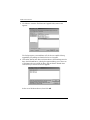
Starting the Upgrade. . . . . . . . . . . . . . . . . . . . . . . . . . . . . . . . . . . . . .43
Upgrade Succeeded . . . . . . . . . . . . . . . . . . . . . . . . . . . . . . . . . . . . . . 46
Upgrade Failed . . . . . . . . . . . . . . . . . . . . . . . . . . . . . . . . . . . . . . . . . . 47
Firmware Upgrade Recovery . . . . . . . . . . . . . . . . . . . . . . . . . . . . . . . . . .48
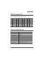
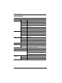
Appendix
KH0116 Connection Table . . . . . . . . . . . . . . . . . . . . . . . . . . . . . . . . . . . . 49
OSD Factory Default Settings. . . . . . . . . . . . . . . . . . . . . . . . . . . . . . . . . . 49
Specifications . . . . . . . . . . . . . . . . . . . . . . . . . . . . . . . . . . . . . . . . . . . . . . 50
Administrator Login Failure. . . . . . . . . . . . . . . . . . . . . . . . . . . . . . . . . . . . 51
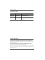
Troubleshooting . . . . . . . . . . . . . . . . . . . . . . . . . . . . . . . . . . . . . . . . . . . . 52
Limited Warranty. . . . . . . . . . . . . . . . . . . . . . . . . . . . . . . . . . . . . . . . . . . .52

KH0116 User Manual
xi
About This Manual
This User Manual is provided to help you get the most from your KH0116
system. It covers all aspects of installation, configuration and operation. An
overview of the information found in the manual is provided below.
Overview
Chapter 1, Introduction, introduces you to the KH0116 System. Its
purpose, features and benefits are presented, and its front and back panel
components are described.
Chapter 2, Installation and Operation, provides step-by-step
instructions for setting up your installation, and explains some basic operation
procedures.
Chapter 3, OSD Operation, provides a complete description of the
KH0116’s On Screen Display, and how to work with it.
Chapter 4, Hotkey Operation, details all of the concepts and procedures
involved in the hotkey operation of your KH0116 installation.
Chapter 5, The Firmware Upgrade Utility, explains how to upgrade the
KH0116’s firmware to the latest available version.
An Appendix, at the end of the manual provides specifications and other
technical information regarding the KH0116.

KH0116 User Manual
xii
Conventions
This manual uses the following conventions:
Monospaced Indicates text that you should key in.
[ ]
Indicates keys you should press. For example, [Enter] means
to press the Enter key. If keys need to be chorded, they
appear together in the same bracket with a plus sign
between them: [Ctrl+Alt].
1.
Numbered lists represent procedures with sequential steps.
♦
Bullet lists provide information, but do not involve sequential
steps.
→
Indicates selecting the option (on a menu or dialog box, for
example), that comes next. For example, Start
→ Run
means to open the Start menu, and then select Run.
Indicates critical information.

KH0116 User Manual
xiii
ALTUSEN Information
Technical Support
Getting Help
For additional help, advice, and information, ALTUSEN provides several
support options. If you need to contact ALTUSEN technical support with a
problem, please have the following information ready beforehand:
Product model number, serial number, and date of purchase.
Your computer configuration, including operating system, revision level,
expansion cards, and software.
Any error messages displayed at the time the error occurred.
The sequence of operations that led up to the error.
Any other information you feel may be of help
North America Technical
Phone Support
Registered ALTUSEN product owners are entitled to
telephone technical support. Call the ALTUSEN
Technical Support Center: 949-453-8885.
International Technical
Phone Support
1. Contact your local dealer.
2. Call the ALTUSEN Technical Support Cen-
ter:(886-2) 8692-6959.
Email Support Email your questions and concerns to:
Online Support
Troubleshooting
Documentation
Software Updates
Online troubleshooting that describes the most com-
monly encountered problems and offers possible
solutions to them; online documentation (including
electronically available manuals); and the latest driv-
ers and firmware for your product are available at the
ALTUSEN website: http://www.altusen.com

KH0116 User Manual
xiv
Product Information
For information about all of ALTUSEN's products and how they can help you
connect without limits, visit ALTUSEN on the web or contact an ALTUSEN
Authorized Reseller.
In the United States of America, call: 866-ALTUSEN (258-8736)
In Canada and South America, call: 949-453-8885
In all other locations, call: 886-2-8692-6789
Visit ALTUSEN on the web at http://www.altusen.com for a list of
locations and telephone numbers

1
Chapter 1
Introduction
Overview
The KH0116 KVM Switch is a control units that allow access to multiple
computers from a single KVM (keyboard, monitor, and mouse) console.
Before the development of sophisticated KVM switches, the only way to
control large-scale multiple computer configurations from a single console was
through a complex and costly network system. Now, with the KH0116, you can
easily access multiple computers in a cost effective manner.
A single KH0116 can control up to 16 computers. As many as 31 additional
KH0116 can be daisy chained to each other, so that up to 512 computers can
all be controlled from a single keyboard-monitor-mouse console.
A custom ASIC (patent pending) provides an auto-sensing function that
recognizes the position of each station on the chain, eliminating the need to
manually set the position with DIP switches. A seven segment front panel LED
displays each Station's position for easy identification.
For further convenience, the KH0116 features high density 15 pin connectors
instead of the usual 25 pin connectors. This space-saving innovation allows a
full, 16 port switch, to be installed in a 1U system rack.
Your KH0116 investment is protected by an included Firmware Upgrade
Utility. You can stay current with the latest functionality improvements by
downloading firmware update files from our website as they become available,
and using the utility to quickly and conveniently perform the upgrade.
Setting up the KH0116 is fast and easy; plugging cables into their appropriate
ports is all that is entailed. Because the KH0116 intercepts keyboard input
directly, there is no software to configure, so there is no need to get involved
in complex installation routines or be concerned with incompatibility
problems.

KH0116 User Manual
2
Access to any computer on the installation is easily accomplished either by
entering Hotkey combinations from the keyboard, or by means of a powerful
menu driven OSD (On Screen Display) system. A convenient Auto Scan
feature also permits automatic scanning and one-by-one monitoring of the
activities of selected computers on the installation.
There is no better way to save time and money than with a KH0116 installation.
By allowing a single console to manage all the attached computers, a KH0116
installation: (1) eliminates the expense of having to purchase a separate
keyboard, monitor, and mouse for each computer; (2) saves all the space those
extra components would take up; (3) saves on energy costs; and (4) eliminates
the inconvenience and wasted effort involved in constantly moving from one
computer to another.

Chapter 1. Introduction
3
Features
A single console controls up to 16 computers
Dedicated chain ports - daisy chain up to 31 additional units - control up to
512 computers from a single console
No software required - convenient computer selection via Hotkeys and
intuitive On Screen Display (OSD) menus
Auto Scan feature for monitoring user-selected computers
Hot Pluggable - add or remove switches/computers without having to
power down the switches
Custom ASIC (patent pending) auto-senses station's position on daisy
chained installations - no need for manual DIP switch setting - front panel
LED indicates station's position
Port names automatically reconfigured when station sequence is changed
Two level password security - only authorized users view and control the
computers - up to four Users plus an Administrator - separate profiles for
each
Two level logout - Manual and Timed
Keyboard and mouse emulation - computers boot even when the console
focus is elsewhere - Keep Alive function - the keyboard and mouse work
properly even if the switch temporarily loses power
Supports* PS/2 Compatible Mice, Microsoft Intellimouse Explorer,
Logitech FirstMouse+
Superior video quality - resolutions of up to 1920 x 1440 - each port
supports DDC2B
Supports a second remote console (up to 150 m away)
Firmware upgradable
Full range universal internal power supply
Rack Mountable in 19" System Rack (1U)
Note:1.PS/2 compatible mouse support is for 3 button wheel mice.
2. The Logitech Mouse Ware program's Change Device procedure does
not work on Microsoft NT computers.

KH0116 User Manual
4
Hardware Requirements
Console
A VGA, SVGA, or Multisync monitor capable of the highest resolution
that you will be using on any computer in the installation.
A PS/2 style mouse
A PS/2 style keyboard
Computers
The following equipment must be installed on each computer:
A VGA, SVGA or Multisync card.
A 6-pin mini-DIN (PS/2 style) mouse port.
A 6-pin mini-DIN (PS/2 Style) keyboard port.
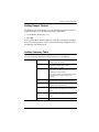
Cables
Substandard cables may damage the connected devices or degrade overall
performance. For optimum signal integrity and to simplify the layout, we
strongly recommend that you use the high quality Custom Cable sets described
below:
Function CS Part Number
KVM Switch to KVM Switch (Daisy Chaining) 2L-1700 - 0.6 m
2L-1701 - 1.8 m
KVM Switch to Computer 2L-5201P - 1.2 m
2L-5202P - 1.8 m
2L-5203P - 3.0 m

Chapter 1. Introduction
5
Components
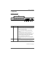
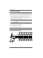
KH0116 Front View
(Continues on next page.)
No. Component Description
1 Port LEDs The Port LEDs provide status information about their
corresponding Computer Ports. There is one pair of LEDs for
each Port. The one on the left is the On Line LED; the one on
the right is the Selected Port LED:
An On Line LED lights ORANGE to indicate that the
computer attached to its corresponding port is up and
running.
A Selected LED lights GREEN to indicate that the
computer attached to its corresponding port is the one that
has the KVM focus. The LED is steady under normal
conditions, but flashes when its port is accessed under
Auto Scan Mode (see F7 SCAN:, page 32).
When the KH0116 is first powered on, the On Line and
Selected LEDs blink in sequence as the Switch performs a
self-test.
2 Reset Switch Pressing this switch in performs a system reset.
Note: The switch is recessed and must be pushed with a thin
object - such as the end of a paper clip, or a ballpoint pen.
23
1
564

KH0116 User Manual
6
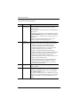
(Continued from previous page.)
No. Component Description
3 Remote
Console Area
The KH0116 can be operated from a remote console (up to
150m away) with the purchase of the CE-250 KVM
Extender system.
If you choose to use a remote console, its cable plugs into
this connector.
Normally, both consoles can access the KH0116. Clicking
the Disable Remote button to the In position disables the
Remote Console – only the Local Console has access to
the switch.
Details on using the KH0116 with the CE-250 KVM
Extender system are provided on page 13.
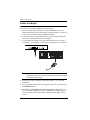
4 Firmware
Upgrade Area
This area consists of two components: The Firmware
Upgrade Port; and the Firmware Upgrade Reset Switch.
The Firmware Upgrade Cable that transfers the
firmware upgrade data from the administrator's
computer to the KH0116 (see p. 42), plugs into the
Firmware Upgrade Port's RJ-11 connector.
During normal operation and while performing a
firmware upgrade, this switch should be in the NORMAL
position. If a firmware upgrade operation does not
complete successfully, slide this switch to the
RECOVER position and do a warm reset to return the
switch to its prior firmware state.
After returning the switch to its prior firmware state,
slide the switch back to the NORMAL position to
attempt the firmware upgrade again, or to use the
switch with its prior firmware.
5 Power LED Lights to indicate that the KH0116 is powered up and
ready to operate.
6 Station ID LED The KH0116's Station ID is displayed here. If this is a
Single Station installation (see p. 10), or the First Station
on a Daisy Chained installation (see p. 11), the KH0116
has a Station ID of 01.
On a Daisy Chained installation, the KH0116 auto-senses
its position and displays the Station ID that corresponds to
its place in the chain. (see Port ID Numbering, p. 17 for
details).
Page is loading ...
Page is loading ...
Page is loading ...
Page is loading ...
Page is loading ...
Page is loading ...
Page is loading ...
Page is loading ...
Page is loading ...
Page is loading ...
Page is loading ...
Page is loading ...
Page is loading ...
Page is loading ...
Page is loading ...
Page is loading ...
Page is loading ...
Page is loading ...
Page is loading ...
Page is loading ...
Page is loading ...
Page is loading ...
Page is loading ...
Page is loading ...
Page is loading ...
Page is loading ...
Page is loading ...
Page is loading ...
Page is loading ...
Page is loading ...
Page is loading ...
Page is loading ...
Page is loading ...
Page is loading ...
Page is loading ...
Page is loading ...
Page is loading ...
Page is loading ...
Page is loading ...
Page is loading ...
Page is loading ...
Page is loading ...
Page is loading ...
Page is loading ...
Page is loading ...
Page is loading ...
Page is loading ...
Page is loading ...
Page is loading ...
-
 1
1
-
 2
2
-
 3
3
-
 4
4
-
 5
5
-
 6
6
-
 7
7
-
 8
8
-
 9
9
-
 10
10
-
 11
11
-
 12
12
-
 13
13
-
 14
14
-
 15
15
-
 16
16
-
 17
17
-
 18
18
-
 19
19
-
 20
20
-
 21
21
-
 22
22
-
 23
23
-
 24
24
-
 25
25
-
 26
26
-
 27
27
-
 28
28
-
 29
29
-
 30
30
-
 31
31
-
 32
32
-
 33
33
-
 34
34
-
 35
35
-
 36
36
-
 37
37
-
 38
38
-
 39
39
-
 40
40
-
 41
41
-
 42
42
-
 43
43
-
 44
44
-
 45
45
-
 46
46
-
 47
47
-
 48
48
-
 49
49
-
 50
50
-
 51
51
-
 52
52
-
 53
53
-
 54
54
-
 55
55
-
 56
56
-
 57
57
-
 58
58
-
 59
59
-
 60
60
-
 61
61
-
 62
62
-
 63
63
-
 64
64
-
 65
65
-
 66
66
-
 67
67
-
 68
68
-
 69
69


Ask a question and I''ll find the answer in the document
Finding information in a document is now easier with AI
Related papers


Other documents
-
 Altusen KH0116 User manual
-
MicroNet SP236 User manual
-
 Altusen KH0116 User manual
-
-
Altusen ALTUSEN PN9108U User manual
-
ATEN Technology CE-250 User manual
-
Hawking Technology CS152F User manual
-
-
Zonet KVM3324 Installation guide
-
IC Intracom 524513 Datasheet

