Page is loading ...

Crestron HD-MD8X1/HD-MD8X2
QuickSwitch HD
®
HDMI
®
Switcher
Operations & Installation Guide

The specific patents that cover Crestron products are listed at patents.crestron.com
Regulatory Compliance
As of the date of manufacture, the HD-MD8X1 and HD-MD8X2 have been tested and found to comply with
specifications for CE marking and standards per EMC and Radiocommunications Compliance Labelling.
Federal Communications Commission (FCC) Compliance Statement
This device complies with part 15 of the FCC Rules. Operation is subject to the following conditions:
(1) This device may not cause harmful interference and (2) this device must accept any interference received,
including interference that may cause undesired operation.
CAUTION: Changes or modifications not expressly approved by the manufacturer responsible for
compliance could void the user’s authority to operate the equipment.
NOTE: This equipment has been tested and found to comply with the limits for a Class B digital device,
pursuant to part 15 of the FCC Rules. These limits are designed to provide reasonable protection against
harmful interference in a residential installation. This equipment generates, uses and can radiate radio
frequency energy and, if not installed and used in accordance with the instructions, may cause harmful
interference to radio communications. However, there is no guarantee that interference will not occur in a
particular installation. If this equipment does cause harmful interference to radio or television reception,
which can be determined by turning the equipment off and on, the user is encouraged to try to correct the
interference by one or more of the following measures:
Reorient or relocate the receiving antenna
Increase the separation between the equipment and receiver
Connect the equipment into an outlet on a circuit different from that to which the receiver is connected
Consult the dealer or an experienced radio/TV technician for help
Industry Canada (IC) Compliance Statement
CAN ICES-3(B)/NMB-3(B)
.
Crestron, the Crestron logo, Cresnet, Crestron e-Control, Crestron Studio, Crestron Toolbox, and QuickSwitch HD are either trademarks or registered
trademarks of Crestron Electronics, Inc. in the United States and/or other countries. Blu-ray Disc is either a trademark or registered trademark of the
Blu-ray Disc Association in the United States and/or other countries. Dolby and Dolby Digital are either trademarks or registered trademarks of Dolby
Laboratories in the United States and/or other countries. DTS and DTS-HD Master Audio are either trademarks or registered trademarks of DTS, Inc.
in the United States and/or other countries. HDMI and the HDMI Logo are either trademarks or registered trademarks of HDMI Licensing LLC in the
United States and/or other countries. Other trademarks, registered trademarks, and trade names may be used in this document to refer to either the
entities claiming the marks and names or their products. Crestron disclaims any proprietary interest in the marks and names of others. Crestron is not
responsible for errors in typography or photography.
This document was written by the Technical Publications department at Crestron.
©2013 Crestron Electronics, Inc.

Crestron HD-MD8X1/HD-MD8X2 QuickSwitch HD HDMI Switcher
Operations & Installation Guide – DOC. 6714B Contents i
Contents
QuickSwitch HD HDMI Switcher: HD-MD8X1/HD-MD8X2 1
Introduction ...............................................................................................................................1
Features and Functions................................................................................................ 1
Applications.................................................................................................................4
Internal Block Diagram ............................................................................................... 4
Specifications ..............................................................................................................5
Physical Description....................................................................................................8
Setup ........................................................................................................................................ 12
Network Wiring.........................................................................................................12
Identity Code ............................................................................................................. 12
Installation................................................................................................................. 13
Hardware Hookup .....................................................................................................15
HDCP Signal Path ..................................................................................................... 15
EDID .........................................................................................................................17
Uploading and Upgrading........................................................................................................ 18
Establishing Communication.....................................................................................18
Programs and Firmware ............................................................................................19
Program Checks ........................................................................................................ 20
Operation .................................................................................................................................21
Operating Modes .......................................................................................................21
View Mode................................................................................................................. 21
Route Mode ............................................................................................................... 22
Problem Solving ......................................................................................................................23
Troubleshooting......................................................................................................... 23
Check Network Wiring..............................................................................................23
Reference Documents................................................................................................ 24
Further Inquiries ........................................................................................................25
Future Updates ..........................................................................................................25
Return and Warranty Policies .................................................................................................. 26
Merchandise Returns / Repair Service ...................................................................... 26
Crestron Limited Warranty........................................................................................26


Crestron HD-MD8X1/HD-MD8X2 QuickSwitch HD HDMI Switcher
Operations & Installation Guide – DOC. 6714B QuickSwitch HD HDMI Switcher: HD-MD8X1/HD-MD8X2 1
QuickSwitch HD HDMI
Switcher: HD-MD8X1/
HD-MD8X2
Introduction
QuickSwitch HD
®
switchers from Crestron
®
enable high-performance HDMI
®
signal
selection while delivering fast, trouble-free switching of all DVD and Blu-ray Disc
®
players, HDTV receivers, media servers, game consoles, multimedia computers,
surround processors, and high-definition displays in a system. The HD-MD8X1
features eight HDMI inputs and a single HDMI output to feed a video display or
processor. The HD-MD8X2 features eight HDMI inputs and two independently
switchable HDMI outputs to feed two separate displays or to support a single display
that has built-in PIP capability.
For simplicity within this guide, the term “HD-MD8X1/2” is used except where
noted.
HDMI is the standard for interfacing high-definition AV equipment and is key to
handling the latest HD video and audio formats. Providing unparalleled performance,
functionality, and custom integration capability, the HD-MD8X1/2 supports HDMI
with HDCP, Deep Color, and 3D, handling 1080p60 HD video and WUXGA
computer resolutions as well as multichannel HD lossless audio.
Features and Functions
High-performance 8 x 1 or 8 x 2 HDMI switcher
QuickSwitch HD switching technology
Handles HDMI with Deep Color, 3D, and 7.1 linear PCM or
high-bitrate encoded audio
Compatible with DVI and DisplayPort Multimode*
Supports video resolutions up to WUXGA 1920 x 1200 and
HD 1080p60
Detects and reports detailed video and audio input information
(Continued on following page)
* HDMI IN requires an appropriate adapter or interface cable to accommodate a DVI or DisplayPort
Multimode signal. HDMI OUT requires an appropriate adapter or interface cable to accommodate a
DVI signal. CBL-HD-DVI interface cable sold separately.

QuickSwitch HD HDMI Switcher Crestron HD-MD8X1/HD-MD8X2
2 QuickSwitch HD
HDMI Switcher: HD-MD8X1/HD-MD8X2 Operations & Installation Guide – DOC. 6714B
Features and Functions
(Continued)
Manages HDCP digital rights management for all connected devices
Performs automatic AV signal format management via EDID
HD-SCALER option (sold separately) ensures optimal image quality
for all sources
Includes front panel controls with security lockout
Allows audio breakaway switching
Simple setup and diagnostics via software
Native control system integration via Ethernet or Cresnet
®
Single-space 19-inch rack-mountable
QuickSwitch HD Technology
Handling high-definition digital media means handling HDCP (High-bandwidth
Digital Content Protection), the encryption scheme that content providers use to
protect their DVDs, Blu-ray discs, and broadcast signals against unauthorized
copying. Viewing HDCP encrypted content requires a source device to
“authenticate” each display and signal processor in the system and issue each one a
“key” before the content can be viewed. Ordinarily, this causes a complete loss of
signal for up to 15 seconds each time a new source or display is selected anywhere in
the system. In addition, every source device has a limited number of keys available;
therefore, if too many displays are connected, the source stops outputting a signal
without warning. Crestron QuickSwitch HD, however, manages the keys for every
HDCP-compliant device in the system, maintaining continuous authentication for
each device to ensure fast, reliable switching.
EDID Format Management
With HDMI comes a multitude of confusing video and audio formats to keep track
of, and chances are that not every device in a system supports all of the same
formats. The HD-MD8X1/2 eliminates any conflicts by managing the EDID
(Extended Display Identification Data) that HDMI devices use to communicate their
capabilities. Via Crestron Toolbox™ software, the format and resolution capabilities
of each device can be assessed, allowing the installer to configure EDID signals
appropriately for the most desirable and predictable behavior. Signal information
such as resolution, frame rate, aspect ratio, color depth, and audio format can also be
sent to the control system and displayed on a touch screen to allow custom
functionality and enhanced diagnostics.
High-Definition Scaler Option
High-performance scaling capability can be added to the HD-MD8X1/2 using the
optional HD-SCALER (sold separately). The HD-SCALER features fully automatic
operation and is compact enough to install at the display location, ensuring an
optimal image regardless of the source that is selected. It also provides analog video
and audio inputs to accommodate additional analog sources.

Crestron HD-MD8X1/HD-MD8X2 QuickSwitch HD HDMI Switcher
Operations & Installation Guide – DOC. 6714B QuickSwitch HD HDMI Switcher: HD-MD8X1/HD-MD8X2 3
Computer Compatibility
Besides handling every available HD format supported by HDMI, the
HD-MD8X1/2 also supports computer resolutions up to 1920 x 1200 WUXGA, and
is compatible with DVI and DisplayPort Multimode computer signals using a
suitable adapter or dongle*.
Audio Breakaway
Audio signals may be routed independently of video in the HD-MD8X1/2, allowing
listening to one source while viewing another. For instance, listening to favorite
music from a media server is possible while playing a video game or surfing the
Internet on screen.
Front Panel Controls
The HD-MD8X1/2 works out of the box without requiring any connection to a
control system or computer, providing intuitive signal switching via its front panel.
The front panel is great for everyday use, or may be used just for initial system
testing. Front panel buttons may be locked out to prevent unauthorized tampering or
accidental switching, while the LED indicators remain active to show signal routing
status. The input and output controls can be labeled easily using Crestron Engraver
software or standard 3/8" (10 mm) tape labels.
Native Crestron Control
Via the choice of Cresnet
®
or high-speed Ethernet, the HD-MD8X1/2 allows direct
communication with a Crestron control system for a fully integrated signal routing
solution as part of any high-end home theater, boardroom, classroom, or command
center system.
Easy Setup
Despite its many powerful features and capabilities, the HD-MD8X1/2 is simple to
set up using Crestron Toolbox software. The Toolbox setup tool allows the installer
to view information about each HDMI device and easily make intelligent choices to
ensure a reliable system setup.
* HDMI IN requires an appropriate adapter or interface cable to accommodate a DVI or DisplayPort
Multimode signal. HDMI OUT requires an appropriate adapter or interface cable to accommodate a
DVI signal. CBL-HD-DVI interface cable sold separately.

QuickSwitch HD HDMI Switcher Crestron HD-MD8X1/HD-MD8X2
4 QuickSwitch HD
HDMI Switcher: HD-MD8X1/HD-MD8X2 Operations & Installation Guide – DOC. 6714B
Applications
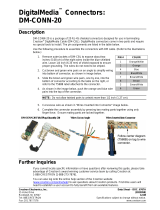
The following diagram shows an HD-MD8X2 in a residential application.
HD-MD8X2 in a Residential Application
Internal Block Diagram
The following diagram represents the switching abilities of the HD-MD8X1/2.
Internal Block Diagram of the HD-MD8X1/2
HDMI RX
(8)
HDMI TX
(1 or 2)
Digital Video
Switch
Digital Audio
Switch

Crestron HD-MD8X1/HD-MD8X2 QuickSwitch HD HDMI Switcher
Operations & Installation Guide – DOC. 6714B QuickSwitch HD HDMI Switcher: HD-MD8X1/HD-MD8X2 5
Specifications
Specifications for the HD-MD8X1/2 are listed in the following table.
HD-MD8X1/2 Specifications
SPECIFICATION DETAILS
Video
Switcher
HD-MD8X1: 8 x 1 digital matrix, resolution
management, Crestron QuickSwitch HD
HD-MD8X2: 8 x 2 digital matrix, resolution
management, Crestron QuickSwitch HD
Input Signal Types
HDMI, DVI*, DisplayPort Multimode*
Output Signal Types
HDMI, DVI*
Formats HDMI with Deep Color and 3D, DVI, HDCP
content protection support
Input Resolutions
Progressive 640 x 480 @ 60 Hz
720 x 480 @ 60 Hz (480p)
720 x 576 @ 50 Hz (576p)
800 x 600 @ 60 Hz
848 x 480 @ 60 Hz
852 x 480 @ 60 Hz
854 x 480 @ 60 Hz
1024 x 768 @ 60 Hz
1024 x 852 @ 60 Hz
1024 x 1024 @ 60 Hz
1280 x 720 @ 50 Hz (720p50)
1280 x 720 @ 60 Hz (720p60)
1280 x 768 @ 60 Hz
1280 x 800 @ 60 Hz
1280 x 960 @ 60 Hz
1280 x 1024 @ 60 Hz
1360 x 768 @ 60 Hz
1365 x 1024 @ 60 Hz
1366 x 768 @ 60 Hz
1400 x 1050 @ 60 Hz
1440 x 900 @ 60 Hz
1600 x 900 @ 60 Hz
1600 x 1200 @ 60 Hz
1680 x 1050 @ 60 Hz
1920 x 1080 @ 24 Hz (1080p24)
1920 x 1080 @ 25 Hz (1080p25)
1920 x 1080 @ 50 Hz (1080p50)
1920 x 1080 @ 60 Hz (1080p60)
1920 x 1200 @ 60 Hz
2048 x 1080 @ 24 Hz
2048 x 1152 @ 60 Hz
plus any other resolution allowed by HDMI up to
165 MHz pixel clock
Interlaced
720 x 480 @ 30 Hz (480i)
720 x 576 @ 25 Hz (576i)
1920 x 1080 @ 25 Hz (1080i25)
1920 x 1080 @ 30 Hz (1080i30)
plus any other resolution allowed by HDMI up to
165 MHz pixel clock
(Continued on following page)

QuickSwitch HD HDMI Switcher Crestron HD-MD8X1/HD-MD8X2
6 QuickSwitch HD
HDMI Switcher: HD-MD8X1/HD-MD8X2 Operations & Installation Guide – DOC. 6714B
HD-MD8X1/2 Specifications (Continued)
SPECIFICATION DETAILS
Video (Continued)
Output Resolutions Matched to inputs
Audio
Switcher
HD-MD8X1: 8 x 1 digital multichannel
switching, audio-follow-video or breakaway
HD-MD8X2: 8 x 2 digital multichannel
switching, audio-follow-video or breakaway
Input Signal Types HDMI, DisplayPort Multimode*
Output Signal Type HDMI
Formats
Dolby Digital
®
, Dolby Digital EX, Dolby Digital
Plus, Dolby
®
TrueHD, DTS
®
, DTS-ES, DTS
96/24, DTS-HD High Res, DTS-HD Master
Audio™, up to 8 channel PCM
Communications
Ethernet
For control and console;
10/100 Mbps, auto-switching, auto-negotiating,
auto-discovery, full/half duplex, DHCP
Cresnet For control and console, Cresnet slave
USB For console, USB 2.0 client
HDMI Provides EDID and HDCP key management
Power
Cresnet Power Usage
HD-MD8X1: 26 W (1.09 A @ 24 Vdc)
HD-MD8X2: 27 W (1.13 A @ 24 Vdc)
Default Net ID 9B
Environmental
Temperature 32º to 104º F (0º to 40º C)
Humidity 10% to 90% RH (non-condensing)
Heat Dissipation 92 Btu/h
Enclosure
Chassis
Metal, black finish, convection-cooled, vented
top and sides
Faceplate
Metal, black finish with polycarbonate label
overlay
Mounting
Freestanding or 1 U 19-inch rack-mountable
(adhesive feet and rack ears included)
Dimensions
Height
1.70 in (44 mm) without feet;
1.80 in (46 mm) with feet
Width
17.03 in (433 mm) without ears;
19.00 in (483 mm) with ears
Depth 10.06 in (256 mm)
Weight 4.1 lb (1.9 kg)
(Continued on following page)

Crestron HD-MD8X1/HD-MD8X2 QuickSwitch HD HDMI Switcher
Operations & Installation Guide – DOC. 6714B QuickSwitch HD HDMI Switcher: HD-MD8X1/HD-MD8X2 7
HD-MD8X1/2 Specifications (Continued)
SPECIFICATION DETAILS
Available Accessories
CBL-HD Crestron Certified HDMI Interface Cable
CBL-HD-DVI Crestron Certified HDMI to DVI Interface Cable
CBL-HD-LOCK Locking High-Speed HDMI Cable
DMCI DigitalMedia Card Interface
HD-DA-2
1-to-2 HDMI Distribution Amplifier and Audio
Converter
HD-EXT1-C HDMI over Shielded Twisted Pair Extender
HD-EXT2-C HDMI over Shielded Twisted Pair Extender
HD-RX1-F HDMI over Fiber Receiver
HD-RX3-F HDMI over Fiber Receiver
HD-SCALER High-Definition Video Scaler
HD-TX1-F HDMI over Fiber Transmitter
HD-TX3-F HDMI over Fiber Transmitter
* HDMI IN requires an appropriate adapter or interface cable to accommodate a DVI or DisplayPort
Multimode signal. HDMI OUT requires an appropriate adapter or interface cable to accommodate a
DVI signal. CBL-HD-DVI interface cable sold separately.

QuickSwitch HD HDMI Switcher Crestron HD-MD8X1/HD-MD8X2
8 QuickSwitch HD
HDMI Switcher: HD-MD8X1/HD-MD8X2 Operations & Installation Guide – DOC. 6714B
Physical Description
This section provides information on the connections, controls, and indicators
available on the HD-MD8X1/2.
HD-MD8X1 Physical Views (Front and Rear)
HD-MD8X2 Physical Views (Front and Rear)

Crestron HD-MD8X1/HD-MD8X2 QuickSwitch HD HDMI Switcher
Operations & Installation Guide – DOC. 6714B QuickSwitch HD HDMI Switcher: HD-MD8X1/HD-MD8X2 9
HD-MD8X1/2 Overall Dimensions (HD-MD8X2 Shown)
9.75 in
(248 mm)
10.06 in
(256 mm)
17.03 in
(433 mm)
1.70 in
(44 mm)
HD-MD8X1/2 Connectors, Controls, and Indicators (HD-MD8X2 Shown)
11
1
2
10
12 13
14
15
3
4
5
6
7
89
16

QuickSwitch HD HDMI Switcher Crestron HD-MD8X1/HD-MD8X2
10 QuickSwitch HD
HDMI Switcher: HD-MD8X1/HD-MD8X2 Operations & Installation Guide – DOC. 6714B
Connectors, Controls, and Indicators
#
CONNECTORS
1
,
CONTROLS, AND
INDICATORS
DESCRIPTION
1 PWR LED
(1) Green LED, indicates 24 Vdc power
supplied from Cresnet control network
2 NET LED
(1) Amber LED, indicates communication with
Cresnet system
3
SYNC
(Button and LED)
(1) Recessed push button and red LED,
selects Sync mode for viewing input signal
sensing
4
VIEW
(Button and LED)
(1) Push button and red LED, selects View
mode for viewing current routes
5
ROUTE
(Button and LED)
(1) Push button and red LED, selects Route
mode to allow routing changes
6
A
(Button and LED)
(1) Push button and red LED, selects audio
routing view
7
V
(Button and LED)
(1) Push button and red LED, selects video
routing view
8
IN 1-8
(Buttons and LEDs)
(8) Push buttons and red LEDs, select input
for routing
9
OUT 1/OUT 1-2
(Buttons and LEDs)
HD-MD8X1 (1) or HD-MD8X2 (2) push
buttons and red LEDs, select output for
routing
10
INPUT 1-8
(8) 19-pin Type A HDMI female;
HDMI digital video/audio inputs;
Supports DVI and DisplayPort Multimode
2
11
OUTPUT 1/
OUTPUT 1-2
HD-MD8X1 (1) or HD-MD8X2 (2) 19-pin
Type A HDMI female;
HDMI digital video/audio outputs;
Supports DVI
2
12
LAN
Green
LED
Amber
LED
Pin 8
Pin 1
(1) 8-pin RJ-45 with two LED indicators;
10BASE-T/100BASE-TX Ethernet port,
Green LED indicates link status;
Amber LED indicates Ethernet activity
PIN SIGNAL PIN SIGNAL
1 TX + 5 N/C
2 TX - 6 RC -
3 RC + 7 N/C
4 N/C 8 N/C
13
COMPUTER
(1) USB Type B female;
USB 2.0 computer console port
(6 ft cable included)
14
SETUP
(Button and LED)
(1) Miniature push button and red LED, used
for touch-settable ID (TSID) and Ethernet
autodiscovery
(Continued on following page)

Crestron HD-MD8X1/HD-MD8X2 QuickSwitch HD HDMI Switcher
Operations & Installation Guide – DOC. 6714B QuickSwitch HD HDMI Switcher: HD-MD8X1/HD-MD8X2 11
Connectors, Controls, and Indicators (Continued)
#
CONNECTORS
1
,
CONTROLS, AND
INDICATORS
DESCRIPTION
15
NET
24 Y Z G
24 Y Z G
(2) 4-pin 3.5 mm detachable terminal blocks;
Cresnet slave ports, paralleled
24: Power (24 Vdc)
Y: Data
Z: Data
G: Ground
16
G
(1) 6-32 screw, chassis ground lug
1. Interface connectors for the NET ports are provided with the unit.
2. HDMI IN requires an appropriate adapter or interface cable to accommodate a DVI or DisplayPort
Multimode signal. HDMI OUT requires an appropriate adapter or interface cable to accommodate a
DVI signal. CBL-HD-DVI interface cable sold separately.

QuickSwitch HD HDMI Switcher Crestron HD-MD8X1/HD-MD8X2
12 QuickSwitch HD
HDMI Switcher: HD-MD8X1/HD-MD8X2 Operations & Installation Guide – DOC. 6714B
Setup
Network Wiring
When wiring the Cresnet and Ethernet network, consider the following:
Use Crestron Certified Wire.
Use Crestron power supplies for Crestron equipment.
Provide sufficient power to the system.
CAUTION: Insufficient power can lead to unpredictable results or damage
to the equipment. Please use the Crestron Power Calculator to help calculate
how much power is needed for the system (www.crestron.com/calculators
).
For Cresnet networks with 20 or more devices, use a Cresnet Hub/Repeater
(CNXHUB) to maintain signal quality.
For more details, refer to “Check Network Wiring” on page 23.
The
HD-MD8X1/2 can also use high-speed Ethernet for communications between
the control system, computer, media server, and other IP-based devices.
For general information on connecting Ethernet devices in a Crestron system, refer to
the Crestron e-Control
Reference Guide (Doc. 6052) at
www.crestron.com/manuals
.
Identity Code
Net ID
The Net ID of the HD-MD8X1/2 has been factory set to 9B. The Net IDs of multiple
HD-MD8X1/2 devices in the same system must be unique. Net IDs are changed
from a personal computer (PC) via Crestron Toolbox (refer to “Establishing
Communication” on page 18).
Wh
en setting the Net ID, consider the following:
The Net ID of each unit must match an ID code specified in the Crestron
Studio™ or SIMPL Windows program.
Each network device must have a unique Net ID.
For more details, refer to the Crestron Toolbox help file.
IP ID
The IP ID is set within the HD-MD8X1/2’s IP table using Crestron Toolbox. For
information on setting an IP table, refer to the Crestron Toolbox help file. The IP IDs
of multiple HD-MD8X1/2 devices in the same system must be unique.
When setting the IP ID, consider the following:
The IP ID of each unit must match an IP ID specified in the Crestron Studio
or SIMPL Windows program.
Each device using IP to communicate with a control system must have a
unique IP ID.

Crestron HD-MD8X1/HD-MD8X2 QuickSwitch HD HDMI Switcher
Operations & Installation Guide – DOC. 6714B QuickSwitch HD HDMI Switcher: HD-MD8X1/HD-MD8X2 13
Installation
Ventilation
The HD-MD8X1/2 should be used in a well-ventilated area. The venting holes
should not be obstructed under any circumstances.
To prevent overheating, do not operate this product in an area that exceeds the
environmental temperature range listed in the table of specifications. Consider using
forced air ventilation and/or incrementing the spacing between units to reduce
overheating. Contact with thermal insulating materials should be avoided on all sides
of the unit.
Rack Mounting
The HD-MD8X1/2 can be mounted in a rack or stacked with other equipment. Two
“ears” are provided with the HD-MD8X1/2 for rack mounting. These ears must be
installed prior to mounting. Complete the following procedure to attach the ears to
the unit. The only tool required is a #2 Phillips screwdriver.
WARNING: To prevent bodily injury when mounting or servicing this unit in a
rack, observe the following guidelines:
When mounting this unit in a partially filled rack, load the rack from the
bottom to the top with the heaviest component at the bottom of the rack.
If the rack is provided with stabilizing devices, install the stabilizers before
mounting or servicing the unit in the rack.
NOTE: Observe the following guidelines when installing equipment in a rack:
Elevated Operating Ambient Temperature - If installed in a closed or
multi-unit rack assembly, the operating ambient temperature of the rack
environment may be greater than room ambient temperature. Therefore,
consideration should be given to installing the equipment in an environment
compatible with the maximum ambient temperature (Tma) specified by the
manufacturer.
Reduced Air Flow - Installation of the equipment in a rack should be such
that the amount of airflow required for safe operation of the equipment is
not compromised.
Mechanical Loading - Mounting of the equipment in the rack should be
such that a hazardous condition is not achieved due to uneven mechanical
loading.
Circuit Overloading - Consideration should be given to the connection of
the equipment to the supply circuit and the effect that overloading of the
circuits might have on overcurrent protection and supply wiring.
Appropriate consideration of equipment nameplate ratings should be used
when addressing this concern.
Reliable Earthing - Reliable earthing of rack-mounted equipment should be
maintained. Particular attention should be given to supply connections other
than direct connections to the branch circuit (e.g., use of power strips).
NOTE: If rack mounting is not required, rubber feet are provided for tabletop
mounting or stacking. Apply the feet near the corner edges on the underside of the
unit.

QuickSwitch HD HDMI Switcher Crestron HD-MD8X1/HD-MD8X2
14 QuickSwitch HD
HDMI Switcher: HD-MD8X1/HD-MD8X2 Operations & Installation Guide – DOC. 6714B
To install the ears:
CAUTION: To prevent equipment damage, use only the rack ears Crestron
provides for this device.
1. There are screws that secure each side of the HD-MD8X1/2 top cover.
Using a #2 Phillips screwdriver, remove the three screws closest to the front
panel from one side of the unit. Refer to the diagram following step 3 for a
detailed view.
2. Position a rack ear so that its mounting holes align with the holes vacated
by the screws in step 1.
3. Secure the ear to the unit with three screws from step 1 as shown in the
following diagram.
Ear Attachment for Rack Mounting
Use Cover Screws
4. Repeat procedure (steps 1 through 3) to attach the remaining ear to the
opposite side.
Stacking
Four “feet” are provided with the HD-MD8X1/2 so that if the unit is not rack
mounted, the rubber feet can provide stability when the unit is placed on a flat
surface or stacked. These feet should be attached near the corners prior to the hookup
procedure.
NOTE: No more than two HD-MD8X1/2 units should be stacked.

Crestron HD-MD8X1/HD-MD8X2 QuickSwitch HD HDMI Switcher
Operations & Installation Guide – DOC. 6714B QuickSwitch HD HDMI Switcher: HD-MD8X1/HD-MD8X2 15
Hardware Hookup
Connect the Device
Make the necessary connections as called out in the illustration that follows this
paragraph. Refer to “Network Wiring” on page 12 before attaching the 4-position
t
erminal block connectors. Apply power after all connections have been made.
Hardware Connections for the HD-MD8X1/2 (HD-MD8X2 Shown)
INPUT:
From HDMI
Sources
OUTPUT 1-2:
To HDMI
Receiver
or Display
LAN:
10BASE-T/
100BASE-TX
Ethernet to LAN
COMPUTER:
To USB Port
on PC
NET:
Power from Cresnet
Power Supply and
to Cresnet Devices
Ground
NOTE: Ensure that the unit is properly grounded by connecting the chassis ground
lug to an earth ground (building steel).
NOTE: To prevent overheating, do not operate this product in an area that exceeds
the environmental temperature range listed in the table of specifications.
Label the Buttons
Use Crestron Engraver software to print custom labels for the HD-MD8X1/2’s front
panel buttons and LEDs. Crestron recommends printing on 100-pound paper. Paper
weighing less than 100 pounds tends to crumple while sliding in, while paper
weighing more than 100 pounds may not fit.
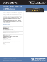
HDCP Signal Path
Sources using HDCP limit the number of display devices it can transmit to while
simultaneously limiting the depth of devices in the signal path. Too many devices or
greater than the allowed depth in a signal path (from source to display) may create
problems with the display of audio and video content. The HDCP specification states
that the maximum depth of devices between source and display is six. Examples are
provided in the following diagram.

QuickSwitch HD HDMI Switcher Crestron HD-MD8X1/HD-MD8X2
16 QuickSwitch HD
HDMI Switcher: HD-MD8X1/HD-MD8X2 Operations & Installation Guide – DOC. 6714B
Examples of Reported HDCP Devices and Reported HDCP Depth
HDMI HDMI
HDMI
HDMI HDMI HDMI
HDMI HDMI
AV Receiver
HDMI
HDMI
HDMI HDMI
Device # 1
Blu-ray
Player
Blu-ray
Player
HD-MD8X1/2
Switcher
Reported
Depth = 1
Device # 2
Display
Using HDMI
with HDCP
Reported
Depth = 0
HD-MD8X2
Switcher
Display
Using HDMI
with HDCP
Reported
Depth = 1
Device # 1 Device # 2
Reported
Depth = 0
Device # 3
Display
Using HDMI
with HDCP
Reported
Depth = 0
2 HDCP Devices
Reported Depth = 1
3 HDCP Devices
Reported Depth = 1
3 HDCP Devices
Reported Depth = 2
Blu-ray
Player
Device # 1
Reported
Depth = 2
Device # 2
Reported
Depth = 1
Device # 3
Reported
Depth = 0
HD-MD8X1/2
AV Receiver
with HDCP
Display
Using HDMI
with HDCP
4 HDCP Devices
Reported Depth = 2
Blu-ray
Player
HD-MD8X2
Reported
Depth = 2
Device # 1 Device # 2
Display
Using HDMI
with HDCP
Reported
Depth = 0
Device # 3 Device # 4
Reported
Depth = 1
Reported
Depth = 0
Display
Using HDMI
with HDCP
Using Crestron Toolbox, the switcher can test HDMI sources and displays for
switching limitations due to HDCP keys. The number of HDCP keys specifies the
number of display devices that can be connected to a source over HDMI using
HDCP authentication. For more information, refer to the Crestron Toolbox help file.
/