Page is loading ...

Before using this Stitcher, all operators must study this manual and follow the safety
warnings and instructions. Keep these instructions with the Stitcher for future
reference. If you have any questions, contact your local DeLuxe Stitcher Representative
or Distributor.
StitchMaster
OPERATION AND MAINTENANCE MANUAL
SM-A25.....StitchMaster....115 V....25 Wire
SM-CE25..StitchMaster...230 V....25 Wire
(with Stitcher Head 2001ASMHD251/2)
SM-A2125......StitchMaster....115 V....21x25 Wire
SM-CE2125....StitchMaster....230 V....21x25 Wire
(with Stitcher Head 2001ASMHD21251/2)
Machine Model : Serial Number :
Head Serial Number :
Date Purchased /Installed :
DeLuxe Stitcher
company inc.

WARNING!
StitchMaster
Machine operators and others in the work area should always wear
safety glasses to prevent serious eye injury from
fasteners and flying debris when loading, operating,
or unloading this machine.
Do not operate this stitcher without all guards in place.
The stitcher will not operate without the front guard
closed properly. Do not modify the guards in any way.
Always disconnect the power supply before removing
any guards for servicing.
Never operate the machine with wire feeding through
the head unless there is stock above the clinchers,
otherwise serious damage may result.
Always turn power off when making adjustments. Always
disconnect the power cord before any disassembly work.
2

Introduction ......................................................................................................... 4
Specifications .....................................................................................................5
Installation ....................................................................................................... 6
Pre-Inspection ................................................................................6
Inspection ......................................................................................6
Mounting ........................................................................................6
Assembly .......................................................................................7
Operation ........................................................................................................9
Wire Threading ..............................................................................9
Wire Straightening .........................................................................9
Adjustments and Settings ............................................................. 11
Stitching Process .............................................................................................14
Saddle vs. Flat Stitching ................................................................14
Stops .............................................................................................. 15
Trip Modes .....................................................................................16
Troubleshooting .............................................................................17
Maintenance ...................................................................................................... 18
Lubrication ....................................................................................18
Cleaning ........................................................................................19
How to Order Spare Parts .............................................................20
Replacing Spare Parts ................................................................... 20
Modifications .....................................................................................................24
Clincher Arm Adjustment ...............................................................24
Timing ............................................................................................26
Appendices ...................................................................................................... 27
Exploded Drawings ........................................................................ 27
Wiring Schematic ........................................................................... 37
Part Number/Description Cross Reference ..................................38
Optional Equipment .......................................................................41
Registration Card .............................................................................44
Wear/Replacement Parts ..............................................................................45
Warranty .......................................................................................................46
Declaration of Conformity ..............................................................................47
Table of Contents
3

The DeLuxe Stitcher StitchMaster is the Graphic Arts Industry’s premier, por-
table, high-quality stitcher. It is quiet, fast and very dependable, in addition to being
affordable. The StitchMaster is constructed in such a way that two machines may be
mounted side-by-side to effectively create a dual-head stitcher at a cost
considerably below that of a traditional multi-head stitcher.
There are two StitchMaster models; the SM-A which operates on 115VAC and the
SM-CE which operates on 230VAC and conforms to all pertinent CE standards. All
other performance characteristics of both models are the same.
The StitchMaster comes standard with parts for 25 gauge or smaller round wire.
However, any StitchMaster can be modified to accommodate the following wire sizes:
23 or 24 gauge round or 21 x 25 flat.
The StitchMaster has a capacity from two sheets up to 1/4” (6.4mm), or sixty
sheets of 20 pound bond paper. It accommodates both Flat and Saddle stitching. The
StitchMaster has side stops which are easily adjusted from 2.5” to 26” wide. There
are also pop-up pins for convenient corner stitching. In addition, the StitchMaster has
movable clinchers for a tight stitch and one knob adjustment for both work thickness
and centering the stitch.
The Stitchmaster has a rear contact trip and a foot switch for easy operation and
single or continuous stitch modes can be accomplished at the touch of a button. It
can clamp either to your own work table or to a heavy duty floor stand, which adjusts
vertically from 28” to 42”. The stand is an optional piece of equipment which can be
purchased through your DeLuxe Stitcher Graphic Arts Representative.
The StitchMaster can be plugged into any standard wall outlet.
The StitchMaster has a 5” (12.7 cm) throat depth for flat or horizontal stitching and
a depth of 9” (22.9 cm) for saddle stitching. The heavy-duty work table is 16” (40.6
cm) wide and adjusts easily for flat or saddle work. The overall height
combined is 24” (61.0 cm), the depth is 15” (38.1 cm) and the width is 16” (40.6 cm)
with the table and 4” (10.2 cm) without the table.
For either the SM-A or the SM-CE, the machine itself weighs 28 lbs. (12.7 kgs.).
The shipping weight including the wire spool, foot switch and tables is 50 lbs.
(22.7 kgs.).
Introduction
4

Weight
Shipping Weight ..............55 lbs (25 kg)
StitchMaster Machine Unit
SM-A25 ...........28 lbs. (13 kgs)
SM-CE25 ..........28 lbs. (13 kgs)
Wire Spool ..................5 lbs. (2.3 kgs)
Foot Switch .................4.5 lbs. (2.0 kgs)
Tables ...................4.7 lbs. (2.1 kgs)
Physical Dimensions
Height ...................24” (61.0 cm)
Width
With Tables .........16” (40.6 cm)
Without Tables ......4” (10.2 cm)
Depth ...................15” (38.1 cm)
Stitching Capacity ..................Two Sheets to 1/4” (6.4 mm)
Wire Types ...................23 through 28 round or 21 x 25 flat
( 25 gauge round standard )
Throat Depths
Flat (Horizontal) ..............5” (12.7 cm)
Saddle (Diagonal) .............9” (22.9 cm)
Side Stops ...................2” - 14” (5.1 - 35.6 cm)
Power Requirements
SM-A ...................115VAC 50/60 Hz
SM-C.E. ...................230VAC 50/60 Hz
Minimum Recommended Circuit Capacity
SM-A ...................1.0 A
SM-C.E. ...................0.7 A
Specifications
5

Carefully inspect the condition of the shipping container before unpacking your StitchMaster. If the
container is broken or damaged and there is evidence that the machine may be damaged, immediately
notify the carrier who delivered the stitcher and the DeLuxe Stitcher Graphic Arts Representative from
whom the machine was purchased.
Installation
6
Pre-Inspection
As you carefully unpack the machine, check to make sure all components were delivered and are in
good working order. Use Figure 2 in this manual for reference to the following pieces:
•StitchMastercompletewith26-styleHeadandmanual
•FootSwitchwithaGuardandCord(PG10230)
•WireSpool(25G5or2125G5-optional)onaSpoolShaft(MG10110)
•SpoolCradle(MG10113)
•TripSwitchAssembly(MG10106A)
•WireGuideSpring(MG10009A)
•FrontTable(MG10083A)withSideStopRodGuides(PG10081andPG10082)and
Self Lock Pins (PG10242)
•RearTable(MG10091A)
•DriverReleasePin(5160)
•1/8”HexKeyWrench(PG10293)
•Stitchsamples
Note: Check the nameplate on the back of the
stitcher to verify the operating voltage meets your
requirements.
Inspection
You may mount the StitchMaster by clamping it
to a secure work-table or to a StitchMaster Floor
Stand (an optional purchase) as shown. Make
sure that the table you choose is sturdy and heavy
enough to support the weight of the StitchMaster.
Tables which are not suitable will have a ten-
dency to tip forward onto the operator. Place the
machine where the operator will have sufficient
light and working space. Make sure the Clincher
ArmKnob(P3793)isturnedtightlytosecurethe
Machine to the work surface.
Mounting (Figure1)
Figure 1 - Mounting
P3793
FSK1

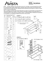
Assembly (Figure 2)
7
Always disconnect the power cord before
assembling the StitchMaster or making any adjustments.
!
CAUTION
!
Assemble the components of the StitchMaster as needed. Use Figure 2 for part number reference.
The Wire Spool Cradle (MG10113) mounts with the two (2) screws (UA3804.7) on the top of the
cover(MG10044B).Usethesupplied1/8”HexKeyWrench(PG10293)toremovethescrewsand
then secure the Cradle to the Cover. The Wire Spool (25G5 or 2125G5) comes assembled on the
Spool Shaft (MG10110) which slips into the slots in the cradle. Pay attention to the payoff direction
of the wire, see Figure 2, so that it matches the above drawing.
Figure 2 - Assembly
MG10110
25G5 OR 2125G5
UA3804.7 (2)
MG10113
MG10009A
MG10001A
MG10044B
MG10097
MG10052A
MG10063
MG10098
PG10248
MG10091A
PG10247
MG10083A
MG10106A
PG10230
5160
PG10293
PG10246

8
The Wire Guide Spring (MG10009A) slides into the slot in the Wire Guide Spring Bracket
(MG10001A) on the top of the Head located at the front of the machine.
The Foot Switch (PG10230) plugs into the Foot Switch Receptacle (PG10226) which is located in
the rear of the machine.
The Rear Work Table (MG10091A) mounts to the rear of the Clincher Arm (MG10052A) using a
Rear Table Pivot Pin (PG10247) and a Table Pivot Pin Clip (PG10248). Pay attention to the direction
of the Pivot Pin Clip to avoid hitting the Trip Switch Assembly (MG10106A). Assemble the Front
Table (MG10083A) to the Clincher Plate Mounting Block (MG10063) after pulling the Adjustment
Handle (MG10097) to the left and out of the way. The Adjustment Nut (MG10098) should spring
into one of the two holes in the bottom of the right pivot plate on the Front Table. The hole chosen
determines whether the StitchMaster will be set up for Flat or Saddle Stitching. Slide a Clevis Pin
(PG10247) into the hole in the top of the Front Table, through the Clincher Plate Mounting Block
(MG10063) and out the other side. Secure the Clevis Pin with a Table Pivot Pin Clip (PG10248) to
keep it in position.
The Trip Switch Assembly (MG10106A) mounts in the slots on the Rear Work Table (MG10091A)
after removing the Lock Nut (MG10105) and the Lock Nut Washer (P2126). Refer to Figure 3 for
the Trip Switch mounting. If positioned correctly, the Trip Switch Assembly should use the mounting
or right slot on the back of the table and the fingers of the Trip Lever (MG10100) should be visible
through the two center slots. Once the Trip Switch Assembly is in place, replace the washer and the
lock nut. After the assembly is completed, the entire assembly should slide freely front to back when
the lock nut is loosened and remain in place when it is tightened.
Plug the Trip Switch Plug
Assembly (MG10049A)
into the Table Trip Jack
(PG10227) on the
under-
side
of the machine on the
left.
Once the assembly is com-
plete, turn the machine
over by hand a few times
using the Shaft Extension
Handle (PG10211) located
at the rear of the unit. All
parts must operate free-
ly before turning on the
power. Push and turn the
handle counter-clockwise (looking from the rear of the machine) to manually rotate the machine. You
are ready to plug in your StitchMaster, but do not turn on the main power yet.
Figure 3 - Trip Switch Assembly
MG10091A
MG10105
P2126

Wire Straightening (Figure 5)
Before the machine is turned on, disengage the
Swivel Operating Spring (9046A) and remove the
Swivel Assembly (9038M or 9038A). Thread the
wire from the Spool through the Wire Guide Spring
(MG10009A), between the Wire Straightener Rollers
(9103) and the Wire Straightener Bushing (9065)
on the Wire Guide Spring Bracket (MG10001A)
as well as between the Wire Straightener Bushing
and the Wire Straightener Rollers on the Face Plate
(2132BA). Continue to pull the wire through the
Tension Pawl (9098) and through the hole in the
Face Plate, in the top of the Wire Cutter (9048)
Holder and through the Swivel Holder (9043B).
At this point, do not worry if the wire is not fed
between the Grip (9015) and the Grip Holder area.
Note: The Tension Pawl will hold the wire in
the groove in the Wire Straightener Roller (9103).
This will allow the wire to feed through the Head
but not allow it to “back-up.”
Pull enough wire through the bottom of the
Head to clear away what was bent in the threading
process. With the Swivel still removed, power the
StitchMaster on and switch the Trip Mode Switch
(PG10232), found on the back of the Machine, to
single mode stitching. Trip either the Foot or the
Hand switch to allow the wire to automatically
thread between the Grip and the Grip Holder. This
will also cut off any excess wire below the Cutters.
9
Figure 4 - Wire Threading
Operation
Wire Threading (Figure 4)
Wire straightness is important so that the stitches are loaded, driven and clinched properly. Although
straightness is set at the factory, every roll of wire has varying degrees of twist which makes it neces-
sary for the user to properly straighten the wire prior to production. Easy steps for straightening the
wire are listed below.
MG1009A
MG10001A
9065
2132BA
9046A
9103
9098
9015
9048 (2)
9043B
9038M or
9038A
9103 (2)

10
Switch the Trip Mode Switch (PG10232), found on the back
of the Machine, to continuous stitching and activate the Foot
Switch (PG10230). Watch the feeding of the Wire through the
Swivel Holder (9043B) and notice the direction the Wire is
moving. To compensate for some of the Wire Spool’s (25G5
or 21256G5) natural curve, the wire optimally should be feed-
ing slightly to the right. Use the Wire Straightener Eccentric
Nut (9067) on the Face Plate (2132BA) to adjust the wire.
Right-to-Left Adjustment
Look through the Swivel Holder (9043B) at the Wire being
fed through the Head. If the Wire is feeding to the left or per-
fectly straight up and down, adjust the Wire Straightener Nut
(9067) so that the Wire Straightener Pointer (9070) turns coun-
ter-clockwise. Remember, the StitchMaster works optimally if
the Wire curves slightly to the right. Allow enough Wire to
be fed through the Head so that an accurate assessment can
be made. After an adjustment is made it takes approximately
four to six stitches to take effect. If the Wire is feeding too far
to the right, adjust the Wire Straightener Nut so that the Wire
Straightener Pointer turns clockwise.
Front-to-Back Adjustment
Look at the Wire feeding through the Head from the side
and make sure that it is straight front-to-back. The Wire
Straightener Eccentric (9067) on the Wire Guide Spring
Bracket (MG10001A) adjusts the curve if it is not straight. Setting the Wire Straightener Pointer
(9070) at a position comparable to 7:00 on the face of a clock is a good place to start. If the Wire
is feeding too far to the front, adjust the Wire Straightener Eccentric so that the Wire Straightener
Pointer turns clockwise. Allow enough Wire to be fed through the Head, about four to six stitch-
es, to make an accurate assessment. If the Wire is feeding too far to the back, adjust the Wire
Straightener Eccentric so that the Wire Straightener Pointer turns counter-clockwise.
Figure 5 - Wire Straightening
Make sure the Swivel has been removed
before tripping the StitchMaster to avoid
jams and the chipping of parts.
WARNING
!
MG10001A
9070
9067
9067
2132BA
9043B

Adjusting the Length of the Left Leg (Figure 6)
11
Once the StitchMaster has been threaded and the wire straightness has been obtained, it is time
to begin stitching. Replace the Swivel Assembly (9038M or 9038A) and secure it with the Swivel
Operating Spring (9046A). Set the Trip Mode Switch (PG10232), found on the back of the Machine,
to single stitching.
Note: The continuous Trip Mode is used primarily for oiling
and wire straightness adjustment.
Activate the Trip (MG10106A) or Foot
Switch (PG10230) once to load a piece of
wire into the Swivel. Even though the
StitchMaster has been tested at the factory, the
wire draw adjusted and the legs equalized, the
following are directions to make these adjust-
ments if necessary. One control, the Face
PlateAdjustment Knob (MG10013) controls
both the length of the left leg and wire draw.
Adjusting the Stitch’s Left Leg
If after a few stitches, the length of the
stitch’s left leg is too short compared to
that of the right, you will need to adjust
the Face Plate (2132BA). Loosen the Wire
Guide Spring Bracket Screw (9075) found
on the side of the Head. Turn the Face Plate
Adjustment Knob clockwise and tighten the
screw. If the length of the left leg is too long,
loosen the Wire Guide Spring Bracket Screw
and turn the Face Plate Adjustment Knob
counter-clockwise. After the length of the
stitch’s left leg is satisfactory make sure to
tighten the screw again.
Figure 6 - Adjusting the Left Leg and Wire Draw
Do not operate the StitchMaster Stitcher
until all guards are in place
!
CAUTION
!
9075
MG10013
9799
9046A
2132BA
2601R
9015
9038A or
9038M

The overall length of the stitch is controlled
by the amount of wire that is drawn from the
spool after each stroke of the StitchMaster.
To change the overall length of the stitch,
loosen the Face Plate Adjusting Lock Screw
(9799) on the front of the Head. Turn the
Face Plate Adjustment Knob clockwise to
raise the Face Plate which draws more wire -
making the overall length of the stitch longer.
If the overall length is too long, turn the Face
PlateAdjustmentKnobcounter-clockwiseto
lower the Face Plate and decrease the draw
of wire pulled from the Wire Spool. Once
the correct length of wire has been achieved,
tighten the Face Plate Adjusting Lock Screw.
As a rough gauge, the distance the Face Plate
is above the Bonnet (2601R) should be equal
to the work thickness.
Note: If the Face Plate is adjusted too high
(turning the Face Plate Adjustment Knob too
far clockwise) the Grip (9015) will lock in an
open position and draw no more wire. The
StitchMaster has a capacity of 1/4” and will
allow no more than that amount of wire to be
drawn from the spool.
Adjusting the Wire Draw (Figure 6)
Figure 7 - Adjusting the Clincher Points
Always disconnect the power cord before
making any adjustments or servicing the StitchMaster
WARNING
!
12
MG10067
MG10072
MG10070
MG10020BA
MG10031A
9009-25 or
9009-21X25
9083A OR
9083C
9800A or
9800B
MG10062

13
Adjusting the Clincher Points (Figure 7)
Note: The standard StitchMaster accepts only 25 gauge and smaller round wire. If other wire sizes
are required contact your local DeLuxe Stitcher Graphic Arts Representative for information.
If the clinch on the staple is not tight enough, the Clincher Points (9083A or 9083C) have to be
raised. The Clincher Rod (MG10070) controls the height of the Clincher Points. First remove
the Cover (MG10044B) from the Frame (MG10020BA). Release the Clincher Rod from the Cam
Lever (MG10067) by pressing down on the bend of the Clincher Rod. Turn the Clincher Rod Stud
(MG10072) clockwise to lower the Clincher Slide (MG10062), which lowers the Clincher Points.
Engage the Clincher Rod with the Cam Lever again to test the clinch. If the Clincher Points are too
low, adjust the Clincher Rod Stud counter-clockwise to raise the Clincher slide, which in turn raises
the Clincher Points. Be sure to always re-insert the Clincher Rod and Clincher Rod Stud into the Cam
Lever before testing the height of the Clincher Points.
The final position of the Clincher Points should be flush (or slightly above flush) with the Clincher
Plate (9800A). The best way to see the position of the Clincher Points is to manually turn the
StitchMaster over. When the Driver (9009-25 or 9009-21x25) is at the lowest position of its stroke,
the Clincher Points are at their highest position. Turn the Crank (MG10031A) just past this point to
reveal the Clincher Points’ position. To be sure that the Points are at the best position possible, test
the StitchMaster after turning the Clincher Rod Stud 1/2 turn each way. Replace the Cover.
Note: This adjustment is very sensitive - one half turn should affect the clinching considerably.
Do not operate the StitchMaster Stitcher
until all guards are in place
!
CAUTION
!

14
Stitching Process
The StitchMaster has been designed to accommodate a variety of jobs. For this reason, adjustable
work tables and work stops have been installed on the StitchMaster. The following is a brief explana-
tion of the options available on the machine.
Pull the Table Adjustment Handle to the left and lift the Front Work Table to the flat position. Pull
the Rear Work Table up until the spring pops into the holes in the back of the Front Work Table.
Note: You may have to push the springs, slightly to clear the Front Table. (see Figure 8)
Push the Springs back into the holes in the underside of the Front Table (MG10083A) with your
thumbs, allowing the Rear Work Table (MG10091A) to drop out of the way. Be sure that the Trip
Switch Assembly (MG10106A) is adjusted just inside the Rear Work Table so that it does not hit the
Front Work Table or the Clincher Arm (MG10052A) as the Rear Work Table is lowered. After the
Rear Work Table is out of the way, pull the Table Adjustment Handle (MG10097) to the left and drop
the Front Work Table into the saddle position.
Saddle Stitching (Figure 8)
Flat Stitching (Figure 8)
Figure 8 - Saddle and Flat Stitching
MG10091A
MG10083A
MG10106A
MG10097
MG10052A
SPRING
SPRING

Corner Stitch Stops are applicable to flat work only. Push the Corner Stitch Pins (PG10242) up
from the bottom of the Front Work Table (MG10083A) until they lock into place. One or both of the
Corner Stops may be used to locate the accurate stitch position.
Corner Stitch Stops (Figure 9)
15
Figure 9 - Side and Corner Stops
Loosen the Stop Rod Screws (PG10243) on the front of the Front Work Table (MG10083A) and
slide the Left and Right Side Stops (MG10081 and MG10082) out to the necessary distance from the
Stitcher Head to position the work under the StitchMaster where you will stitch.
Side Stops (Figure 9)
The Solid Backstop is an optional assembly which can be ordered from your DeLuxe Stitcher
GraphicArtsRepresentative-ordertheSMK2BackstopKit.TheBackstopismountedontheRear
Table of your StitchMaster and locates the depth of the stitch.
Solid Backstop
PG10242
MG10083A
MG10081
PG10243
MG10082

The Stitch Mode Switch (PG10232) is found on the back of the StitchMaster. (The switch on the left,
looking from the rear of the machine.) There are two modes; single or continuous stitching. Single
stitching is used for production. In the single trip mode only one stitch will be released at a time, no
matter how long the trip switches are activated, whereas the continuous stitch mode the machine will
continue to deliver stitches as long as one of the trip switches is activated. The continuous stitch mode
is used only for testing and trouble-shooting.
The Trip Switch Assembly only
works for flat stitching. Loosen the
Lock Nut (MG10105) and slide the
Trip Switch Assembly (MG10106A),
front or back to the desired position on
the Rear Work Table (MG10091A).
Use the Backstop Gauge Sticker
(PG10214) on the Rear Work Table
as a guide. When the correct locating
position has been determined, tighten
the lock nut.
Trip Switch (Figure 10)
Stitch Mode
The Trip Mode Switch (PG10232) is also found on the back of the StitchMaster. (The switch on the
right, looking from the rear of the machine.) Either the foot trip or the table trip mode can be selected.
The table trip mode or Trip Switch Assembly (MG10106A) can be used only for flat work. The Trip
Switch Assembly plugs into the underside of the StitchMaster, on the left. For all saddle stitch work
the foot trip mode must be used. Be sure that the Foot Switch (PG10230) is plugged into the rear of
the StitchMaster and the Trip Mode Switch is toggled for this mode.
Trip Mode
16
Figure 10 - Trip Switch
MG10105
MG10106A
MG10091A
PG10214

Trouble Shooting (Figure 11)
The following is a brief list of problems and solutions which should cover the majority of situations
encountered when stitching with the StitchMaster. Most problems with stitches are due to incorrect
adjustments on the machine or to the normal wear of parts.
17
problem: The machine does not cycle and the Main Power Switch (PG1022B) is on.
solution: Make sure the Power Cord (P2581 or PG10410) is properly plugged into a live receptacle.
Check to see if the Circuit Breaker (PG10234 or PG10406) has been tripped. If so, push it to reset. If
it still does not cycle, make sure the Foot Switch (PG10230) or Trip Switch Assembly (MG10106A) is
plugged in and the corresponding Trip Switch position is selected. The Head Guard (PG10003) must
be in place to fully depress the safety interlock, otherwise the StitchMaster will not function.
Note: if the Head Guard moves enough to lose contact with the Safety Switch (PG10229) the Head
Guard must be rotated upward to clear the Safety Switch and re-closed.
Figure 11 - Troubleshooting
problem: Right Leg Short
solution: Shorten the left leg and then lengthen both of the stitch’s legs.
(See pages 11 - 12)
problem: Left Leg Short
solution: Lengthen the left leg. Check the Grip for wear and rotate or
replace it if needed. (See pages 11 and 12)
problem: Corner Buckled
solution: Check the Driver for a chipped corner and rotate or replace it
if needed. (See pages 25 and 26)
problem: Leg(s) Buckled
solution: Check the Wire Cutters for wear and rotate or replace if needed.
(See pages 23 and 24)
Do not operate the StitchMaster Stitcher
until all guards are in place
!
CAUTION
!

problem: Crown Buckled
solution: Check Supporter Spring (9032) tension. If it is too loose
adjust it.
problem: Stitch in Pieces
solution: Clean and lubricate the Swivel. (See page 21)
problem: Corners of the Crown are Rounded
solution: Replace the worn Swivel.
problem: Loose Clinch
solution: Raise the Clincher Points. (See pages 13 and 14)
problem: Legs are Spread or Contracted
solution: Readjust the Wire Straightener Eccentrics. (See pages 10 and 11)
Check the Wire Cutters for wear and rotate or replace if needed. (See pages
23 and 24) Check the Bender Bar for wear in the grooves and
replace if needed.
18
Maintenance
Lubrication (Figure 12)
Your StitchMaster has been fully lubricated at the factory, but regular preventative maintenance
will result in superior performance and longer life of the machine. A good rule of thumb is to oil the
StitchMaster’s critical points every five pound wire spool change or every month, whichever comes
first. Use one drop of any standard S.A.E #10 oil in the following lubrication points:
Figure 11 - Troubleshooting
Always disconnect the power cord
before any maintenance or adjustments are
made to the StitchMaster
!
CAUTION
!

In addition to proper lubrication, routine cleaning is important for the maintenance of your
StitchMaster. The following areas should be cleaned every three months:
•Swivel Assembly (9038M or 9038A): remove and wash in an oil-dissolving solvent, dry
and relubricate.
•Swivel Holder (9043B): clean inside the Swivel hole.
•Swivel Operating Lever and Stud: remove the Swivel Operating Spring (9046A) and
Lever (9163). Clean the Swivel Operating Spring Stud (9129B) and the holes in the Lever,
relubricate and replace.
Note: Use care when replacing the Swivel Operating Lever to avoid serious damage being
done to the head.
•Anywhere that dust, oil or pieces of wire and paper have built up - for example: the Grip,
Clincher Points and around the Wire Straightener Rollers.
Cleaning (Figure 12)
19
•atthetopoftheBonnet(2601R)on
either side of the Wire Guide Spring
Bracket (MG10001A)
•theoilholeintheSwivelOperating
Hub (9163)
•theoilholesintheFacePlate(2132BA)
•ontheBenderBarLatch(9014)andon
the Grip (9015)
•theoilholeintheDrivingShaft
Connection Link (2215)
•theopeningintheSwivelHolder
(9043B)
• where the Clincher Points (9083A or
9083C) pivot
•theWireCutterOperatingSlideslot
(9049)
•ontheWireStraightenerRolls(9065)
and Tension Pawl (9098)
Figure 12 - Lubrication and Cleaning
9046A
9129B
9163
9043B
9038A or
9038M
9065
9098
2132BA
9049
2215
9083A or
9083C
9014
9015
MG10001A

20
In time, you will need to replace some parts in your StitchMaster. When this happens, first locate the
needed part in one of the following diagrams. Then locate the DeLuxe Stitcher part number and con-
tact your Graphic Arts Representative to order the part by the part number, description and quantity.
Ordering Spare Parts
Replacing Spare Parts
The following are some
of the more common wear
parts which will need to be
removed and replaced in
your StitchMaster. Most
replacements require the
Stitcher Head to be removed
from the StitchMaster. This
explanation and instructions
to do so will be given first,
then a more specific descrip-
tion for each common wear
part will follow.
General Maintenance
and Repair (Figure 13)
While some adjustments
can be made to the
StitchMaster and the stitcher
head, most maintenance and
general repairs have to be
made with the stitcher head
removed from the machine.
Cut the wire from the
wire spool just below the
Wire Guide Spring Bracket
(MG10001A).
Figure 13 - Removing & Disassembling the Stitcher Head
Always disconnect the power cord
before any maintenance or adjustments are
made to the StitchMaster
!
CAUTION
!
MG10001A
MG10011A
9115
2137A
9012A
9075
9014
9015
9023
2132BA
9003A
0084
UA2305.2
9050B
9049
9026A
9013BA-25 or
9013BA-21X25
9009-25 or
9009-21X25
9022
/