Page is loading ...
OperatingGuide
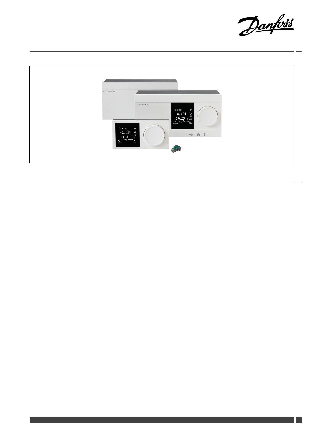
ECLComfort310,applicationP318
1.0TableofContents
1.0TableofContents...............................................1
1.1Importantsafetyandproductinformation.....................2
2.0Installation........................................................6
2.1Beforeyoustart.....................................................6
2.2Identifyingthesystemtype......................................18
2.3Mounting...........................................................19
2.4Placingthetemperaturesensors................................23
2.5Electricalconnections.............................................25
2.6InsertingtheECLApplicationKey..............................31
2.7Checklist............................................................37
2.8Navigation,ECLApplicationKeyP318.........................38
3.0Dailyuse.........................................................46
3.1Howtonavigate...................................................46
3.2Understandingthecontrollerdisplay..........................47
3.3Ageneraloverview:Whatdothesymbolsmean?...........48
3.4Monitoringtemperaturesandsystem
components........................................................49
3.5Manualcontrol.....................................................50
3.6Schedule............................................................51
4.0Settingsoverview............................................52
5.0Settings...........................................................54
5.1IntroductiontoSettings..........................................54
5.2Tanktemperature..................................................55
5.3Flowtemperature..................................................59
5.4Returnlimit.........................................................61
5.5Controlparameters................................................65
5.6Flowmeter..........................................................75
5.7Application.........................................................76
5.8Anti-bacteria........................................................78
6.0Event...............................................................80
6.1IntroductiontoEvent.............................................80
6.2ChargeT.............................................................81
6.3DHWowT.........................................................84
6.4Tanktemperature..................................................87
6.5SupplyT.............................................................90
6.6Anti-bacteria........................................................91
6.7Tsensordefect.....................................................92
6.8Eventoverview.....................................................93
7.0Commoncontrollersettings..............................94
7.1Introductionto‘Commoncontrollersettings’................94
7.2Time&Date.........................................................95
7.3Inputoverview.....................................................96
7.4Log...................................................................97
7.5Outputoverride....................................................98
7.6Keyfunctions.......................................................99
7.7System.............................................................101
8.0Miscellaneous................................................108
8.1ECA30/31setupprocedures.................................108
8.2Severalcontrollersinthesamesystem......................116
8.3Frequentlyaskedquestions....................................119
8.4Denitions........................................................121
8.5Type(ID6001),overview.......................................124
8.6ParameterIDoverview..........................................125
DanfossDistrictEnergy
VI.JM.Q3.02
DEN-SMT/DK1

OperatingGuideECLComfort310,applicationP318
1.1Importantsafetyandproductinformation
1.1.1Importantsafetyandproductinformation
ThisOperatingGuideisassociatedwiththeECLApplicationKey
P318(codeno.087H3835).
TheECLApplicationKeyP318containstwosubtypes:
•P318.1,whichisabuffer-basedDomesticHotWater(DHW)
application.
•P318.10,whichisanadvancedDomesticHotWater(DHW)
application.
SeetheInstallationGuideforelectricalconnections.
ThedescribedfunctionsarerealizedinECLComfort310whichalso
allowsM-bus,ModbusandEthernet(Internet)communication.
TheApplicationKeyP318complieswithECLComfort310
controllersasofrmwareversion1.11.Thermware(controller
software)isvisibleatstart-upofthecontrollerandin'Common
controllersettings'in'System'.
UptotwoRemoteControlUnits,ECA30orECA31,canbe
connected.
TheapplicationP318workswithadditionalInternalI/Omodules:
•TheextensionmoduleECA32gives0-10Voltsignalforspeed
controlofcontrolpump,chargingpumpandcirculationpump.
•TheextensionmoduleECA35gives0-10Voltsignalforspeed
controlofcontrolpump,chargingpumpandcirculationpump.
ECA35canalsogivePWM*signalforspeedcontrolofthe
abovelistedpumptypes.
Apumpcanalsobeconsideredasacirculator.
TheECLComfort310workswitheitheroneECA32oroneECA
35.TheInternalI/Omoduleinquestionisplacedinthebasepart
oftheECLComfort310.
*PWM=PulseWidthModulation
TogetherwiththeECLComfort310theadditionalInternalI/O
modulescanalsobeusedforextradatacommunicationtoSCADA:
•Temperature,Pt1000(default)
•0-10voltsignals
•Digitalinput
Theset-upofinputtypecanbedonebymeansoftheDanfoss
Software"ECLTool".
Navigation:Danfoss.com>Products&Solutions>Products>
DistrictHeatingandCooling>Documentation>Tools&Software
>ECLTool.
TheURLis:http://district-heating.danfoss.com/download/tools/
ECLComfort310isavailableas:
•ECLComfort310,230volta.c.(codeno.087H3040)
•ECLComfort310B,230volta.c.(codeno.087H3050)
•ECLComfort310,24volta.c.(codeno.087H3044)
TheB-typehasnodisplayanddial.
2
DEN-SMT/DK
VI.JM.Q3.02
DanfossDistrictEnergy
OperatingGuideECLComfort310,applicationP318
TheB-typeisoperatedbymeansoftheremotecontrolunit
ECA30/31:
•ECA30(codeno.087H3200)
•ECA31(codeno.087H3201)
InternalI/Omodules:
•ECA32(codeno.087H3202)
•ECA35(codeno.087H3205)
BasepartforECLComfort310,230voltand24volt:Codeno.
087H3230.
AdditionaldocumentationforECLComfort210and310,modules
andaccessoriesisavailableonhttp://heating.danfoss.com/.
SafetyNote
Toavoidinjuryofpersonsanddamagestothedevice,itisabsolutely
necessarytoreadandobservetheseinstructionscarefully.
Necessaryassembly,start-up,andmaintenanceworkmustbe
performedbyqualiedandauthorizedpersonnelonly.
Locallegislationsmustberespected.Thiscomprisesalsocable
dimensionsandtypeofisolation(doubleisolatedat230V).
AfusefortheECLComfortinstallationismax.10Atypically.
TheambienttemperaturerangesforECLComfortinoperationare:
ECLComfort210/310:0-55°C
ECLComfort296:0-45°C.
Exceedingthetemperaturerangecanresultinmalfunctions.
Installationmustbeavoidedifthereisariskforcondensation(dew).
Thewarningsignisusedtoemphasizespecialconditionsthatshould
betakenintoconsideration.
Thissymbolindicatesthatthisparticularpieceofinformationshould
bereadwithspecialattention.
Applicationkeysmightbereleasedbeforealldisplaytextsare
translated.InthiscasethetextisinEnglish.
DanfossDistrictEnergy
VI.JM.Q3.02
DEN-SMT/DK3
OperatingGuideECLComfort310,applicationP318
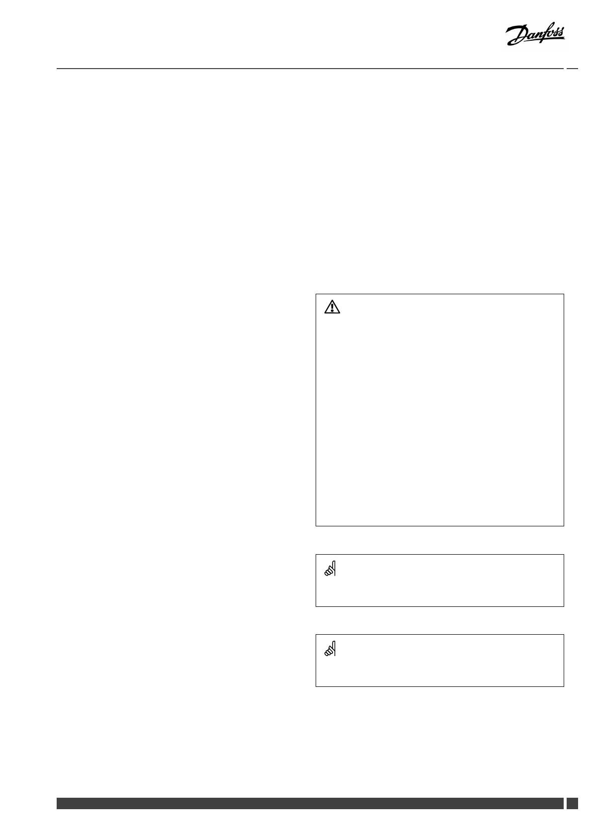
Automaticupdateofcontrollersoftware(rmware):
Thesoftwareofthecontrollerisupdatedautomaticallywhenthekey
isinserted(asofcontrollerversion1.11(ECL210/310)andversion
1.58(ECL296)).Thefollowinganimationwillbeshownwhenthe
softwareisbeingupdated:
Progressbar
Duringupdate:
•DonotremovetheKEY
Ifthekeyisremovedbeforethehour-glassisshown,youhave
tostartafresh.
•Donotdisconnectthepower
Ifthepowerisinterruptedwhenthehour-glassisshown,the
controllerwillnotwork.
AsthisOperatingGuidecoversseveralsystemtypes,specialsystem
settingswillbemarkedwithasystemtype.Allsystemtypesareshown
inthechapter:'Identifyingyoursystemtype'.
°C(degreesCelsius)isameasuredtemperaturevaluewhereasK
(Kelvin)oftenisusedfortemperaturedifferences.
TheIDno.isuniquefortheselectedparameter.
ExampleFirstdigitSeconddigitLastthreedigits
1117411174
-
Circuit1
Parameterno.
12174
1
2
174
-
Circuit2
Parameterno.
IfanIDdescriptionismentionedmorethanonce,itmeansthatthere
arespecialsettingsforoneormoresystemtypes.Itwillbemarked
withthesystemtypeinquestion(e.g.12174-A266.9).
ParametersindicatedwithanIDno.like"1x607"meanauniversal
parameter.
xstandsforcircuit/parametergroup.
4DEN-SMT/DK
VI.JM.Q3.02
DanfossDistrictEnergy

OperatingGuideECLComfort310,applicationP318
DisposalNote
Thisproductshouldbedismantledanditscomponents
sorted,ifpossible,invariousgroupsbeforerecycling
ordisposal.
Alwaysfollowthelocaldisposalregulations.
DanfossDistrictEnergy
VI.JM.Q3.02
DEN-SMT/DK
5
OperatingGuideECLComfort310,applicationP318
2.0Installation
2.1Beforeyoustart
TheECLapplicationkeyP318containstwosubtypes,P318.1and
P318.10.
ThebasicprinciplesforapplicationP318.1:
TemperaturecontrolofDHWbuffer
ThedesiredDHWtemperatureatS6determinesthebuffercharging
procedure.ThebuffertemperaturesensorsS6andS8,thesupply
temperaturesensorS2andthechargingtemperaturesensorS3are
themostimportantsensorsandmustbeconnected.Ifoneofthe
mentionedtemperaturesensorsisnotconnected,thecontrolvalve
M1willclose;alternatively,thecontrolpumpP1/V1willstop.
ThechargingtemperatureatS3isbasedonthedesiredDHW
temperatureatS6andasetchargingdifference.
TheapplicationallowsinternalorexternalDHWcirculation.When
connectedforexternalcirculation,thedesiredS3temperatureis
thesameasthedesiredDHWtemperature,whenchargingisnot
inprogress.
Optional:TemperaturecontrolofthecirculationpipeatS9ensures
thedesiredtemperaturebymeansofON/OFFcontrolofP3or
speedcontrolofV3.Duringthechargingprocessthecirculation
pumpcanbeswitchedOFForrunataminimumspeed.
Startbufferchargingprocess:
1.BuffertemperatureS6temperaturegetslowerthan('Desired
DHWtemperature'+'Startdifference').
Anexample:60°C+(-5)=55°C
2.X1isswitchedON
3.M1openstoapresetposition(alternatively,P1/V1isswitched
ON/presetspeed)inordertoincreasethesupplytemperature
S2.Returntemperaturelimitationisrespected.
4.P2/V2isswitchedONwhensupplytemperatureS2getshigher
than('DesiredDHWtemperature'+'Pumpstartdiff.').
Anexample:60°C+3K=63°C
V2startswithminimumspeed,forexample20%.
5.M1(orP1/V1)controlsthechargingtemperatureatS3.
6.V2increasesthespeedaslongasthechargingtemperatureS3
ishigherthan(desiredchargingtemperature-2K).
Stopbufferchargingprocess:
1.BuffertemperatureS6temperaturegetshigherthan(2K+
'DesiredDHWtemperature'+'Startdifference)
AND
LowerbuffertemperatureS8getshigherthan('DesiredDHW
temperature'+'Stopdifference).
Anexample:S6temperaturehigherthan(2+60°C+(-5)=
57°C)AND(60°C+(-8)=52°C)
2.P2isswitchedOFF,respecting'Char.Ppost-run'.V2changes
to0%.
NOTE:Post-runisnotrespectedifchargingtemperatureS3islower
thandesiredchargingtemperature.
3.X1isswitchedOFF.
4.M1closes(alternatively,P1/V1stops)ormaintainsthedesired
temperatureatS3.
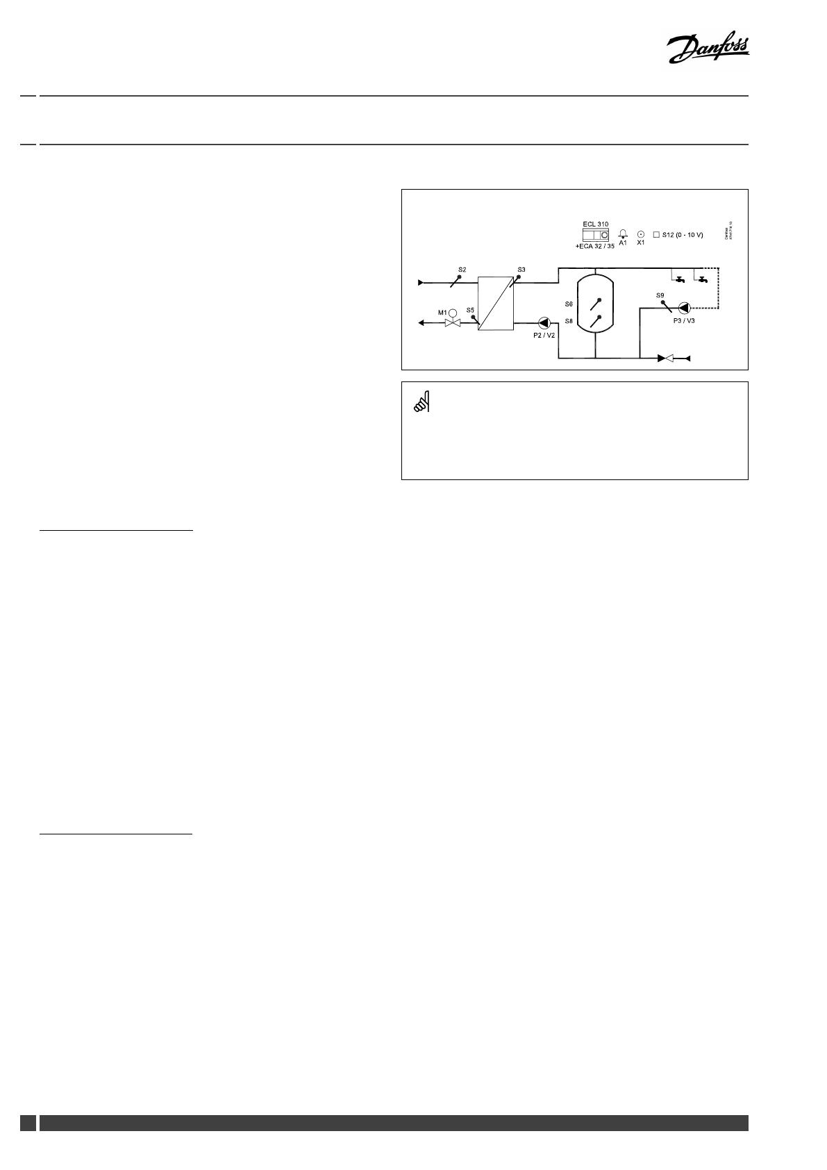
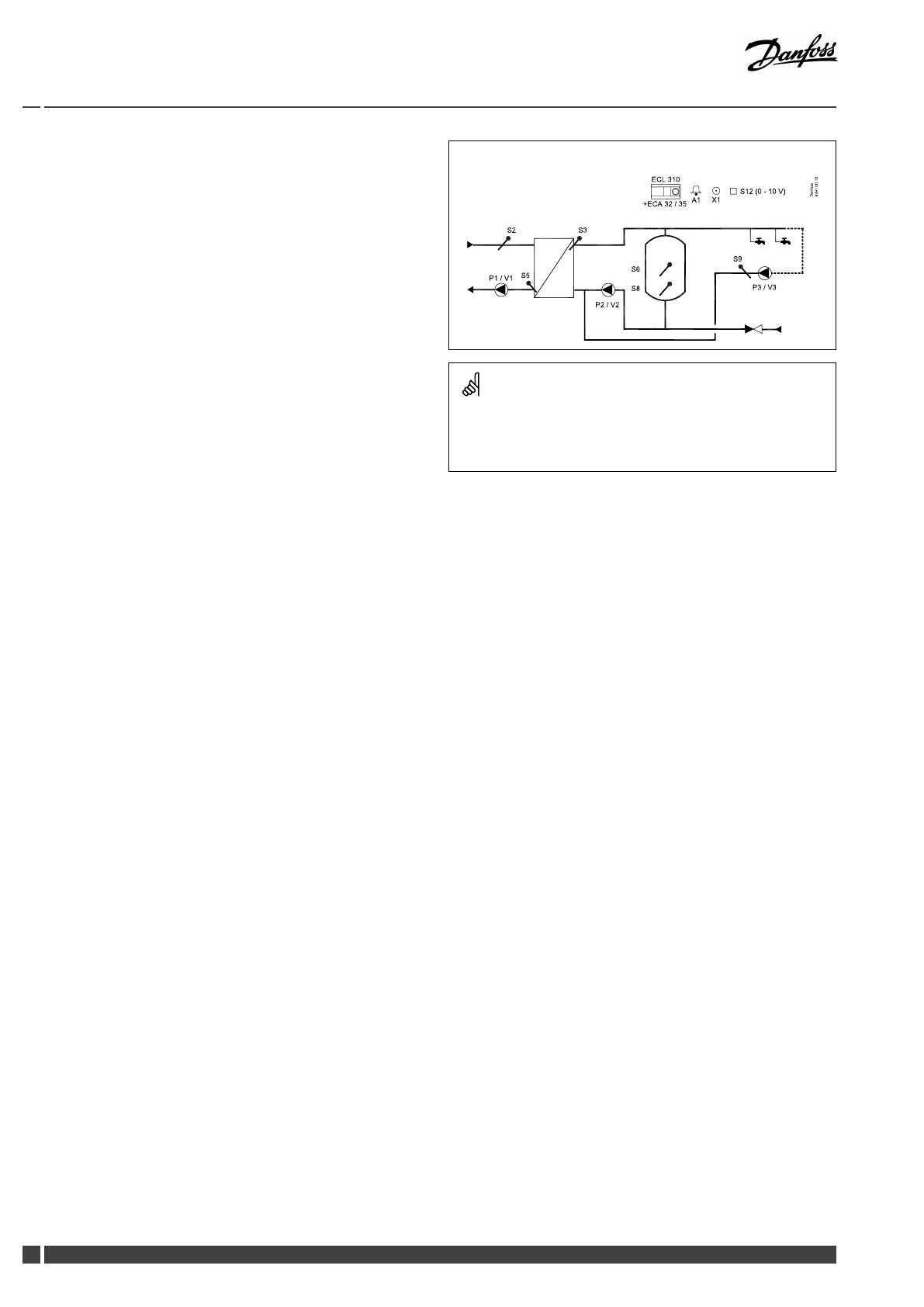
P318.1,ex.a,applicationwithcontrolvalveandinternalDHWcirculation:
Theshowndiagramisafundamentalandsimpliedexampleanddoes
notcontainallcomponentsthatarenecessaryinasystem.
AllnamedcomponentsareconnectedtotheECLComfortcontroller.
Listofcomponents:
ECL310
ECLComfort310controller
ECA32
Built-inextensionmodule,0-10Voutputs
ECA35
Built-inextensionmodule,0-10Voutputsand
PWMoutputs
S2
(mandatory)Supplytemperaturesensor
S3
(mandatory)Chargingtemperaturesensor
S5
Returntemperaturesensor
S6
(mandatory)Buffertemperaturesensor
S8
(mandatory)Lowerbuffertemperaturesensor
S9
DHWcirculationreturntemperaturesensor
S12
0-10VinputfordesiredtemperatureatS6
P2
Chargingpump(ON-OFFcontrolled)
V2
Speedcontrolofchargingpump(0-10VorPWM)
P3
Circulationpump(ON-OFFcontrolled)
V3
Speedcontrolofcirculationpump(0-10Vor
PWM)
M1
Motorizedcontrolvalve(3-pointcontrolled)
X1
Heatdemandsignal
A1
Alarm
6DEN-SMT/DK
VI.JM.Q3.02
DanfossDistrictEnergy

OperatingGuideECLComfort310,applicationP318
Bymeansofaweekschedule,theDHWcirculationcanbeON/
OFFcontrolled.
ThemotorizedcontrolvalveM1isopenedgraduallywhen
thechargingtemperatureislowerthanthedesiredcharging
temperatureandviceversa.
Alternatively,thecontrolpumpP1/V1isincreasedinspeedwhen
thechargingtemperatureislowerthanthedesiredcharging
temperatureandviceversa.
ThereturntemperatureS5canbelimited,forexamplenottobe
toohigh.Ifso,thedesiredchargingtemperatureatS3canbe
adjusted(typicallytoalowervalue);thisresultsinagradualclosing
ofthemotorizedcontrolvalveor,alternatively,alowerspeedof
thecontrolpump.
TheON-OFFoutputX1isONatDHWheatingdemand.
Asanoption,thedesiredDHWtemperaturecanbesetexternally.
Avoltagesignal(1-10Volt)canbeappliedtoinputS12(ECA32/
35).Thescaleforvoltageversustemperaturecanbeset.
Ananti-bacteriafunctionfortheDHWbufferisavailablefor
activationonselecteddaysoftheweek.
Theanti-bacteriafunctioncanbesettoincludetheDHW
circulation.
DanfossDistrictEnergy
VI.JM.Q3.02
DEN-SMT/DK7

OperatingGuideECLComfort310,applicationP318
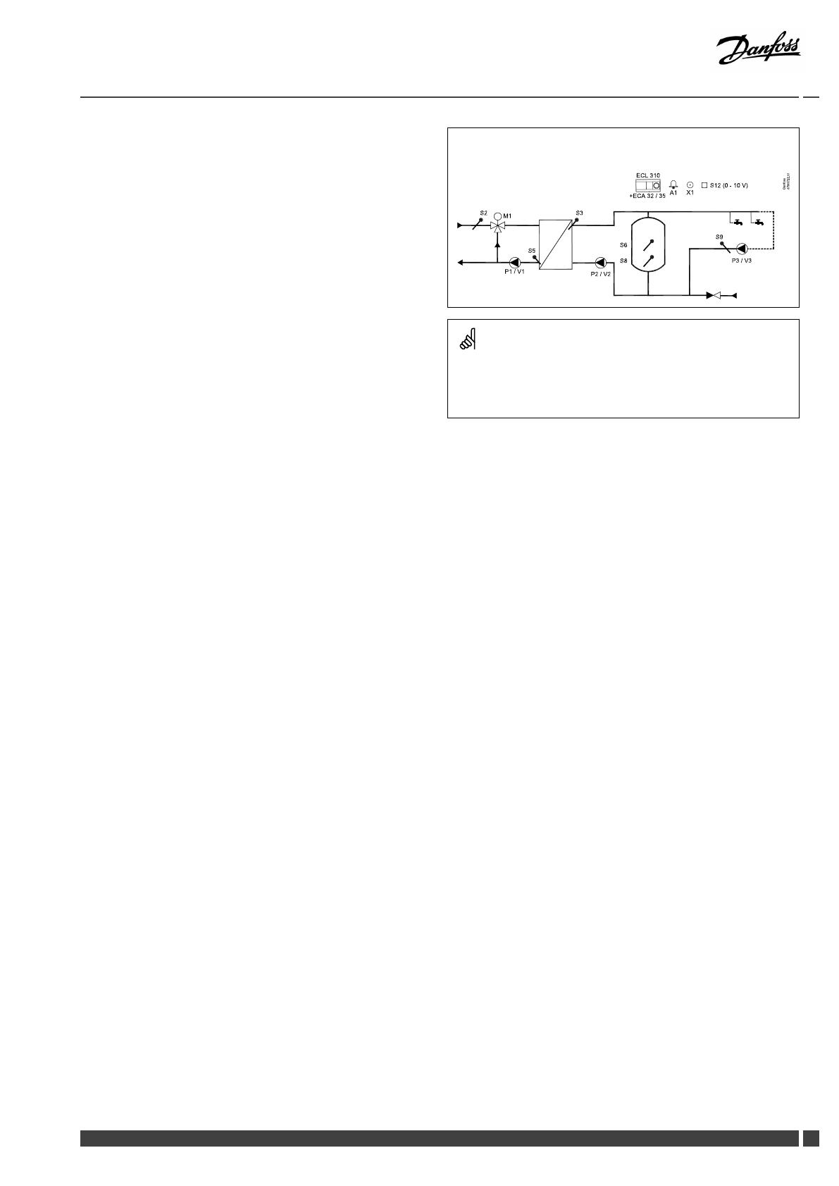
P318.1,ex.b,applicationwithcontrolvalveandexternalDHWcirculation:
Theshowndiagramisafundamentalandsimpliedexampleanddoes
notcontainallcomponentsthatarenecessaryinasystem.
AllnamedcomponentsareconnectedtotheECLComfortcontroller.
Listofcomponents:
ECL310
ECLComfort310controller
ECA32
Built-inextensionmodule,0-10Voutputs
ECA35
Built-inextensionmodule,0-10Voutputsand
PWMoutputs
S2
(mandatory)Supplytemperaturesensor
S3
(mandatory)Chargingtemperaturesensor
S5
Returntemperaturesensor
S6
(mandatory)Buffertemperaturesensor
S8
(mandatory)Lowerbuffertemperaturesensor
S9
DHWcirculationreturntemperaturesensor
S12
0-10VinputfordesiredtemperatureatS6
P2
Chargingpump(ON-OFFcontrolled)
V2
Speedcontrolofchargingpump(0-10VorPWM)
P3
Circulationpump(ON-OFFcontrolled)
V3
Speedcontrolofcirculationpump(0-10Vor
PWM)
M1
Motorizedcontrolvalve(3-pointcontrolled)
X1
Heatdemandsignal
A1
Alarm
8DEN-SMT/DK
VI.JM.Q3.02
DanfossDistrictEnergy

OperatingGuideECLComfort310,applicationP318
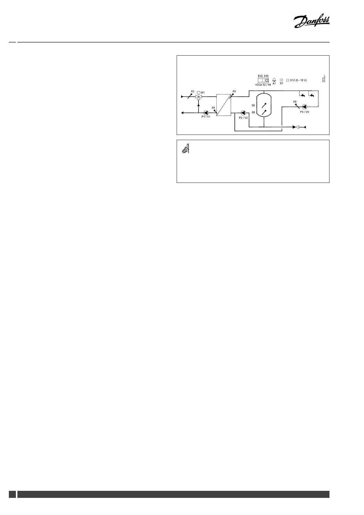
P318.1,ex.c,applicationwithcontrolpumpandinternalDHWcirculation:
Theshowndiagramisafundamentalandsimpliedexampleanddoes
notcontainallcomponentsthatarenecessaryinasystem.
AllnamedcomponentsareconnectedtotheECLComfortcontroller.
Listofcomponents:
ECL310
ECLComfort310controller
ECA32
Built-inextensionmodule,0-10Voutputs
ECA35
Built-inextensionmodule,0-10Voutputsand
PWMoutputs
S2
(mandatory)Supplytemperaturesensor
S3
(mandatory)Chargingtemperaturesensor
S5
Returntemperaturesensor
S6
(mandatory)Buffertemperaturesensor
S8
(mandatory)Lowerbuffertemperaturesensor
S9
DHWcirculationreturntemperaturesensor
S12
0-10VinputfordesiredtemperatureatS6
P1
Controlpump(ON-OFFcontrolled)
V1
Speedcontrolofcontrolpump(0–10VorPWM)
P2
Chargingpump(ON-OFFcontrolled)
V2
Speedcontrolofchargingpump(0-10VorPWM)
P3
Circulationpump(ON-OFFcontrolled)
V3
Speedcontrolofcirculationpump(0-10Vor
PWM)
X1
Heatdemandsignal
A1
Alarm
DanfossDistrictEnergy
VI.JM.Q3.02
DEN-SMT/DK9
OperatingGuideECLComfort310,applicationP318
P318.1,ex.d,applicationwithcontrolpumpandexternalDHWcirculation:
Theshowndiagramisafundamentalandsimpliedexampleanddoes
notcontainallcomponentsthatarenecessaryinasystem.
AllnamedcomponentsareconnectedtotheECLComfortcontroller.
Listofcomponents:
ECL310
ECLComfort310controller
ECA32
Built-inextensionmodule,0-10Voutputs
ECA35
Built-inextensionmodule,0-10Voutputsand
PWMoutputs
S2
(mandatory)Supplytemperaturesensor
S3
(mandatory)Chargingtemperaturesensor
S5
Returntemperaturesensor
S6
(mandatory)Buffertemperaturesensor
S8
(mandatory)Lowerbuffertemperaturesensor
S9
DHWcirculationreturntemperaturesensor
S12
0-10VinputfordesiredtemperatureatS6
P1
Controlpump(ON-OFFcontrolled)
V1
Speedcontrolofcontrolpump(0–10VorPWM)
P2
Chargingpump(ON-OFFcontrolled)
V2
Speedcontrolofchargingpump(0-10VorPWM)
P3
Circulationpump(ON-OFFcontrolled)
V3
Speedcontrolofcirculationpump(0-10Vor
PWM)
X1
Heatdemandsignal
A1
Alarm
10DEN-SMT/DK
VI.JM.Q3.02
DanfossDistrictEnergy
OperatingGuideECLComfort310,applicationP318
P318.1,ex.e:Primarysideisacombinationofa3-portcontrolvalveanda
controlpump.InternalDHWcirculation:
Theshowndiagramisafundamentalandsimpliedexampleanddoes
notcontainallcomponentsthatarenecessaryinasystem.
AllnamedcomponentsareconnectedtotheECLComfortcontroller.
Listofcomponents:
ECL310
ECLComfort310controller
ECA32
Built-inextensionmodule,0-10Voutputs
ECA35
Built-inextensionmodule,0-10Voutputsand
PWMoutputs
S2
(mandatory)Supplytemperaturesensor
S3
(mandatory)Chargingtemperaturesensor
S5
Returntemperaturesensor
S6
(mandatory)Buffertemperaturesensor
S8
(mandatory)Lowerbuffertemperaturesensor
S9
DHWcirculationreturntemperaturesensor
S12
0-10VinputfordesiredtemperatureatS6
M1
Motorized3-portcontrolvalve(3-pointcontrolled)
P1
Controlpump(ON-OFFcontrolled)
V1
Speedcontrolofcontrolpump(0–10VorPWM)
P2
Chargingpump(ON-OFFcontrolled)
V2
Speedcontrolofchargingpump(0-10VorPWM)
P3
Circulationpump(ON-OFFcontrolled)
V3
Speedcontrolofcirculationpump(0-10Vor
PWM)
X1
Heatdemandsignal
A1
Alarm
DanfossDistrictEnergy
VI.JM.Q3.02
DEN-SMT/DK11
OperatingGuideECLComfort310,applicationP318
P318.1,ex.f:Primarysideisacombinationofa3-portcontrolvalveanda
controlpump.ExternalDHWcirculation:
Theshowndiagramisafundamentalandsimpliedexampleanddoes
notcontainallcomponentsthatarenecessaryinasystem.
AllnamedcomponentsareconnectedtotheECLComfortcontroller.
Listofcomponents:
ECL310
ECLComfort310controller
ECA32
Built-inextensionmodule,0-10Voutputs
ECA35
Built-inextensionmodule,0-10Voutputsand
PWMoutputs
S2
(mandatory)Supplytemperaturesensor
S3
(mandatory)Chargingtemperaturesensor
S5
Returntemperaturesensor
S6
(mandatory)Buffertemperaturesensor
S8
(mandatory)Lowerbuffertemperaturesensor
S9
DHWcirculationreturntemperaturesensor
S12
0-10VinputfordesiredtemperatureatS6
M1
Motorized3-portcontrolvalve(3-pointcontrolled)
P1
Controlpump(ON-OFFcontrolled)
V1
Speedcontrolofcontrolpump(0–10VorPWM)
P2
Chargingpump(ON-OFFcontrolled)
V2
Speedcontrolofchargingpump(0-10VorPWM)
P3
Circulationpump(ON-OFFcontrolled)
V3
Speedcontrolofcirculationpump(0-10Vor
PWM)
X1
Heatdemandsignal
A1
Alarm
12
DEN-SMT/DK
VI.JM.Q3.02
DanfossDistrictEnergy

OperatingGuideECLComfort310,applicationP318
ThebasicprinciplesforapplicationP318.10:
TemperaturecontrolofDHW
ThedesiredDHWtemperatureatS3determinesthetemperature
control.
TheDHWowtemperaturesensorS3andtheDHWcirculation
returntemperaturesensorS9arethemostimportantsensorsand
mustbeconnected.IfS3isnotconnected,thecontrolvalveM1will
close;alternatively,thecontrolpumpP1/V1willstop.IfS9isnot
connected,theDHWcirculationpumpwilloperateat100%.
TemperaturecontroloftheDHWcirculationpipeatS9ensuresthe
desiredtemperaturebymeansofspeedcontrolofV3.
ThemotorizedcontrolvalveM1isopenedgraduallywhenthe
DHWowtemperatureislowerthanthedesiredDHWtemperature
andviceversa.
Alternatively,thecontrolpumpP1/V1isincreasedinspeedwhen
theDHWowtemperatureislowerthanthedesiredDHWow
temperatureandviceversa.
ThereturntemperatureS5canbelimited,forexamplenottobe
toohigh.Ifso,thedesiredDHWtemperatureatS3canbeadjusted
(typicallytoalowervalue);thisresultsinagradualclosingofthe
motorizedcontrolvalveor,alternatively,alowerspeedofthe
controlpump.
ThesupplytemperatureS2isusedtocompensatetheproportional
bandXpinordertoimprovethetemperaturecontrolatdifferent
supplytemperatures.
ThewaterowsignalfromF1canbeusedtooverridethecontrol
valveinordertooptimizetheDHWtemperaturecontrol.This
pro-activefunctionalitycompensatesforthedelaybeforetheow
temperaturesensorS3measuresachangeintemperature.
Asanoption,thedesiredDHWtemperaturecanbesetexternally.
Avoltagesignal(1-10Volt)canbeappliedtoinputS12(ECA32/
35).Thescaleforvoltageversustemperaturecanbeset.
Ananti-bacteriafunctionfortheDHWcircuitisavailablefor
activationonselecteddaysoftheweek.Theanti-bacteriafunction
canbesettoincludetheDHWcirculation.
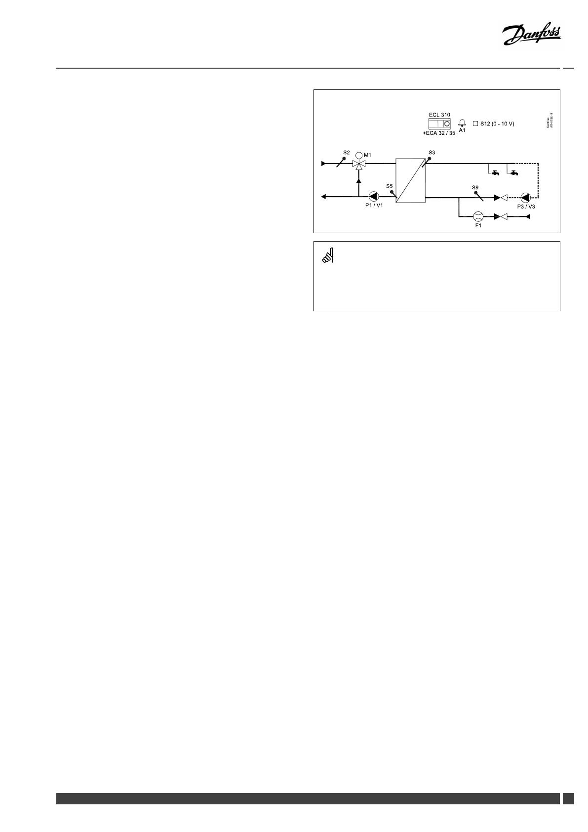
P318.10,ex.a,DHWapplicationwithcontrolvalve:
Theshowndiagramisafundamentalandsimpliedexampleanddoes
notcontainallcomponentsthatarenecessaryinasystem.
AllnamedcomponentsareconnectedtotheECLComfortcontroller.
Listofcomponents:
ECL310
ECLComfort310controller
ECA32
Built-inextensionmodule,0-10Voutputs
ECA35
Built-inextensionmodule,0-10Voutputsand
PWMoutputs
S2
Supplytemperaturesensor
S3
(mandatory)DHWowtemperaturesensor
S5
Returntemperaturesensor
S9
(mandatory)DHWcirculationreturntemperature
sensor
S12
0-10VinputfordesiredtemperatureatS3
F1
ColdWatermeter(pulsesignal)
P3
Speedcontrolofchargingpump(0-10VorPWM)
P3
DHWcirculationpump(ON-OFFcontrolled)
V3
Speedcontrolofcirculationpump(0-10Vor
PWM)
M1
Motorizedcontrolvalve(3-pointcontrolled)
A1
Alarm
DanfossDistrictEnergy
VI.JM.Q3.02
DEN-SMT/DK13

OperatingGuideECLComfort310,applicationP318
P318.10,ex.b,DHWapplicationwithcontrolpump:
Theshowndiagramisafundamentalandsimpliedexampleanddoes
notcontainallcomponentsthatarenecessaryinasystem.
AllnamedcomponentsareconnectedtotheECLComfortcontroller.
Listofcomponents:
ECL310
ECLComfort310controller
ECA32
Built-inextensionmodule,0-10Voutputs
ECA35
Built-inextensionmodule,0-10Voutputsand
PWMoutputs
S2
Supplytemperaturesensor
S3
(mandatory)DHWowtemperaturesensor
S5
Returntemperaturesensor
S9
(mandatory)DHWcirculationreturntemperature
sensor
S12
0-10VinputfordesiredtemperatureatS3
F1
ColdWatermeter(pulsesignal)
P1
Controlpump(ON-OFFcontrolled)
V1
Speedcontrolofcontrolpump(0-10VorPWM)
P3
DHWcirculationpump(ON-OFFcontrolled)
V3
Speedcontrolofcirculationpump(0-10Vor
PWM)
A1
Alarm
14DEN-SMT/DK
VI.JM.Q3.02
DanfossDistrictEnergy
OperatingGuideECLComfort310,applicationP318
P318.10,ex.c,DHWapplicationwithcontrolvalveandcontrolpump:
Theshowndiagramisafundamentalandsimpliedexampleanddoes
notcontainallcomponentsthatarenecessaryinasystem.
AllnamedcomponentsareconnectedtotheECLComfortcontroller.
Listofcomponents:
ECL310
ECLComfort310controller
ECA32
Built-inextensionmodule,0-10Voutputs
ECA35
Built-inextensionmodule,0-10Voutputsand
PWMoutputs
S2
Supplytemperaturesensor
S3
(mandatory)DHWowtemperaturesensor
S5
Returntemperaturesensor
S9
(mandatory)DHWcirculationreturntemperature
sensor
S12
0-10VinputfordesiredtemperatureatS3
F1
ColdWatermeter(pulsesignal)
P1
Controlpump(ON-OFFcontrolled)
V1
Speedcontrolofcontrolpump(0-10VorPWM)
P3
DHWcirculationpump(ON-OFFcontrolled)
V3
Speedcontrolofcirculationpump(0-10Vor
PWM)
M1
Motorizedcontrolvalve(3-pointcontrolled)
A1
Alarm
DanfossDistrictEnergy
VI.JM.Q3.02
DEN-SMT/DK
15

OperatingGuideECLComfort310,applicationP318
P318,ingeneral
UptotwoRemoteControlUnits,ECA30/31,canbeconnectedto
oneECLcontrollerinordertocontroltheECLcontrollerremotely.
AdditionalECLComfortcontrollerscanbeconnectedviatheECL
485businordertoutilizecommonoutdoortemperaturesignal,
timeanddatesignals.TheECLControllersintheECL485bus
systemcanworkasmasterandslaves.TheapplicationP318can
workaloneorasaslave.
Heat-meters:
Upto5heat-meterscanbeconnectedtotheM-busterminals.
DatacanbetransferredtotheSCADAsystemviaModbusandTCP/
IPtotheECLPortal.
TheP318applicationhaseventindicationsfor
•Chargingtemperature(P318.1)
•Tank(buffer)temperature(P318.1)
•DHWowtemperature(P310.10)
•Supplytemperature
•Anti-bacteria
Typically,aneventisregisteredifasettemperatureconditionis
notaccepted.Theeventscanbeprioritizedtobeindicatedas
informationoranalarm.
ThealarmA1(=relay6)canbeactivatedif:
•aneventoccurs
•atemperaturesensororitsconnectiondisconnects/short
circuits.(See:Commoncontrollersettings>System>Raw
inputoverview).
16DEN-SMT/DK
VI.JM.Q3.02
DanfossDistrictEnergy
OperatingGuideECLComfort310,applicationP318
PWM(PulseWidthModulation)
A200HzfrequencyisappliedtothePWMcontrolledpump.The
dutycycle(thepercentageoftheperiodtime)determinesthe
pumpspeed.
Pumpspeed,PWMor0–10Voltcontrolled
Sometypesofspeedcontrolledpumpsarelimitedtoaminimum
speed,forexample30%(PWMor3.0Volt).Eveniftheapplied
control%getslowerthan30%,thepumpspeedremainsonthe
minimumlevel*.
Furthermore,whentheappliedcontrol%getsbelow,forexample,
10%,thepumpswitchesOFF.Inordertogetthepumpswitched
ONagain,theappliedcontrol%mustexceed20%.
Thisbehaviorcan,atlowloadoratoobigpump,causeunstable
temperatureregulation.Toavoidthis,theP318hasafunction
wheretheappliedcontrolsignalisconvertedintoapulsedsignal.
Thepumpisshortlystoppedandthenstartedagain.Theresultisa
pumpspeedcontrolalsobelowtheminimumspeedlevel.
Theparameters"PWMperiod"(ID11565)and"Adapttime"(ID
11065)areusedforthisfunctionality.
*)Seethepumpmanufacturer'sdatasheet
Inputconguration
Inputs(asfromS7andup)whicharenotpartoftheapplicationcan
beconguredtobePt1000,0-10Volt,frequency(pulsecounter)
orDigitalinput.Thisfeaturemakesitpossibletocommunicate
extrasignals,suchastemperatures,pressures,ON/OFFconditions,
viaModbusandECLPortal.
ThecongurationisdonebymeansoftheECLTool(freesoftware
fordownload)ordirectlyinadedicatedmenuintheECLPortalor
theconnectionforModbus(BMS/SCADA).
Commissioning
WhentheP318hasbeenuploadedtheECLComfort310controller
startsinManualmode.Thiscanbeusedtoverifythecontrolled
componentsforcorrectfunctionality.
Dependingonsystemtype,itisrecommendedtochangesome
factorysettingsindividuallyinordertooptimizethefunctionality.
Thesesettingchanges,ifrequired,arelistedbelowthesystem
typesinthesection'Identifyingthesystemtype'.
Theapplicationkeymustbeinsertedinordertochangesettings.
Thecontrollerispre-programmedwithfactorysettingsthatareshown
inthe‘ParameterIDoverview’appendix.
DanfossDistrictEnergy
VI.JM.Q3.02
DEN-SMT/DK17
OperatingGuideECLComfort310,applicationP318
2.2Identifyingthesystemtype
Sketchyourapplication
TheECLComfortcontrollerseriesisdesignedforawiderange
ofheating,domestichot-water(DHW)andcoolingsystemswith
differentcongurationsandcapacities.Ifyoursystemdiffers
fromthediagramsshownhere,youmaywanttomakeasketch
ofthesystemabouttobeinstalled.Thismakesiteasiertouse
theOperatingGuide,whichwillguideyoustep-by-stepfrom
installationtonaladjustmentsbeforetheend-usertakesover.
TheECLComfortcontrollerisauniversalcontrollerthatcanbe
usedforvarioussystems.Basedontheshownstandardsystems,
itispossibletocongureadditionalsystems.Inthischapteryou
ndthemostfrequentlyusedsystems.Ifyoursystemisnotquite
asshownbelow,ndthediagramwhichhasthebestresemblance
withyoursystemandmakeyourowncombinations.
SeetheInstallationGuide(deliveredwiththeapplicationkey)for
applicationtypes/sub-types.
Adviceforsettings:
Factorysettingsinthesubtypearerelatedtoexamplea.
Someoftheapplicationexamplesneedchangeofdedicated
settings.
Seethedocumentationfortheapplication,deliveredwiththe
applicationkey.
P318.1,ex.a,cande
InternalDHWcirculation(DHWcirculationreturnpipeisconnected
totheDHWtank)
Issue:
Navigation:
IDno.:
Recommended
setting:
DHWcircuit(1):
InternalDHWcirculation
MENU\Settings\Application:'Cont.Tcontrol'
11054
OFF
P318.1,ex.b,dandf
ExternalDHWcirculation(DHWcirculationreturnpipeisconnected
totheheat-exchanger)
Issue:
Navigation:
IDno.:
Recommended
setting:
DHWcircuit(1):
ExternalDHWcirculation
MENU\Settings\Application:'Cont.Tcontrol'
11054
ON
Controlvalve(M1)orcontrolpump(P1/V1):
Nospecicsettingrelatedtocontrolitem.
18DEN-SMT/DK
VI.JM.Q3.02
DanfossDistrictEnergy

OperatingGuideECLComfort310,applicationP318
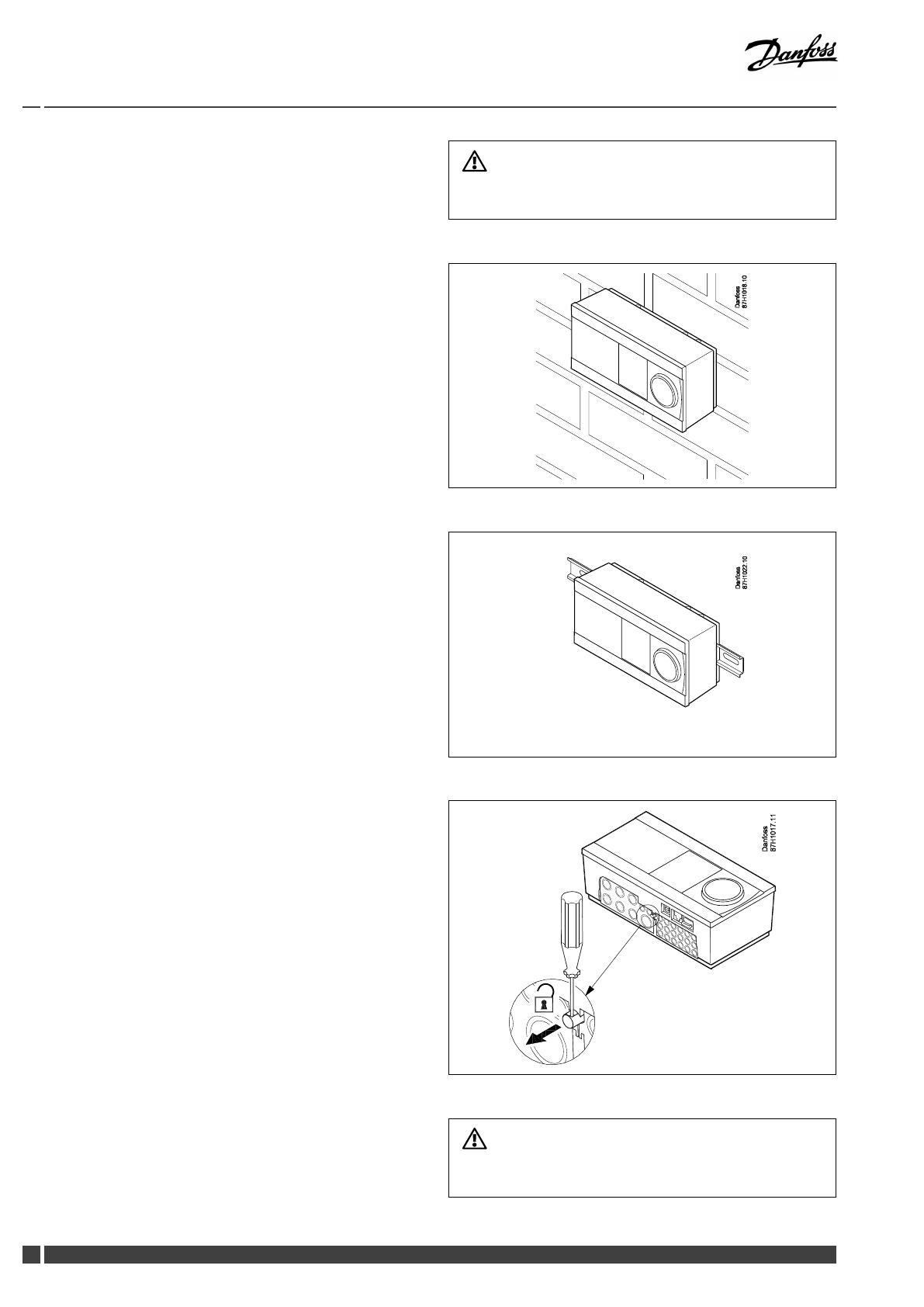
2.3Mounting
2.3.1MountingtheECLComfortcontroller
SeetheInstallationGuidewhichisdeliveredtogetherwiththe
ECLComfortcontroller.
Foreasyaccess,youshouldmounttheECLComfortcontrollernear
thesystem.
ECLComfort210/296/310canbemounted
•onawall
•onaDINrail(35mm)
ECLComfort296canbemounted
•inapanelcut-out
ECLComfort210canbemountedinanECLComfort310basepart
(forfutureupgrade).
Screws,PGcableglandsandrawlplugsarenotsupplied.
LockingtheECLComfort210/310controller
InordertofastentheECLComfortcontrollertoitsbasepart,secure
thecontrollerwiththelockingpin.
Topreventinjuriestopersonsorthecontroller,thecontrollerhasto
besecurelylockedintothebase.Forthispurpose,pressthelocking
pinintothebaseuntilaclickisheardandthecontrollernolonger
canberemovedfromthebase.
Ifthecontrollerisnotsecurelylockedintothebasepart,thereisarisk
thatthecontrollerduringoperationcanunlockfromthebaseandthe
basewithterminals(andalsothe230Va.c.connections)areexposed.
Topreventinjuriestopersons,alwaysmakesurethatthecontroller
issecurelylockedintoitsbase.Ifthisisnotthecase,thecontroller
shouldnotbeoperated!
DanfossDistrictEnergy
VI.JM.Q3.02
DEN-SMT/DK19
OperatingGuideECLComfort310,applicationP318
Theeasywaytolockthecontrollertoitsbaseorunlockitistousea
screwdriveraslever.
Mountingonawall
Mountthebasepartonawallwithasmoothsurface.Establishthe
electricalconnectionsandpositionthecontrollerinthebasepart.
Securethecontrollerwiththelockingpin.
MountingonaDINrail(35mm)
MountthebasepartonaDINrail.Establishtheelectrical
connectionsandpositionthecontrollerinthebasepart.Secure
thecontrollerwiththelockingpin.
DismountingtheECLComfortcontroller
Inordertoremovethecontrollerfromthebasepart,pulloutthe
lockingpinbymeansofascrewdriver.Thecontrollercannowbe
removedfromthebasepart.
Theeasywaytolockthecontrollertoitsbaseorunlockitistousea
screwdriveraslever.
20DEN-SMT/DK
VI.JM.Q3.02
DanfossDistrictEnergy
/