Page is loading ...

Page 1 of 8
The CMA-38 is a field-installable low ambient fan
speed control for 460V motors. The CMA-38 460V
head pressure control helps maintain the correct
condensing temperature/pressure, which results in a
constant head pressure. By adjusting the condenser
fan speed, the CMA-38 controls the airflow through
the condenser. A single desired temperature/pressure
setpoint adjustment will result in precise condensing
temperatures and stable head pressures.
The CMA-38 kit is for use with Bard models W24AB-C
wall-mount air conditioners.
The
CMA-38
kit consists of:
• 7960-847 Installation Instructions
• 902-2069 Fan Speed Control Box
• 910-2058 Outdoor Temperature Switch Assembly
• 8408-048 Freeze Protect Thermostat
• 5810-006 Flare Tee
• 1012-066 3/4" Screw (1)
• 8607-017 Terminal Block
• 1012-085 1/2" Self-Tapping Screws (5)
• 7950-004 Nylon Wire Ties (6)
• 7961-312-0338 CMA-38 Unit I.D. Label
Field-supplied tools needed:
• Personal protection equipment, including gloves
and safety glasses
• 5/16" nut driver
• 1/2" wrench (service port), 11/16" wrench (LAC
control) and 3/4" wrench (LAC assembly)
• Side cut pliers (for cable tie removal)
• Flat head screwdriver
• Small flat head screwdriver for securing wire in
terminal blocks
Bard Manufacturing Company, Inc.
Bryan, Ohio 43506
www.bardhvac.com
Manual: 7960-847B
Supersedes: 7960-847A
Date: 12-9-19
CMA-38 Low Ambient 460V Fan Speed Control
SUPPLEMENTAL INSTRUCTIONS
Sharp metallic edges.
Take care and wear appropriate protective
devices to avoid accidental contact with
sharp edges.
Failure to do so can result in personal
injury.
!
CAUTION
Exposed moving parts.
Disconnect all electrical power before
servicing.
Failure to do so can result in severe injury
or amputation.
!
WARNING
Electrical shock hazard.
Disconnect the remote electric power
supply or supplies before servicing.
Failure to do so can result in serious injury
or death.
!
WARNING

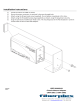
FIGURE 1
MIS-4078
CONTROL
BOX
4'' 12.5"
Manual 7960-847B
Page 2 of 8
Installation
1. Disconnect all power to the unit. Remove control
panel inner and outer covers, upper front panel and
both right-side and left-side condenser inlet grilles.
2. Mount the fan speed control box as shown in
Figure 1 using the three self-tapping screws.
The dimensions for mounting the control box are
provided in Figure 1.
3. Remove service cap and attach the pressure
transducer and flare tee to the liquid line as shown
in Figure 2; re-install the service cap on the end of
the service tee. Check for leaks.
4.
Attach the plug from the fan speed control box to the
pressure switch as shown in Figure 2.
5. Install outdoor temperature switch assembly to the
fan shroud and route wires through the bushing
and up to the control panel as shown in Figure 3
on page 4. This switch defeats Balanced Climate
airflow when the temperature falls below 50°F to
help prevent evaporator freeze up. Refer to the
unit installation manual for more information on
Balanced Climate operation.
6. Install freeze protect thermostat to the evaporator
coil as shown in Figure 4 on page 5. Route the
wires down through the copper bushing and into the
control panel with the blower motor wires.
7. Run all wires from the low ambient control
(LAC) box (except the ones going to the pressure
transducer) up through the bushing in the bottom
of the unit control box as shown in Figure 5 on

Manual 7960-847B
Page 3 of 8
FIGURE 2
MIS-3880
REINSTALL CAP
REMOVE CAP AND INSTALL
PRESSURE TRANSDUCER
TEE TO SERVICE PORT.
BOX
PLUG WITH
WIRES TO CONTROL
LIQUID LINE
RE-INSTALL CAP
page 6. Disconnect the black fan wire running
from the T2 terminal of the compressor contactor.
Install terminal block (as shown in Figure 5) and
reconnect the black fan wire to one side of the
terminal block. Run the black/red wire from LAC
to the terminal block so that it is connected to the
fan motor wire. Run the black wire from LAC to the
T2 terminal of the compressor contactor. Run the
black/white wire from LAC to the C terminal on the
24V transformer. Run the red/white wire from LAC
to the R (hot) terminal on the transformer. Run
the yellow wire from LAC to the T3 terminal of the
compressor contactor.
8.
Secure wires running on the outdoor section of the
unit using the supplied nylon wire ties as shown
in Figure 1). Be sure that there is no way that the
wires can come in contact with the fan blades or
any sharp edges.
9. Check wiring and control knob settings. See Figure
5 (page 6) and Figure 6 (page 7) for wiring and
suggested setpoints.
10. Find the purple wire not connected to anything that
is tucked in the cable duct (see Figure 5). Pull it
out and connect it to the LAC terminal block on
the terminal that is separate from the LAC control
wires. Connect the end of the outdoor temperature
switch that has the insulated quick connect to the
terminal block beside the purple wire. Connect the
other end of the outdoor temperature switch to the
Y terminal on the phase monitor. (Refer to Figure 7
on page 8 or the unit wiring diagram).
11. Connect the freeze protect thermostat wires in line
with the “Y” input signal to the compressor control
module (CCM). Refer to the unit wiring diagram.
For 1-phase units, connect the end with the 1/4”
quick connect to Y terminal on the CCM, and the
other end with the 1/4” tab to the yellow/white wire
coming from the low voltage terminal strip.
For 3-phase units, connect the wire end with
the 1/4” quick connect to “Y out” on the phase
monitor, and the other end with the 1/4” tab to the
yellow/black wire going to the CCM.
12. Apply “This unit is equipped with CMA-38 control
module” label to the inside of the inner control
panel cover above the wiring diagrams.
11/16" WRENCH
3/4" WRENCH
1/2" WRENCH

FIGURE 3
RUN WIRES THROUGH THE BUSHING
UP TO THE CONTROL PANEL
SCREW
PART #1012-085
OUTDOOR TEMP
SWITCH
PART #910-2058
MIS-4053
Manual 7960-847B
Page 4 of 8
13. Replace all panels, grilles and covers. This
completes the installation.
14. Check proper operation of the unit by energizing
the compressor in cooling mode. The condenser fan
motor should start and ramp up speed as system
pressure increases.
Sequence of Operation
Upon initiation, the CMA-38 will apply full voltage to
the fan motor for the time period selected with the Hard
Start knob (see Figure 6). Hard start time is adjustable
from 0.1 to 5 seconds. The hard start ensures correct
rotation of the condenser fan, even in windy conditions.
After a hard start, the control reads the temperature/
pressure sensor and the fan speed is adjusted until the
input temperature/pressure matches the setpoint.
The CMA-38 enables the user to set and adjust the
pressure to be maintained by the control. The setpoint
pressure is adjustable from 35-465 psig.

FIGURE 4
MIS-4054
USE ONE OF THE MIDDLE
HEADER STUBS TO ATTACH
THE FREEZE STAT TO THE
EVAPORATOR COIL
FREEZE STAT WIRES
RUN DOWN COPPER
THROUGH THE GROMMET
AND INTO THE CONTROL
PANEL WITH THE BLOWER
MOTOR WIRES
Manual 7960-847B
Page 5 of 8

FIGURE 5
MIS-4074
MOTOR
FROM FAN
MODULATING
LOW AMBIENT BOX
MIS-4074
TRANSFORMER
COMPRESSOR
CONTACTOR
TERMINAL BLOCK
CABLE DUCT
Manual 7960-847B
Page 6 of 8

FIGURE 6
MIS-3881 A
Black/Red
Yellow
Black
top 2 pins
(N.O. Setting)
position
Set to "MIN"
position
Set to "MIN"
position
Set to "315"
RED
BLACK
BLACK/WHITE
BLUE
Set jumper to
TO PRESSURE
TRANSDUCER
RED/WHITE
Manual 7960-847B
Page 7 of 8

FIGURE 7
Manual 7960-847B
Page 8 of 8
LPC
C
ALR
CC
Y
R
HPC
2
MINUTES
L2
T2
T1
L1
1012 1345678911
Phase Monitor
L2 L3
L1
Y
Yout
C
MIS-4052 B
PHASE
Black
Fan Motor
Purple W24 Units
Switch
Temp
(Behind LowVoltage Block)
12 Pin Plug
Blue on
UNITS
3 PHASE
Low Ambient
W24 Units
MONITOR
Outdoor
Contactor
Compressor
Terminal
Block #2
Control
Module
Compressor
Brown onBlack
Black
Yellow
Yellow
UNITS
Control
Outdoor
1 PHASE
NOTE:
CONNECT YELLOW WIRE FROM
OUTDOOR TEMP SENSOR TO
"Y" TERMINAL ON THE COMPRESSOR
CONTROL MODULE FOR 1-PHASE UNITS,
OR THE "Y" TERMINAL ON THE PHASE
MONITOR FOR 3 PHASE UNITS.
/