Page is loading ...

Page 1 of 6
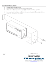
The purpose of the CMA-44 kit is to allow the
addition of sensors for connection to a DDC control
system. These sensors include a dirty filter switch, a
discharge air sensor, an airflow verification switch and a
compressor current sensor.
The CMA-44 kit is for use with Bard models W42-72AC
wall-mount air conditioners.
The CMA-44 consists of field-installable sensors for use
with DDC control systems. The CMA-44 includes:
• 7960-855 CMA-44 Supplemental Instructions
• 910-2070 Airflow Switch Assembly
• 910-2071 Filter Switch Assembly
• 910-2073 Filter Switch Light Assembly
• 910-2090 Compressor Current Sensor
• 910-1224 Discharge Air Sensor
• 8607-021 Low Voltage Terminal Board
• 7961-837 Terminal Board Label
• 7960-854 CMC-33 Supplemental Instructions
• 8201-159 Relay, DPDT
Bard Manufacturing Company, Inc.
Bryan, Ohio 43506
www.bardhvac.com
Manual: 7960-855
Supersedes: NEW
Date: 9-24-19
SUPPLEMENTAL INSTRUCTIONS
Exposed moving parts.
Disconnect all electrical power before
servicing.
Failure to do so can result in severe injury
or amputation.
!
WARNING
Electrical shock hazard.
Disconnect the remote electric power
supply or supplies before servicing.
Failure to do so can result in serious injury
or death.
!
WARNING
• 3018-2134 Orange Wire (2)
• 7950-005 Nylon Cable Clamp (2)
• 8611-028 1/2" Snap Bushing (2)
• 8611-047 3/4" Snap Bushing (2)
• 1012-065 Phillips Head Screw (7)
• 1012-086 Hex Head Screw (7)
• 1012-153 Smooth Hex Head Screw (2)
• 7950-012 Push Mount Cable Tie (6)
• 7950-004 Ladder Cable Tie (2)
• 7961-312-0512 CMA-44 Unit I.D. Label
Field-supplied tools needed:
• Personal protection equipment, including gloves
and safety glasses
• 5/16" nut driver
• Phillips head screwdriver
• Small flat head screwdriver for securing wire in
terminal blocks
• Multimeter for troubleshooting
CMA-44 DDC Sensors

Manual 7960-855
Page 2 of 6
INSTALLATION
1. Disconnect all power to wall mount before
installing sensors.
2. Remove inner and outer control panel covers.
Remove electric heater access panel, front
condenser grill and upper front door.
3. Install the airflow switch assembly (see Figure 1).
Use two (2) 1012-086 screws to attach the switch
bracket to the blower partition.
4. Install one (1) 8611-028 snap bushing in the back
of the blower partition and route the hose from the
airflow switch through the bushing as shown in
Figure 1.
5. Secure the hose to the blower partition using the
7950-005 nylon clamp and the 1012-153 smooth
hex head screw as shown in Figure 1.
6. Install the 8611-047 snap bushings in the filter
partition and control panel bracket as shown in
Figure 1.
7. Route the wires from the airflow switch down
through the blower partition and into the control
panel as shown in Figure 1.
8. Install the filter switch items using the 7960-854
instructions. Filter switch testing and adjustment
can be made after all sensors have been installed.
Figure 1
Sharp metallic edges.
Take care and wear appropriate protective
devices to avoid accidental contact with
sharp edges.
Failure to do so can result in personal
injury.
!
CAUTION
MIS-4092
AIRFLOW SWITCH ASSEMBLY
PART #910-2070
RUN HOSE DOWN THE BLOWER PARTITION
USING BUSHING PART #8611-028 THEN
SECURE THE HOSE USING CLAMP
PART #7950-005 AND SCREW PART #1012-153
FEED WIRES
THRU 3/4" SNAP
BUSHING 8611-047

Manual 7960-855
Page 3 of 6
9. Remove screw from the electric heater bracket (see
Figure 2).
10. Install the discharge air sensor.
11. Route the discharge air sensor wires down through
the conduit elbow, into the upper control panel and
then down into the main control panel. See Figure
3 on page 4 for routing.
12. Remove the black wire from the compressor
contactor (see Figure 4 on page 5).
13. Route the wire through the hole in the current
sensor and reconnect wire.
14. Mount the current sensor to the panel directly
below the control panel as shown in Figure 4.
15. Route the current sensor wire into the control panel
(see Figure 4).
16. Attach wires to the terminal board according to the
wiring diagram (see Figure 5 on page 6).
17. Carefully push wires into the low voltage box and
install terminal board (see Figure 4).
18. Attach terminal board label to terminal board (see
Figure 4).
19. Attach “CMA-44” label and wiring diagram to the
inner control panel cover beside the unit wiring
diagrams.
20. Make low voltage connections from the DDC
controller to the terminal board.
21. Install the blower access cover, front grill, inner
control panel cover and heater access panel.
22. Apply power to unit
23. Refer to filter switch manual 7960-854 to test and
adjust the filter switch setting.
24. Install the outer control panel cover. This
completes the installation.
Figure 2
MIS-1141
REMOVE SCREW
ROUTE WIRES TO
CONTROL PANEL
INSTALL DISCHARGE
SENSOR ASSEMBLY
AND INSTALL SCREWS

Manual 7960-855
Page 4 of 6
Figure 3
UPPER CONTROL PANEL
MIS-4089
THE MAIN CONTROL PANEL.
ROUTE THE DISCHARGE AIR
SENSOR WIRES FROM THE
UPPER CONTROL PANEL TO
MAIN CONTROL PANEL
THE UPPER CONTROL PANEL.
RIGHT SIDE VIEW
ROUTE THE DISCHARGE AIR
SENSOR WIRES DOWN THROUGH
THE CONDUIT ELBOW AND INTO
DISCHARGE AIR SENSOR

Manual 7960-855
Page 5 of 6
Figure 4
MIS-4093
PART #910-2090
ROUTE WIRES THROUGH BUSHING
CURRENT SENSOR ASSEMBLY
HOLE IN CURRENT SENSOR
WIRE IS TO BE ROUTED THROUGH
NOTE: COMPRESSOR'S BLACK
TWO WIRES FROM CURRENT
TRANSDUCER CONNECT TO
BACK OF TERMINAL STRIP
PART #8607-021
PART #1012-065
(2) SCREWS
PART #7961-837
LABEL
TERMINAL STRIP
PART #8607-021

Manual 7960-855
Page 6 of 6
LOW VOLTAGE SENSOR CONNECTIONS
MIS-4090
MAX
Tan COM .15A
COMPRESSOR CURRENT SENSOR
Blue/White
Orange/Black
AIRFLOW SWITCH
9
Orange/Black
24 VAC
White
White
FILTER SWITCH RELAY
Blue/White
@24 VAC
125 VA
12
11
15
13
14
TO THE LOW VOLTAGE TERMINAL BLOCK
125VA @
10k ohm
30 VAC
@ 77°F
10
Pink +
DISCHARGE AIR SENSOR
NOTE: USE CLASS ONE WIRING FOR CONNECTION
16
Figure 5
/