Page is loading ...

MP250i WELDER
INS TRUCTIONS
Item #21180

2 Eastwood Technical Assistance: 800.544.5118 >> techelp@eastwood.com
The EASTWOOD MP250i WELDER provides the ability to MIG, TIG or ARC (Stick) weld all from a single, high-powered, self-contained unit. Inverter Technology
provides the capability of welding thin or heavy gauge steel with precision and ease. For additional versatility and aluminum welding capability, add the optionally
available Eastwood # 20172 Spool Gun.
READ AND UNDERSTAND ALL INSTRUCTIONS AND PRECAUTIONS BEFORE PROCEEDING.
This unit emits a powerful high voltage and extreme heat which can cause severe burns, dismemberment, electrical shock and death. Eastwood shall not be held
liable for consequences due to deliberate or unintentional misuse of this product.
(1) MP250i Welder
(1) Front Caster Assembly
(1) Rear Wheel/Gas Cylinder Tray Assembly
(2) Gas Cylinder Brackets
(2) Gas Cylinder Chains
(18) M5 x 12mm Screws
(3) M5 Nuts
(6) M5 Flat Washers
(3) M5 Lockwashers
(1) Shielding Gas Hose, 4.6’ [1.4m]
(1) Ground Clamp with 14.8’ [4.5m] Cable
(1) MIG Torch with 14.8’ [4.5m] Cable,
0.030” Tip Installed
(2) Spare Contact Tips (0.030” & 0.035”)
(1) Contact Tip Wrench
(1) 2mm Hex Key
(1) Electrode Holder with 14.8’ [4.5m] Cable
(1) TIG Torch (Tweco Style) with 14.8’
[4.5m] cable and 17.8’ [5.5m] Gas Line
(1) #5 Gas Nozzle (5/16”) (Installed)
(1) #6 Gas Nozzle (3/8”)
(1) #7 Gas Nozzle (7/16”)
(1) Short Back Cap (Installed)
(1) Long Back Cap
(1) Collet Body, 3/32” [2.4mm] (Installed)
(1) Collet, 1/16” [1.6mm]
(1) Collet, 1/8” [3.2mm]
(1) 1/16” x 6” [2.0mm x 150mm]
Tungsten (Red)
(1) Adapter Cord, 24” [0.6m]
(1) Welding Mask
(1) Hammer/Brush
(1) Instruction Manual
STATEMENT OF LIMITED WARRANTY
The Eastwood Company (hereinafter “Eastwood”) warrants to the end user (purchaser) of all new welding and cutting equipment (collectively called the “products”) that it will
be free of defects in workmanship and material. This warranty is void if the equipment has been subjected to improper installation, improper care or abnormal operations.
WARRANTY PERIOD:
All warranty periods begin on the date of purchase from Eastwood. Warranty Periods are listed below, along with the products covered during those warranty periods:
3 Year Warranty on Material, Workmanship, and Defects:
• Eastwood MP250i Welder Items not covered under this warranty: Consumables, Collets, Collet Bodies, Electrodes, Nozzles, Ground Clamp and Cable.
All other components are covered by the warranty and will be repaired or replaced at the discretion of Eastwood.
2 Years:
• All Welding Helmets.
CONDITIONS OF WARRANTY TO OBTAIN WARRANTY COVERAGE:
Purchaser must first contact Eastwood at 1-800-345-1178 for an RMA# before Eastwood will accept any Welder returns.
Final determination of warranty on welding and cutting equipment will be made by Eastwood.
WARRANTY REPAIR:
If Eastwood confirms the existence of a defect covered under this warranty plan, Eastwood will determine whether repair or replacement is the most suitable option to rectify
the defect. At Eastwood’s request, the purchaser must return, to Eastwood, any products claimed defective under Eastwood’s warranty.
FREIGHT COSTS:
The purchaser is responsible for shipment to and from Eastwood.
WARRANTY LIMITATIONS:
EASTWOOD WILL NOT ACCEPT RESPONSIBILITY OR LIABILITY FOR REPAIRS UNLESS MADE BY EASTWOOD. EASTWOOD’S LIABILITY UNDER THIS WARRANTY SHALL
NOT EXCEED THE COST OF CORRECTING THE DEFECT OF THE EASTWOOD PRODUCT. EASTWOOD WILL NOT BE LIABLE FOR INCIDENTAL OR CONSEQUENTIAL DAMAGES
(SUCH AS LOSS OF BUSINESS, ETC.) CAUSED BY THE DEFECT OR THE TIME INVOLVED TO CORRECT THE DEFECT. THIS WRITTEN WARRANTY IS THE ONLY EXPRESS
WARRANTY PROVIDED BY EASTWOOD WITH RESPECT TO ITS PRODUCTS. WARRANTIES IMPLIED BY LAW SUCH AS THE WARRANTY OF MERCHANTABILITY ARE
LIMITED TO THE DURATION OF THIS LIMITED WARRANTY FOR THE EQUIPMENT INVOLVED. THIS WARRANTY GIVES THE PURCHASER SPECIFIC LEGAL RIGHTS.
THE PURCHASER MAY ALSO HAVE OTHER RIGHTS WHICH VARY FROM STATE TO STATE.
CONTENTS

DUTY CYCLE
The rated Duty Cycle refers to the amount of welding that can be done within an amount of time. The Eastwood MP250i has a Duty Cycle of 60% at 250 Amps.
It is easiest to look at your welding time in blocks of 10 Minutes and the Duty Cycle being a percentage of that 10 Minutes. If welding at 250 Amps with a
60% Duty Cycle, within a 10 Minute block of time you can weld for 6 Minutes with 4 Minutes of cooling for the Welder.
If the Duty Cycle is exceeded, the Welder will automatically shut off, however the fan will continue running to cool the internal components. When a safe temperature
has been reached, the Welder will automatically switch the Welder output back on. To increase the Duty Cycle you can turn down the Voltage Output control.
To order parts and supplies: 800.345.1178 >> eastwood.com 3
SPECIFICATIONS
POWER SUPPLY
Solid Stainless Flux Core
Wire Type and Diameter
0.030-0.045”
[0.8-1.2mm]
0.030-0.045”
[0.8-1.2mm]
0.030-0.045”
[0.8-1.2mm]
MIG WELDING WIRE
4043 Aluminum
Wire Type and Diameter
0.030-0.035”
[0.8-0.9mm]
SPOOL GUN WELDING WIRE
Type
E6010 E6011 E6013 E7014 E7018
Diameter
1/16”, 3/32”,
1/8”, 7/32”
1/16”, 3/32”,
1/8”, 7/32”
1/16”, 3/32”,
1/8”, 7/32”
1/16”, 3/32”,
1/8”, 7/32”
1/16”, 3/32”,
1/8”, 7/32”
Polarity
DCEN DCEN DCEN, DCEP DCEN, DCEP DCEP
ARC WELDING RODS
Power Voltage (V)
1 phase 240V±10% 1 phase 120V±10%
Frequency (Hz)
50/60
No Load Voltage (V)
61
Rated Input Current (Amps)
MIG = 47.3
TIG = 35.7
Arc = 53.5
MIG = 42
TIG = 31.2
Arc = 51.1
Output Current Adjustment (Amps)
MIG = 50-250
TIG = 15-250
Arc = 25-250
MIG = 50-140
TIG = 15-140
Arc = 25-140
Output Voltage (V)
MIG = 16.5-26.5
TIG = 10.6-20
Arc = 21-30
MIG = 16.5-21
TIG = 10.6-15.6
Arc = 21-25.6
Duty Cycle (%)
60% @ 250 Amps
Power Factor
0.73
Efficiency (%)
80
Wire Feed Speed (ft/min)
78-629
Post Flow Time (seconds)
1.0 ± 0.5
Weight
96 lbs. [43.6kg]
Dimensions
36” x 21” x 31” [900mm x 765mm x 765mm]

4 Eastwood Technical Assistance: 800.544.5118 >> techelp@eastwood.com
DANGER indicates a hazardous situation which, if not avoided, will result in death or serious injury.
WARNING indicates a hazardous situation which, if not avoided, could result in death or serious injury.
CAUTION used with the safety alert symbol, indicates a hazardous situation which, if not avoided, could result in minor or moderate injury.
NOTICE is used to address practices not related to personal injury.
ELECTRIC SHOCK CAN CAUSE INJURY OR DEATH!
• Improper use of an electric Welder can cause electric shock, injury and death! Read all precautions described in the Welder Manual to
reduce the possibility of electric shock.
• Disconnect Welder from power supply before assembly, disassembly or maintenance of the torch, contact tip and when installing or
removing nozzles.
• Always wear dry, protective clothing and leather welding gloves and insulated footwear. Use suitable clothing made from durable
flame-resistant material to protect your skin.
• If other persons or pets are in the area of welding, use welding screens to protect bystanders from sparks and ARC rays.
• Always operate the Welder in a clean, dry, well ventilated area. Do not operate the Welder in humid, wet, rainy or poorly ventilated areas.
• The electrode and work (or ground) circuits are electrically “hot” when the Welder is on. Do not allow these “hot” parts to come in
contact with your bare skin or wet clothing.
• Separate yourself from the welding circuit by using insulating mats to prevent contact from the work surface.
• Be sure that the work piece is properly supported and grounded prior to beginning an electric welding operation.
• Always attach the Ground Clamp to the piece to be welded and as close to the weld area as possible. This will give the least resistance
and best weld.
WELDING SPARKS CAN CAUSE FIRE OR EXPLOSION!
• Electric welding produces sparks which can be discharged considerable distances at high velocity igniting flammable or exploding vapors
and materials.
DO NOT operate electric arc Welder in areas where flammable or explosive vapors are present.
DO NOT use near combustible surfaces. Remove all flammable items from the work area where welding sparks can reach (min. of 35 feet).
• Always keep a fire extinguisher nearby while welding.
• Use welding blankets to protect painted and or flammable surfaces; rubber weather-stripping, dash boards, engines, etc.
• Ensure power supply has properly rated wiring to handle power usage.
SAFETY INFORMATION
IMPORTANT NOTE:
These instructions are intended only to provide the user with some familiarity of the Eastwood MP250i. Electric Welding is a highly complex procedure with many
variables. If you have no prior experience with Electric Welding, it is extremely important to seek the advice of someone experienced in Electric Welding for instruc-
tion, enroll in a local technical school welding course or study a comprehensive how-to DVD and obtain a good quality reference book on Electric Welding as there
is a moderate learning curve necessary before achieving proficiency in Welding different metals such as steel, stainless steel and aluminum. It is also strongly
recommended that the user adhere to the American Welding Society guidelines, codes and applications prior to producing welds where safety is affected.
Welding can be dangerous to you and other persons in the work area. Read and understand this instruction manual before using your Eastwood welding machine.
Injury or death can occur if safe welding practices are not followed. Safety information is set forth below and throughout this manual. Save these instructions for
future reference.
To learn more about welding safety, read OSHA Title 29 CFR 1910, available at www.osha.gov; ANSI Z49.1, “Safety in Welding, Cutting and Allied Processes,”
available at www.aws.org; and the consumable manufacturer’s Safety Data Sheets.
The following explanations are displayed in this manual, on the labeling, and on all other information provided with this product:

To order parts and supplies: 800.345.1178 >> eastwood.com 5
ELECTROMAGNETIC FIELDS CAN BE A HEALTH HAZARD!
• The electromagnetic field that is generated during arc welding may interfere with various electrical and electronic devices such as
cardiac pacemakers. Anyone using such devices should consult with their physician prior to performing any electric welding operations.
• Exposure to electromagnetic fields while welding may have other health effects which are not known.
ARC RAYS CAN INJURE EYES AND BURN!
• Arc rays produce intense ultraviolet radiation which can burn exposed skin and cause eye damage. Use a shield with the proper filter
(a minimum of #11) to protect your eyes from sparks and the rays of the arc when welding or when observing open arc welding
(see ANSI Z49.1 and Z87.1 for safety standards).
• Use suitable clothing made from durable flame-resistant material to protect your skin.
• If other persons or pets are in the area of welding, use welding screens to protect bystanders from sparks and arc rays.
FUMES AND WELDING GASES CAN BE A HEALTH HAZARD!
• Fumes and gasses released during welding are hazardous. Do not breathe fumes that are produced by the welding operation.
• Prolonged inhalation of welding fumes above safety exposure limits can injure the lungs and other organs.
• Use enough ventilation and/or exhaust at the arc to keep fumes and gases from your breathing area.
• Use an OSHA approved respirator when welding in confined spaces or where there is inadequate ventilation.
• Never weld coated materials including, but not limited to: cadmium plated, galvanized, lead based paints.
BUILDUP OF GAS CAN INJURE OR KILL!
• Shut off gas supply when not in use.
• Ensure adequate ventilation
• Do not weld in confined areas.
• Always turn your face away from valve outlet when opening cylinder valve.
CYLINDERS CAN EXPLODE IF DAMAGED!
Shielding gas cylinders contain gas under high pressure. If damaged, a cylinder can explode. As gas cylinders are a normal component of the
welding process, use extra care to handle them carefully.
• Protect compressed gas cylinders from excessive heat, mechanical shocks, physical damage, slag, open flames, sparks and arcs.
Keep away from any welding or other electrical circuits.
• Install cylinders in an upright position by securing to a specifically designed rack, cart or stationary support to prevent falling or
tipping over.
• Never weld on a pressurized cylinder or explosion will occur.
• Use only correct shielding gas cylinders, regulators, hoses and fittings designed for the specific application; maintain them and all
related components in good condition.
• Keep protective cap in place over valve except when cylinder is in use.
• Use proper equipment, procedures and have adequate help when moving or lifting cylinders.
SAFETY INFORMATION

6 Eastwood Technical Assistance: 800.544.5118 >> techelp@eastwood.com
HOT METAL AND TOOLS WILL BURN!!
• Electric welding heats metal and tools to temperatures that will cause severe burns!
• Use protective, heat resistant gloves and clothing when using Eastwood or any other welding equipment. Never touch welded work
surface, torch tip or nozzle until they have completely cooled.
FLYING METAL CHIPS CAN CAUSE INJURY!
• Grinding and sanding will eject metal chips, dust, debris and sparks at high velocity. To prevent eye injury wear approved safety glasses.
• Wear an OSHA-approved respirator when grinding or sanding.
• Read all manuals included with specific grinders, sanders or other power tools used before and after the welding process. Be aware of
all power tool safety warnings.
FIRST AID
• If exposed to excessive fumes move to an area with fresh air. Follow safety information on manufacturer’s Safety Data Sheet.
• For other injuries follow basic first aid techniques and call a physician or emergency medical personnel.
SAFETY INFORMATION
CONNECTING THE WELDER TO A POWER SOURCE
The Eastwood MP250i Welder has dual current capability and requires a dedicated 120 VAC, 20 Amp or a 240 VAC, 50 Amp. 60HZ grounded outlet protected by a
circuit breaker. The plug installed on the Welder is a NEMA 6-50P and should be used with a NEMA 6-50R receptacle. If using an extension cord, use a minimum
6 AWG cord for up to 25 feet.

To order parts and supplies: 800.345.1178 >> eastwood.com 7
ASSEMBLY
FRONT WHEELS
• Pull Welder from packaging, lift front end and support it securely.
• Using three M5 Nuts and Washers, locate over studs and attach the
front Caster Assembly and Front Caster Spacer to the underside of
the cabinet (FIG 1).
REAR WHEELS
• Lift and support rear end of Welder.
• Using (4) M5 x 12mm screws on rear and three M5 x 20mm Screws and
Washers at the underside, attach the Rear Wheel/Tray Assembly to the
underside and rear of the cabinet (FIGS 2 & 3).
TANK SUPPORTS
• With flanges facing downward, attach the two Tank Supports to the rear
of the cabinet with three M5 x 12mm screws each (FIG 4).
TANK CHAINS
• Hook ends of Tank Chains into the slots on the outer corners of the
Tank Supports (FIG 4).
FIG. 1
FIG. 2
FIG. 3
FIG. 4

8 Eastwood Technical Assistance: 800.544.5118 >> techelp@eastwood.com
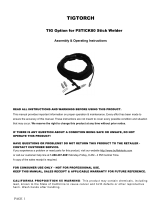
CONTROL AND DISPLAY PANEL
The Eastwood MP250i Front Panel
is arranged with 8 major groups
of Function Controls and
LED Indicators. They are as follows:
1. VRD Indicator
2. MIG/TIG/ARC Selector Button
3. MIG Torch/Spool Gun Selector Button
4. 2T/4T Selector Button
5. Inductance Adjustment Knob
6. Voltage Adjustment Knob
7. Current/Wire Speed Adjustment Knob
8. Overload Condition Indicator
1. VRD Switch: VRD = voltage reducing device. This function drops voltage when not welding to help prevent potential ARC start or shock when replacing
an electrode. Normal output is 60v, while VRD drops the no-load voltage to roughly 24v. To turn the function on or off, you must be in the Stick Welding
setting with Amperage setting at 108 amps, then press and hold the 2T/4T button. Illuminates GREEN when on.
2. MIG Torch/Spool Gun Switch: (MIG/TIG/ARC Switch Must be in MIG mode). Select for Wire Feed Torch or optional
Spool Gun (not included)
3. MIG/TIG/ARC (Stick) Switch: Used to select between MIG, TIG or ARC (Stick) welding functionality.
4. 2T / 4T 2T/4T SWITCH:
2T: For 2-step operation of short welding.
- Depress trigger and hold in. Pre-flow and Arc begin.
- To end arc, release trigger and Arc will terminate followed by the predetermined post flow.
4T: For 4-step operation of long welding.
- Depress trigger and hold in. Pre-flow and Arc begin.
- Once the Arc has started, release the trigger. The Arc will stay lit.
- To terminate the Arc, depress trigger once again and hold until Arc termination is desired and release the trigger.
- Releasing the trigger ta this point will terminate the Arc, followed by the predetermined post flow.
5. Inductance Setting Knob: The inductance setting controls the rate of current rise following the short-circuit state. That is during the time when the wire
is short circuiting into the weld puddle. This setting affects the arc time too. That is the amount of time the short circuit cycle spends arcing and providing
heat to the puddle A high inductance setting increases the time of each individual arc cycle and therefore can improve wetting of the puddle. This produces
a “softer” puddle which is excellent for smooth fillet welds. A low inductance increases the frequency of each short circuit/arc cycle and can be useful for
pinpointing a narrow bead in some joints. Offers greater penetration however it will produce more spatter.
6. Voltage Control Knob: Controls the voltage output range for MIG; 15 to 30 Volts. Voltage value is indicated by the digital LED display.
7. Wire Speed / Arc Control Knob: Dual Function Control and Display
Press “A” Button to select Arc Current. The Knob controls the Amperage output while the Digital LED displays the Amperage value.
Current Range; 15 to 250 AMPS.
Press “Inches/Min Button to select Wire Speed. The Knob controls the Wire Speed when MIG welding while the Digital LED displays the Wire Speed value.
Speed range; 78 n/min to 627 in/min.
8. Overload Indicator: Illuminates GREEN when Duty Cycle has been exceeded, the Welder is overloaded or if other abnormalities exist.
FIG. 4
1
2
4
5
6
7
3
8

To order parts and supplies: 800.345.1178 >> eastwood.com 9
SET UP AND OPERATION FOR MIG WELDING
SET UP FOR MIG WELDING
Installing the MIG Welding Gun
• Open the side door of the Welder and loosen the Welding Gun
Thumb Screw (FIG 7).
• Slide the brass body of the Welding Gun in through the front of the Welder
into the Welding Gun Power Connection located at the lower left front panel
(FIG 8). Be sure to insert until it bottoms against the drive assembly or a
gas leak may occur.
• Tighten the Welding Gun Torch Thumbscrew securely.
• Connect the male metal plug to the female Cannon Plug Connection on
the front of the Welder (FIG 8).
• Switch the “MIG/TIG/ARC” Selector Button located on the Front Panel
to the MIG Position and switch “MIG Torch/Spool Gun” Switch to
“MIG Torch” (FIG 5).
FIG. 7
FIG. 6
FIG. 8
Wire
Tensioners
✓
✓
MIG Gun
Thumbscrew
Drive Roller
Thumbscrews
Drive
Rollers
✓
✓
✓
✓
✓
MIG Gun Power
Connection
Cannon Plug
Connection
Polarity
Jumper Lead
“–” Polarity
Connection
“+” Polarity
Connection
✓
✓
✓
✓
✓

10 Eastwood Technical Assistance: 800.544.5118 >> techelp@eastwood.com
Installing the Ground Cable and Clamp for Solid Wire MIG with Shielding Gas
MIG (DCEP) (Illustration MIG DCEP)
• Locate the Ground Clamp with Cable and connect the plug on the cable end to
the ( – ) connector on the Front Panel of the Welder. To connect the plug, line
up the key on the plug with the keyway on the socket of the Welder, insert the
plug and twist Clockwise until it is tight (FIGS 6 & 8).
• Attach the MIG Torch connector to the MIG/TIG Torch connection on the Lower
Left Front Panel. To connect the plug, line up the key on the plug with the
keyway on the socket of the Welder, insert the plug and twist Clockwise until
it is tight (FIG 6).
• Install the Polarity Jumper Lead into the ( + ) connector by inserting the keyed
brass connector and rotating to lock in place (FIGS 6 & 8).
Changing the Polarity
To use a Flux Cored wire, the Polarity must be changed to the DCEN configuration:
Flux-cored MIG (DCEN) (Illustration FLUX DCEN)
• Remove the Ground Clamp Cable connection from the lower Front Panel
by rotating and pulling out.
• Install the Ground Clamp Cable connector by inserting the keyed brass
connector into the ( + ) connector and rotating to lock in place (FIGS 6 & 8).
Install the Polarity Jumper Lead into the ( - ) connector by inserting the
keyed brass connector and rotating to lock in place (FIGS 6 & 8).
INSTALLING THE SHIELDING GAS SUPPLY
• Shut off gas supply when not in use.
• Ensure adequate ventilation
• Do not weld in confined areas.
• Always turn your face away from valve outlet when opening cylinder valve.
• Protect compressed gas cylinders from excessive heat, mechanical shocks, physical damage, slag, open flames, sparks and arcs.
Keep away from any welding or other electrical circuits.
• Install cylinders in an upright position by securing to a specifically designed rack, cart or stationary support to prevent falling or tipping over.
• Never weld on a pressurized cylinder or explosion will occur.
• Use only correct shielding gas cylinders, regulators, hoses and fittings designed for the specific application; maintain them and all related
components in good condition.
• Keep protective cap in place over valve except when cylinder is in use.
• Use proper equipment, procedures and have adequate help when moving or lifting cylinders.
Illustration
FLUX DCEN
ELECTRIC SHOCK CAN CAUSE INJURY OR DEATH!
• Disconnect Welder from power supply before beginning.
BUILDUP OF GAS CAN INJURE OR KILL!
CYLINDERS CAN EXPLODE IF DAMAGED!
Shielding gas cylinders contain gas under high pressure.
If damaged, a cylinder can explode. As gas cylinders are
a normal component of the welding process, use extra
care to handle them carefully.
MIG( P)DCE
Illustration
MIG DCEP

To order parts and supplies: 800.345.1178 >> eastwood.com 11
A Shielding Gas Bottle is NOT INCLUDED with your Eastwood MP250i but is necessary to weld using
Solid Wire. It can be bought at most local Welding Supply Stores. Eastwood recommends the use of
75% Argon / 25% CO2 for shielding gas when MIG welding Steel, 100% Argon for Aluminum,
and Tri-Mix (90% He / 7.5% Ar / 2.5% CO2) for Stainless Steel.
1. Place your Shielding Gas Bottle on the Rear Tray of the MP250i and mount it securely with the
included Cylinder Retaining Chains so that the cylinder cannot fall over.
2. Remove the cap from the Shielding Gas Bottle.
3. Insert the large brass male fitting on the Shielding Gas Regulator (NOT INCLUDED, Eastwood
#12238 recommended) into the female fitting on the Shielding Gas Bottle.
4. Tighten the fitting with a wrench until snug, do not over tighten.
5. Connect either end of the Gas Line included with your Eastwood MP250i to the fitting on the
regulator and wrench tighten until snug.
6. Connect the other end of the gas line to the fitting on the rear of the Eastwood MP250i and wrench
tighten until snug (FIG 9).
7. Check the gas line for leaks by slowly opening the valve on the gas bottle. When welding the valve
on the bottle should always be all the way open.
DRIVE ROLLERS
The Eastwood MP250i is designed to use 0.030 to 0.045 wire and is equipped with two Dual-Groove
Drive Rollers. As assembled, it will accept 0.030”/0.035” [0.8mm/0.09mm] wire. To use 0.040”/0.045”
[1.0mm/1.2mm] wire, the Drive Rollers must be reversed.
To do so:
• Unthread two Thumbscrews.
• Pull Drive Rollers from shafts.
• The indicted wire sizes are stamped on the faces of the Drive Rollers.
• Choose the wire size needed and slip the Drive Rollers back onto the shafts with the desired wire size stamping facing inward (FIG 7).
• Replace Thumbscrews.
WIRE SPOOL
The Eastwood MP250i can be used with either an 8”or a 12”” wire spool.
To install an 8”or 12” Wire Spool
• Open the door of the Welder and remove the Spool Retaining Knob from
the Wire Spool Spindle.
• Slide the Wire Spool onto the center of the Spindle (FIG 10).
When doing so, be sure the Drive Pin of the Spindle is engaged
with a spoke of the Spool.
• Reinstall the Spool Retaining Knob.
• To set the spool tension, incrementally tighten the Spool Retaining Knob
until there is a slight resistance to spinning the wire spool on the spindle.
(FIG 10). If the tension is set too loose the wire spool will freely spin on
the shaft and unspool all of the wire. If the tension is too tight, the Drive
Roller will have difficulty pulling the wire off the spool and
some slipping may occur.
FIG. 9
Power Cord
✓
Breaker
Shielding Gas
Connection
✓
✓
FIG. 10
Quick Feed
Button
Wire Spool
Retaining Knob
Wire Inlet Tube
Tensioners
✓
✓
✓
✓
✓
Tension Arms
✓
✓

12 Eastwood Technical Assistance: 800.544.5118 >> techelp@eastwood.com
ELECTRIC SHOCK CAN CAUSE INJURY OR DEATH!
• Improper use of an electric Welder can cause electric shock, injury and death! Read all precautions described in the Welder
Manual to reduce the possibility of electric shock.
• Disconnect Welder from power supply before assembly, disassembly or maintenance of the torch, contact tip and when installing
or removing nozzles.
• Always wear dry, protective clothing and leather welding gloves and insulated footwear. Use suitable clothing made from durable
flame-resistant material to protect your skin.
• If other persons or pets are in the area of welding, use welding screens to protect bystanders from sparks.
• Always operate the Welder in a clean, dry, well ventilated area. Do not operate the Welder in humid, wet, rainy or poorly ventilated
areas.
• The electrode and work (or ground) circuits are electrically “hot” when the Welder is on. Do not allow these “hot” parts to come
in contact with your bare skin or wet clothing.
• Separate yourself from the welding circuit by using insulating mats to prevent contact from the work surface.
• Be sure that the work piece is properly supported and grounded prior to beginning an electric welding operation.
• Always attach the ground clamp to the piece to be welded and as close to the weld area as possible. This will give the least
resistance and best weld.
WELDING SPARKS CAN CAUSE FIRE OR EXPLOSION!
• Electric welding produces sparks which can be discharged considerable distances at high velocity igniting flammable or exploding
vapors and materials.
• Do not operate electric arc Welder in areas where flammable or explosive vapors are present.
• Do not use near combustible surfaces. Remove all flammable items within 35 feet of the welding area.
• Always keep a fire extinguisher nearby while welding.
• Use welding blankets to protect painted and or flammable surfaces; rubber weather-stripping, dash boards, engines, etc.
• Ensure power supply has properly rated wiring to handle power usage.
THREADING WIRE THROUGH THE DRIVE MOTOR TO THE WELDING GUN
This Welder uses wire sizes ranging from 0.030” to 0.045” (0.8mm to 1.2mm). To install the welding wire follow the procedure outlined below:
1. Turn the power switch on the Upper rear Panel to the off position and unplug the Welder from the power supply.
2. Remove the Contact Tip and Nozzle from the end of the MIG Torch.
3. Unlock the Pressure Adjusters and raise the Tension Arms (FIG 10).
4. Pull out a length of welding wire from the wire spool carefully. IMPORTANT NOTE: Do not let go of the wire or the entire spool could unravel.
5. Cut off the small piece of the curved segment at the front of welding wire and straighten the welding wire approximately 3.0” long.
6. Thread the welding wire through the Wire Inlet Tube and over the wire Drive Rollers and into the Torch Hole (FIG 10).
7. Swing the Tension Arms back into place and reset the Pressure Adjusters. (Note and record the tension level numbers indicated for future reference)
8. Connect the Welder to a power supply and turn on the machine.
9. Set the Process Selector Button on the Front Panel to “MIG”. Set the Wire Speed to about “5”.
10. With the gun pointed away from you and others, depress the trigger to begin feeding wire. The Red, Quick Feed button located at the Upper Interior Panel
may also be used (FIG 10). NOTE: Watch the drive roller to see if any slipping is occurring between the roller and the wire - if so turn the machine off,
unplug it and tighten the Pressure Adjusters 1⁄4 turn and test again.
11. Once the wire exits the end of the torch, reinstall the contact tip and nozzle. Cut the wire about 1/4” from the end of the contact tip.
MIG WELDING OPERATION
ELECTRIC SHOCK CAN CAUSE INJURY OR DEATH!
• Disconnect Welder from power supply before beginning.

To order parts and supplies: 800.345.1178 >> eastwood.com 13
ELECTROMAGNETIC FIELDS CAN BE A HEALTH HAZARD!
• The electromagnetic field that is generated during arc welding may interfere with various electrical and electronic devices such
as cardiac pacemakers. Anyone using such devices should consult with their physician prior to performing any electric welding
operations.
• Exposure to electromagnetic fields while welding may have other health effects which are not known.
ARC RAYS CAN BURN!
• Arc rays produce intense ultraviolet radiation which can burn exposed skin and cause eye damage. Use a shield with the proper
filter (a minimum of #11) to protect your eyes from sparks and the rays of the arc when welding or when observing open arc welding
(see ANSI Z49.1 and Z87.1 for safety standards).
• Use suitable clothing made from durable flame-resistant material to protect your skin.
• If other persons or pets are in the area of welding, use welding screens to protect bystanders from sparks and arc rays.
FUMES AND WELDING GASES CAN BE A HEALTH HAZARD!
• Fumes and gasses released during welding are hazardous. Do not breathe fumes that are produced by the welding operation.
Wear an OSHA-approved respirator when welding.
• Always work in a properly ventilated area.
• Never weld coated materials including but not limited to: cadmium plated, galvanized, lead based paints.
HOT METAL AND TOOLS WILL BURN!
• Electric welding heats metal and tools to temperatures that will cause severe burns!
• Use protective, heat resistant gloves and clothing when using Eastwood or any other welding equipment. Never touch welded
work surface, torch tip or nozzle until they have completely cooled.
Your Eastwood MP250i can be used to form a large number of different joints and welds all of which will require practice and testing before using on an actual
project piece. This following welding process is just a baseline to get you started.
• Refer to the ‘Suggested Settings’ chart which is located inside the side door of your Eastwood Welder (also shown in FIG 6 of this manual). From the chart
select your baseline starting point for the recommended settings described in the chart.
• Connect your ground clamp to the work pieces that are to be welded. Make sure the ground clamp contacts are placed on a clean piece of metal free of
paint, grease, rust, oils, etc. It is recommended to place your ground clamp as close to the weld area as possible.
• Assess your weld area and make sure the welding area is also cleaned of any paint, grease, rust, oils, etc.
• Plug in the Welder and move switch to the “ON” position.
• Depress the Welding Gun trigger pointing the welding gun away from your body and then let go of the trigger and cut the wire back to ~1/4” stick out
length.
• Wearing your welding helmet, gloves, and long sleeve shirt and pants, put the end of the wire sticking out of the gun into the joint to be welded.
• Position the MIG Gun so that it is perpendicular to the base metal with ~20° tilt back.
• Depress the trigger to start the wire feed which starts the arc. NOTE: A push, perpendicular, or drag technique can be used to weld the pieces together;
the type used depends on the type of joint as well as other influential conditions.
• Once you depress the trigger and the arc has started, you will notice a molten puddle will form; this puddle is the weld bead and will follow the motion of
the MIG Gun. Watching the size of the puddle dictates how fast you should be moving with the torch. If you burn through the material you are either moving
to slow or you need to make some setting adjustments to the Welder settings. If you’re not penetrating the base metal you’re either moving too fast or you
need to make adjustments to the Welder settings.
• Release the trigger on the MIG Gun to stop the weld.
• After welding is complete, turn off the Welder and disconnect from power source.

14 Eastwood Technical Assistance: 800.544.5118 >> techelp@eastwood.com
SHEET METAL WELDING TECHNIQUES
When welding sheet metal a different approach is usually taken to account for how thin the metal is and it’s susceptibility to warping. The technique most often
used is called Stitch Welding and this process is described below:
• Clean the metal to be welded of any paint, rust, oil, grease, dirt or any other contaminants that may be on the surface of the piece.
• Secure the pieces to be welded in place using clamps. Be sure to leave a small gap between the two pieces of sheet metal for the weld to flow into, this
will result in a lower bead height which will require minimal finishing.
• Consult the Suggested Settings Chart and set the Voltage and Wire Speed knobs appropriately.
• Get some pieces of scrap metal of the same thickness and verify that the settings will work for the specific weld you will be making.
• Once the settings have been fine-tuned, tack weld your final pieces in places and remove the clamps if they are in the way of the weld.
• The Stitch Welding technique can now be utilized which is basically a series of tacks connecting together. To perform the technique, trigger the gun to form
a tack weld and then continue to trigger the gun on and off making a series of connected tack welds following along the path of the weld joint. Continue
the series of tacks for an inch or so and then move to a different section of the weld and perform the process there. It is essential to keep moving around
to spread out the heat making sure not to get one section too hot and warp the metal.
• Once the entire weld has been completed allow the metal to cool. If necessary follow up with a flap disc to grind the weld bead flush.
HEAVY GAUGE METAL WELDING TECHNIQUES
When welding heavy gauge metal, a continuous bead is formed using a ‘push’ method. This process is described below:
• Clean the metal to be welded of any paint, rust, oil, grease, dirt or any other contaminants that may be on the surface of the piece.
• Secure the pieces to be welded in place using clamps. Be sure to leave a small gap between the two pieces of metal for the weld to flow into, this will
result in a lower bead height which will require minimal finishing. Any material thicker than 1/8” should be beveled using an angle grinder.
• Consult the Suggested Settings Chart and set the Voltage and Wire Speed knobs appropriately.
• Get some pieces of scrap metal of the same thickness and verify that the settings will work for the specific weld you will be making.
• Once the settings have been fine-tuned tack weld your final pieces in places and remove the clamps if they are in the way of the weld.
• When welding heavy gauge metal there are two basic approaches to creating the weld. The first is a continuous bead with steady gun movement along
the length of the joint. The second type of weld is a Stringer or Weave bead. This is accomplished by moving the torch in a circular or zig zag pattern.
Either of these techniques will create strong welds but in some cases the Stringer or Weave type will create a more aesthetically pleasing weld bead.
• Once the entire weld has been completed, allow the metal to cool. If necessary, follow up with a flap disc to grind the weld bead flush.

To order parts and supplies: 800.345.1178 >> eastwood.com 15
SET UP AND OPERATION FOR STICK WELDING
ELECTRIC SHOCK CAN CAUSE INJURY OR DEATH!
• Improper use of an electric Welder can cause electric shock, injury and death! Read all precautions described in the Welder Manual
to reduce the possibility of electric shock.
• Disconnect Welder from power supply before assembly, disassembly or maintenance of the torch, contact tip and when installing or
removing nozzles.
• Always wear dry, protective clothing and leather welding gloves and insulated footwear. Use suitable clothing made from durable
flame-resistant material to protect your skin.
• If other persons or pets are in the area of welding, use welding screens to protect bystanders from sparks.
• Always operate the Welder in a clean, dry, well ventilated area. Do not operate the Welder in humid, wet, rainy or poorly ventilated
areas.
• The electrode and work (or ground) circuits are electrically “hot” when the Welder is on. Do not allow these “hot” parts to come in
contact with your bare skin or wet clothing.
• Separate yourself from the welding circuit by using insulating mats to prevent contact from the work surface.
• Be sure that the work piece is properly supported and grounded prior to beginning an electric welding operation.
• Always attach the ground clamp to the piece to be welded and as close to the weld area as possible. This will give the least resis-
tance and best weld.
WELDING SPARKS CAN CAUSE FIRE OR EXPLOSION!
• Electric welding produces sparks which can be discharged considerable distances at high velocity igniting flammable or exploding
vapors and materials.
• Do not operate electric arc Welder in areas where flammable or explosive vapors are present.
• Do not use near combustible surfaces. Remove all flammable items within 35 feet of the welding area.
• Always keep a fire extinguisher nearby while welding.
• Use welding blankets to protect painted and or flammable surfaces; rubber weather-stripping, dash boards, engines, etc.
• Ensure power supply has properly rated wiring to handle power usage.
ELECTROMAGNETIC FIELDS CAN BE A HEALTH HAZARD!
• The electromagnetic field that is generated during arc welding may interfere with various electrical and electronic devices such as
cardiac pacemakers. Anyone using such devices should consult with their physician prior to performing any electric welding opera-
tions.
• Exposure to electromagnetic fields while welding may have other health effects which are not known.
ARC RAYS CAN BURN!
• Arc rays produce intense ultraviolet radiation which can burn exposed skin and cause eye damage. Use a shield with the proper filter
(a minimum of #11) to protect your eyes from sparks and the rays of the arc when welding or when observing open arc welding (see
ANSI Z49.1 and Z87.1 for safety standards).
• Use suitable clothing made from durable flame-resistant material to protect your skin.
• If other persons or pets are in the area of welding, use welding screens to protect bystanders from sparks and arc rays.
FUMES AND WELDING GASES CAN BE A HEALTH HAZARD!
• Fumes and gasses released during welding are hazardous. Do not breathe fumes that are produced by the welding operation. Wear
an OSHA-approved respirator when welding.
• Always work in a properly ventilated area.
• Never weld coated materials including but not limited to: cadmium plated, galvanized, lead based paints.
HOT METAL AND TOOLS WILL BURN!
• Electric welding heats metal and tools to temperatures that will cause severe burns!
• Use protective, heat resistant gloves and clothing when using Eastwood or any other welding equipment. Never touch welded work
surface, torch tip or nozzle until they have completely cooled.

16 Eastwood Technical Assistance: 800.544.5118 >> techelp@eastwood.com
SET UP
Polarity Selection
The Eastwood MP250i can weld in both Direct Current Electrode Positive (DCEP) and Direct Current Electrode Negative (DCEN). The electrode, or rod, when
welding in DCEP is positive and the grounded surface is negative. This polarity is used with electrodes that specify it and is usually the most commonly used
polarity when ARC welding for general purpose use. The electrode when welding in DCEN is negative and the grounded surface is positive. This polarity is used
with electrodes that require using this polarity and is usually used for building up heavy deposits of material with less penetration.
ARC (DCEP) (Illustration ARC DCEP)
• Switch the “MIG/TIG/ARC” Selector Button located on the Front Panel to
the ARC (Stick) Position.
• Remove any MIG or TIG Torch that may be connected.
• Remove the Polarity Jumper Lead if connected.
• Locate the Ground Clamp with Cable and connect the plug on the cable end
to the Ground Cable Connector ( – ) on the Lower Front Panel of the Welder.
To connect the plug line up the key on the plug with the keyway on the socket
of the Welder, insert the plug and twist until it is tight.
• Locate the Electrode Holder with Cable and connect the plug on the cable end
to the Electrode Holder Connector ( + ) on the Lower Right Front Panel of the
Welder. To connect the plug line up the key on the plug with the keyway on
the socket of the Welder, insert the plug and twist until it is tight.
ARC (DCEN):
• Locate the Ground Clamp with Cable and connect the plug on the cable end
to the Ground Cable Connector ( + ) on the Lower Right Front Panel of the
Welder. To connect the plug line up the key on the plug with the keyway on
the socket of the Welder, insert the plug and twist until it is tight.
• Locate the Electrode Holder with Cable and connect the plug on the cable
end to the Electrode Holder Connector ( - ) on the Lower Front Panel of the Welder. To connect the plug line up the key on the plug with the keyway on the
socket of the Welder, insert the plug and twist until it is tight.
ELECTRIC SHOCK CAN CAUSE INJURY OR DEATH!
• Disconnect Welder from power supply before beginning.
Illustration
ARC DCEP

To order parts and supplies: 800.345.1178 >> eastwood.com 17
Electrode Polarity Usage
E6010 DCEP This electrode works well for welding rusty, dirty, painted, or greasy steels.
E6011 DCEP This electrode is a general purpose rod used for carbon and galvanized steel. It is recommended for use when
deep penetration is necessary.
E6013 DCEP, DCEN This electrode is a general purpose rod used for welding carbon steel with poor-fitting joints. It is capable of
light penetration.
E7014 DCEP, DCEN This electrode can be used where a high deposition is necessary along with fast travel speed. It is capable of
light penetration.
E7018 DCEP This electrode is best for use with clean, bare steel and is suitable for moderate penetration.
STICK WELDING OPERATION
ELECTRODE SELECTION
Before beginning welding with your Eastwood MP250i, you will need to purchase electrodes as these are a consumable item in the ARC welding process.
There are a variety of different types of rods available and should be selected depending on the project on hand. The chart below is an overview of some
of the most popular electrodes.
Electrode/Amperage Chart
Electrode
Diameter Amperage Range
IN MM
6010 & 6011
3/32
1/8
5/32
3/16
2.4
3.2
4.0
4.8
6013
1/16
5/54
3/32
1/8
5/32
3/16
1.5
2.0
2.4
3.2
4.0
4.8
7014
3/32
1/8
5/32
2.4
3.2
4.0
7018
3/32
1/8
5/32
2.4
3.2
4.0
7024
3/32
1/8
5/32
2.4
3.2
4.0
Ni-Cl
3/32
1/8
5/32
3/16
2.4
3.2
4.0
4.8
308L
3/32
1/8
5/32
2.4
3.2
4.0
MIN.
50 A
100 A
150 A
200 A
MAX.

18 Eastwood Technical Assistance: 800.544.5118 >> techelp@eastwood.com
ELECTRIC SHOCK CAN CAUSE INJURY OR DEATH!
• Improper use of an electric Welder can cause electric shock, injury and death! Read all precautions described in the Welder
Manual to reduce the possibility of electric shock.
• Disconnect Welder from power supply before assembly, disassembly or maintenance of the torch, contact tip and when installing
or removing nozzles.
• Always wear dry, protective clothing and leather welding gloves and insulated footwear. Use suitable clothing made from durable
flame-resistant material to protect your skin.
• If other persons or pets are in the area of welding, use welding screens to protect bystanders from sparks.
• Always operate the Welder in a clean, dry, well ventilated area. Do not operate the Welder in humid, wet, rainy or poorly ventilated
areas.
• The electrode and work (or ground) circuits are electrically “hot” when the Welder is on. Do not allow these “hot” parts to come
in contact with your bare skin or wet clothing.
• Separate yourself from the welding circuit by using insulating mats to prevent contact from the work surface.
• Be sure that the work piece is properly supported and grounded prior to beginning an electric welding operation.
• Always attach the ground clamp to the piece to be welded and as close to the weld area as possible. This will give the least
resistance and best weld.
WELDING SPARKS CAN CAUSE FIRE OR EXPLOSION!
• Electric welding produces sparks which can be discharged considerable distances at high velocity igniting flammable or exploding
vapors and materials.
• Do not operate electric arc Welder in areas where flammable or explosive vapors are present.
• Do not use near combustible surfaces. Remove all flammable items within 35 feet of the welding area.
• Always keep a fire extinguisher nearby while welding.
• Use welding blankets to protect painted and or flammable surfaces; rubber weather-stripping, dash boards, engines, etc.
• Ensure power supply has properly rated wiring to handle power usage.
ELECTROMAGNETIC FIELDS CAN BE A HEALTH HAZARD!
• The electromagnetic field that is generated during arc welding may interfere with various electrical and electronic devices such as
cardiac pacemakers. Anyone using such devices should consult with their physician prior to performing any electric welding opera-
tions.
• Exposure to electromagnetic fields while welding may have other health effects which are not known.
ARC RAYS CAN BURN!
• Arc rays produce intense ultraviolet radiation which can burn exposed skin and cause eye damage. Use a shield with the proper
filter (a minimum of #11) to protect your eyes from sparks and the rays of the arc when welding or when observing open arc welding
(see ANSI Z49.1 and Z87.1 for safety standards).
• Use suitable clothing made from durable flame-resistant material to protect your skin.
• If other persons or pets are in the area of welding, use welding screens to protect bystanders from sparks and arc rays.
FUMES AND WELDING GASES CAN BE A HEALTH HAZARD!
• Fumes and gasses released during welding are hazardous. Do not breathe fumes that are produced by the welding operation.
Wear an OSHA-approved respirator when welding.
• Always work in a properly ventilated area.
• Never weld coated materials including but not limited to: cadmium plated, galvanized, lead based paints.
HOT METAL AND TOOLS WILL BURN!
• Electric welding heats metal and tools to temperatures that will cause severe burns!
• Use protective, heat resistant gloves and clothing when using Eastwood or any other welding equipment. Never touch welded work
surface, torch tip or nozzle until they have completely cooled.

To order parts and supplies: 800.345.1178 >> eastwood.com 19
• Set up a clean will lit work area.
• Prepare the parts to be welded by cleaning the weld joint area of any rust, dirt, grease, or paint.
• Select the proper electrode for the weld joint.
• Turn on the Welder and select the appropriate amperage. To determine proper amperage it is best to practice on some similar metals to set up the
machine before welding on an actual part of value.
• Attach the ground clamp to a clean bare metal section on the work piece.
• Insert the electrode into the electrode holder being careful not to allow the electrode to contact the grounded area.
• To start welding an arc must be struck, to do this a motion similar to striking a match will have to be performed with the electrode. Slowly bring the
electrode closer to the weld joint and then contact and drag the electrode across the piece to strike the arc. Once the arc has been stuck you can continue
feeding the electrode into the weld joint.
• While moving along the weld joint the electrode will burn down, while it is burning you will need to continue moving the electrode closer to the joint trying
to keep a 1/8” gap between the end of the electrode and the weld joint. The electrode holder must be held so that the electrode is in a downward angle
moving in the direction of the weld joint.
• To stop welding simply lift the electrode away from the work piece. When finished welding remove the electrode from the holder and turn off the Welder.
SET UP AND OPERATION FOR TIG WELDING
SHIELDING GAS CONNECTION FOR TIG TORCH
BUILDUP OF GAS CAN INJURE OR KILL!
• Shut off gas supply when not in use.
• Ensure adequate ventilation
• Do not weld in confined areas.
• Always turn your face away from valve outlet when opening cylinder valve.
CYLINDERS CAN EXPLODE IF DAMAGED!
• Shielding gas cylinders contain gas under high pressure. If damaged, a cylinder can explode. As gas cylinders are a normal
component of the welding process, use extra care to handle them carefully.
• Protect compressed gas cylinders from excessive heat, mechanical shocks, physical damage, slag, open flames, sparks and arcs.
Keep away from any welding or other electrical circuits.
• Install cylinders in an upright position by securing to a specifically designed rack, cart or stationary support to prevent falling or
tipping over.
• Never weld on a pressurized cylinder or explosion will occur.
• Use only correct shielding gas cylinders, regulators, hoses and fittings designed for the specific application; maintain them and all
related components in good condition.
• Keep protective cap in place over valve except when cylinder is in use.
• Use proper equipment, procedures and have adequate help when moving or lifting cylinders.
A Shielding Gas Bottle is NOT INCLUDED with your Eastwood MP250i TIG Torch Kit but is necessary for TIG welding. A Shielding Gas Bottle can be bought at
most local Welding Supply Stores. Eastwood recommends the use of 100% Argon shielding gas when TIG welding Steel and Stainless Steel.
After connecting your Shielding Gas Regulator, (NOT INCLUDED, Eastwood #12238 recommended) the gas flow rate needs to be adjusted so that the proper
amount of Shielding Gas is flowing over your weld. If there is too little gas flow there will be porosity in your welds as well as excessive spatter, if there is too
much gas flow you will be wasting gas and may affect the weld quality.
• Place the Shielding Gas Bottle (NOT INCLUDED) on the Rear Wheel/Tray Assembly and secure it with the Upper and Lower Chains.
• Remove the cap from the Shielding Gas Bottle.
• Insert the large brass Male Fitting on the Shielding Gas Regulator (NOT INCLUDED, Eastwood #12238 recommended) into the Female Fitting on the
Shielding Gas Bottle.
• Tighten the fitting with a wrench till snug, do not over tighten.
• Connect the Male Fitting of the Shielding Gas Inflow Line of the TIG Torch Assembly to the Female Fitting on the Gas Shielding Regulator.
• Tighten the fitting with a wrench till snug, do not over tighten.

20 Eastwood Technical Assistance: 800.544.5118 >> techelp@eastwood.com
TIG TORCH ASSEMBLY/DISASSEMBLY
Assembly:
• Select a Collet body that matches your Tungsten diameter size and thread it into the front of the Torch.
• Select a Collet that matches your Tungsten diameter size. Insert the Tungsten into the Collet and put the Collet and Tungsten back into the Torch.
• The Gas Shielding Nozzle size should be changed according to shielding gas requirements for the material being welded. Thicker material requires
a larger Nozzle. Select the correct Gas Shielding Nozzle and thread it onto the Collet body.
• Install the long back cap to lock the Tungsten in place. Always make sure the Tungsten protrudes 1/8" to 1/4" beyond the Gas Shielding Nozzle.
Disassembly:
• Make sure the welder is turned OFF and unplugged.
• Remove the Back Cap from the Torch.
• If there is a Tungsten installed in the Torch pull it out of the front of the Torch.
• Slide the Collet out of the Torch.
• Unscrew and remove the Gas Shielding Nozzle.
• Unscrew and remove the Collet body.
SHARPENING THE TUNGSTEN
To avoid contamination of the Tungsten and ultimately the weld, it is imperative to have a dedicated grinding wheel used for Tungsten grinding only.
A fine grit standard 6” synthetic stone grinding wheel on a bench top grinder is sufficient or specifically designed Tungsten Grinders are available.
• Shut off the welder.
• Make sure the Tungsten and Torch are sufficiently cooled for handling then loosen and remove the Back Cap then the Collet and remove the
Tungsten from the FRONT of the Torch only. (Removing from the rear will damage the Collet).
• If the Tungsten is used and the end is contaminated, use pliers or a suitable tool to grip the Tungsten above the contaminated section and snap off the
end of the Tungsten.
• Holding the Tungsten tangent to the surface of the grinding wheel, rotate the Tungsten while exerting light pressure until a suitable point is formed.
The ideal tip will have the length of the conical portion of the sharpened area at 2-1/2 times the Tungsten rod diameter.
• Replace the Tungsten in the Collet with the tip extending 1/8”-1/4” beyond the Gas Shielding Nozzle, then re-tighten the Back Cap.
SET UP FOR TIG WELDING
TIG (DCEN) (Illustration TIG DCEN)
• Switch the “MIG/TIG/ARC” Selector Button located on the Front Panel to the
“TIG” Position (FIG 5).
• Connect the Ground Clamp Connector to the ( + ) on the Lower Right Front
Panel of the Welder. To connect the plug line up the key on the plug with the
keyway on the socket of the Welder, insert the plug and twist until it is tight
(FIG 6 & 8).
• Attach the TIG Torch connector to the ( - ) connector on the Lower Front Panel
of the Welder. To connect the plug line up the key on the plug with the keyway
on the socket of the Welder, insert the plug and twist until it is tight (FIGS 6 &
8).
ELECTRIC SHOCK CAN CAUSE INJURY OR DEATH!
• Disconnect Welder from power supply before beginning.
TIG( N)DCE
Illustration
TIG DCEN
/