Extron SF 26CT LP User manual

Type
User manual

Extron SF 26CT LP is a low-profile XD 2-way speaker designed for installation in suspended ceilings. It features a plenum-rated assembly, making it suitable for use in air handling spaces. The speaker can be installed by a single trade or multi-trade procedure. It has a captive screw connector for easy wiring and can be configured for 8-ohm or 70/100-volt distributed systems. The SF 26CT LP comes with a cutout template for precise installation and includes four locking arms for securing the speaker to ceiling tiles up to 2.25 inches thick.

Extron SF 26CT LP is a low-profile XD 2-way speaker designed for installation in suspended ceilings. It features a plenum-rated assembly, making it suitable for use in air handling spaces. The speaker can be installed by a single trade or multi-trade procedure. It has a captive screw connector for easy wiring and can be configured for 8-ohm or 70/100-volt distributed systems. The SF 26CT LP comes with a cutout template for precise installation and includes four locking arms for securing the speaker to ceiling tiles up to 2.25 inches thick.

SF 26CT LP • Setup Guide
This setup guide contains installation information about the SF 26CT LP SoundField
®
low-prole XD 2-way speaker. This speaker
can be installed by a single-trade installation procedure or by a multi-trade installation procedure (see the SF 26CT LP User
Guide, available at www.extron.com, for details). The entire assembly is plenum rated.
WARNING: Potential risk of severe injury. Installation and service must be performed by authorized personnel only.
AVERTISSEMENT : Risque potentiel de blessure grave ou de mort. L’installation et l’entretien doivent être effectués
par le personnel autorisé uniquement.
NOTE: Installation of conduit and conduit adapters must conform to all applicable building codes and local ordinances.
Installing the SF 26CT LP in a
Suspended Ceiling
For hard ceiling installations, see the SF 26CT LP User Guide.
1. Remove power from all devices.
NOTE: If the grille is to be painted, see the user
guide for more information.
2. Cut a hole for the SF 26CT LP. Use the provided
cutout template to outline the hole to be cut in the ceiling
tile, as described below.
a. Remove the ceiling tile, and draw diagonal lines
across it from opposite corners to locate its center.
Mark the intersection where the lines cross.
b. Position the center hole of the cutout template
directly over the center of the tile, marked in step2a.
c. Trace a circle on the ceiling tile around the cutout
template.
d. Cut out the circle traced in the ceiling tile.
e. Replace the ceiling tile in the ceiling.
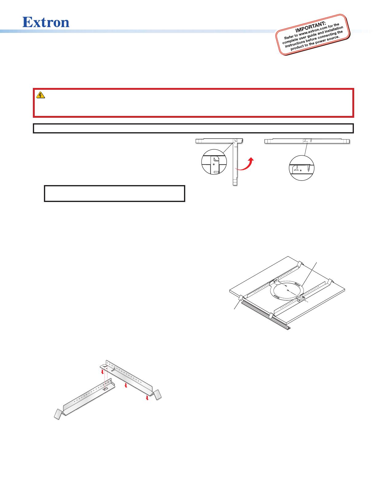
3. Attach two V-rails and one C-ring above the hole cut
in step 2, as described below.
a. Assemble two V-rail half sections so that they
become one single piece by tting the tab of
one end into the slot of the other end. Open the
V-rail until it locks together, as shown. Repeat this
procedure for the other V-rail.
b. Remove a ceiling tile adjacent to the tile with the
hole.
c. Place both assembled V-rails on the cut ceiling tile
and position them equally on either side of the hole.
The ends of the V-rails go over the ceiling grid.
d. Position the C-ring assembly on the two V-rails so
that the C-ring is centered over the hole.
C-ring
V
-rail
e. Secure the C-ring to the V-rails using two screws.
4. Route the speaker wires through the ceiling tile hole.
5. Configure the locking arms for thicker ceilings
(optional).
Four speaker locking arms are used to secure the
speaker to ceiling tiles up to 2.25 inches (5.72 cm) thick.
The locking arms are equipped with removable inserts
that accommodate ceiling tiles of up to 1.5 inches
(3.81 cm) in thickness. For ceiling tiles thicker than
1.5 inches, the locking arm inserts must be removed.
1
SF 26CT LP • Setup Guide (Continued)
Alternate
Knockout
Remove the
terminal cover.
c. Congure the cable/conduit access plate.
When not using conduit: Route the speaker
wires through the cable clamp.
When using conduit: Remove the cable clamp
and install the conduit into the access plate
opening. Secure the conduit to the plate with
the locking nut and pull the speaker wires from
the conduit.
d. Strip 0.2 inches (5 mm) from the wire ends.
e. Use one of the following three methods to attach
the speaker wires to the captive screw connector
(depending on the conguration).
Wiring Multiple Speakers in Parallel
When a chain of speakers is wired this way,
disconnecting
one speaker does not remove power from the remaining
speakers in the chain.
Number of Wires per
Connection Point
Maximum
Wir
e Gauge
1 12
AWG
2 16
AWG
4 18
AWG
Wire Gauge Table
Speaker 1
Speaker 2
IN
LOOP
IN
+
+
LOOP
+
+
(Black)
(Red)
(Red)
(Red)
(Black)
(Black)
Power Amplifier
Speaker 1
Speaker 2
(Black)
(Red)
(Red)
(Black)
Power Amplifier
(Black)
(Red)
Speaker 1
(Red)
(Black)
Power Amplifier
IN
LOOP
IN
+
+
LOOP
+
+
IN
LOOP
IN
+
+
LOOP
+
+
IN
LOOP
IN
+
+
LOOP
+
+
IN
LOOP
IN
+
+
LOOP
+
+
Wiring Multiple Speakers Using Loop-through
When a chain of speakers is wired this way,
disconnecting
one speaker removes power from all downstr
eam speakers.
Wiring a Single Speaker
1
2
3
2
To remove the insert:
a. Using a screwdriver, rotate the locking arm so that
the insert can be accessed
b. Use a small screwdriver to pry and separate the
insert from the locking arm, as shown below.
c. Repeat this process for the remaining three locking
arms.
d. Rotate all four locking arms back into the speaker.
6. Configure the cable/conduit access plate and
captive screw connector, as described below.
a. The cable/conduit access plate has one alternate
hole available covered by a knockout. This hole
may be used for loop out when using conduit. If this
knockout needs to be removed, do the following:
i. With the cable/conduit access plate still
attached to the speaker, place the tip of a at-
head screwdriver against the knockout.
ii. Lightly tap the screwdriver with a hammer to
remove the knockout.
b. Loosen the three cable/conduit access plate screws
and remove the cover.
Number of
Wires per
Connection
Point
Maximum
Wire
Gauge
1 12 AWG
2 16 AWG
4 18 AWG
3
ATTENTION:
Do not tin the wire leads before installing
into the connector. Tinned wires are not
as secure in the connector and could be
pulled out.
Ne pas étamer les conducteurs avant de
les insérer dans le connecteur. Les câbles
étamés ne sont pas aussi bien xés dans
le connecteur et pourraient être retirés.
f. Insert the captive screw plug into the four-pole
receptacle of the speaker.
Using a cable clamp:
g. Using a conduit adapter:
h. Replace the cable/conduit access plate and tighten
the three screws.
i. Tighten the cable clamp if it was used.
7. Mount the speaker
The speaker can be installed into rigid material (mineral
tile, gypsum board, sheetrock, etc.) or soft material, such
as berglass.
a. Insert the speaker through the bottom of the hole in
the ceiling tile that was cut in step 2 with the wires
out of the way.
b. Clamp the speaker to the C-ring by using a Phillips
screwdriver to tighten the four locking arms to the
C-ring.
NOTE: The screw hole locations are marked on
the front baffle
with a Phllips
head screw
symbol. Use
these holes to
tighten the locking
arms.
Tightening the locking arms into rigid material:
8
Ω
8Ω
6
4W
32W
OFF
8
W
16W
64W
32W
16W
OFF
10
0 V
7
0 V
NOTE: Each of the four locking arm screws
uses an Opti-Torque
TM
indicator. The indicator
releases a red plastic ring onto the screwdriver
once the screw is tightened to the correct
torque. Stop tightening any further when this
occurs to avoid overtightening the locking
arms to the C-ring.
ATTENTION:
To avoid damaging the speaker, do not
overtighten the four locking arm screws.
Pour éviter d’endommager l’enceinte, ne
serrez pas trop les quatre vis.
8Ω
64W
32W
OFF
8W
16W
64W
32W
16W
OFF
100 V
70 V
Tightening the locking arms into soft material:
Because berglass ceilings and other soft
materials are not as rigid as mineral tiles and
other hard materials, the Opti-Torque indicator
should not to be used as a tightening guide due to
the risk of overtightening.
Locking arm
screw hole
marking
4-pole
Captive Screw
Connector
Flexible Conduit Adapter
SF 26CT LP • Setup Guide (Continued)
© 2016-2020 Extron Electronics All rights reserved. All trademarks mentioned are the property of their respective owners. www.extron.com
Adjust the Tap Selector
8
Ω
8
6
4
W
3
2
W
O
F
F
8
W
1
6
W
6
4
W
3
2
W
1
6
W
O
F
F
100
V
7
0 V
8Ω
64W
32W
OFF
8W
16W
64W
32W
16W
OFF
100 V
70 V
10. Install the grille. Position the grille so that it covers the
bafe of the speaker. Six small magnets secure the grille
in place.
Speaker Grille
8
Ω
8
6
4
W
3
2
W
O
F
F
8
W
1
6
W
6
4
W
3
2
W
1
6
W
O
F
F
100
V
7
0 V
ATTENTION:
When setting the taps for a distributed
(high impedance) system, do not tap the
system above the rated power of the
amplier.
When connecting multiple speakers in
8-ohm mode, be sure that the combined
rated impedance does not equal a value
less than the minimum rated impedance
of the amplier.
Lors de la mise en place des capteurs
pour un système distribué (haute
impédance), n’exploitez pas le système
au delà du niveau d’alimentation de
l’amplicateur.
Lors de la connexion de plusieurs
enceintes en mode 8 ohm, assurez vous
que le niveau d’impédance combinée
ne soit pas équivalent à une valeur
inférieure à l’impédance minimum de
l’amplicateur.
4
ATTENTION:
To avoid damaging or deforming soft
ceiling material, tighten the locking
arms to secure the speaker, but short
of causing the speaker to deform the
at mounting surface of the ceiling,
as seen from below.
An de ne pas endommager ni
d’altérer un plafond souple, serrez les
bras de verrouillage pour sécuriser
l’enceinte, en veillant cependant à
ce que l’unité ne cause l’altération
de la surface de montage plane du
plafond, comme illustré ci-dessous.
8. If required, attach a secondary support line.
a. Connect a secondary support line to the support loop
on the back of the speaker enclosure, as shown here.
Anchor end to suitable
secure points within the
solid and permanent
building structure.
ATTENTION:
Do not allow any slack in the secondary
support line.
Ne laissez pas de mou au niveau du lin de
sécurité secondaire.
b. Replace the adjacent tile that was removed in
step 3.
9. Set the rotary tap selector switch to the appropriate
setting using a small screwdriver.
X
68-3443-50 Rev. A
06 20
  • Page 1 1
  • Page 2 2
  • Page 3 3
  • Page 4 4

Extron SF 26CT LP User manual

Type
User manual

Extron SF 26CT LP is a low-profile XD 2-way speaker designed for installation in suspended ceilings. It features a plenum-rated assembly, making it suitable for use in air handling spaces. The speaker can be installed by a single trade or multi-trade procedure. It has a captive screw connector for easy wiring and can be configured for 8-ohm or 70/100-volt distributed systems. The SF 26CT LP comes with a cutout template for precise installation and includes four locking arms for securing the speaker to ceiling tiles up to 2.25 inches thick.

Ask a question and I''ll find the answer in the document

Finding information in a document is now easier with AI

in other languages