Page is loading ...

1000 W. Wilshire Blvd., Suite 362 y Oklahoma City, Oklahoma 73116 y Phone: 405.848.3108 y Fax: 405.848.3217 y www.altecpro.com
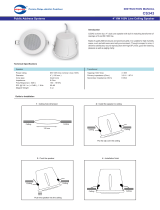
SLC308-8T
Preassembled Ceiling Speaker System
FEATURES – THE ALTEC LANSING DIFFERENCE
• High Efficiency – 97 dB SPL
• High Output – 109 dB Peak SPL (8 watt Tap)
• Preassembled Speaker System for Quick Installation
• Off-White Décor Snap-On One Piece Metal Grille
• 5-Position Switch for Easy Transformer Tap Selection
• ½ in. (13 mm) Conduit Connector
• Metal Tile Bridge Included
GENERAL PRODUCT DESCRIPTION
High labor costs are driving the development of a new generation
of preassembled, quick-install ceiling speaker systems. Altec
Lansing’s SLC308-8T builds on the company’s strength as one of
the world’s leading supplier of premium 8 in. (203 mm) Duplex
®
ceiling speakers equipped with premium, low-insertion loss
transformers.
The SLC308-8T features Altec’s best selling CD308-8T component.
The CD308 is an 8 in. (203 mm) Duplex
®
component rated at 16W
AES / 64W peak power handling. The 8 watt 70V/100V
transformer has a broadband insertion loss of < 0.6 dB from 50 Hz
to 15 kHz.
Altec’s high efficiency Duplex
®
design delivers maximum output
with minimum amplifier power. At a broadband efficiency rating
of 97 dB SPL (1W/1m), the SLC308-8T has rated peak output of
109 dB SPL using the 8 watt transformer tap at a distance of one
meter. Less efficient ceiling speaker systems require 30W to 60W
transformer taps to generate similar output. The high efficiency
design of the SLC308-8T allows the systems integrator to
downsize the amplifier channel assigned to each zone of ceiling
speakers by a factor of two-thirds or more. Using the SLC308-8T
is the most profitable choice a sound contractor can make.
The CD308-8T is installed in a round, metal, dampened 0.25
cubic foot enclosure with metal strain relief strap. Three metal
dogleg arms are screwed-down to secure the enclosure to the
included metal tile bridge. An off-white one-piece metal décor
grille snaps into the assembly. The SLC308-8T has a two-wire
input connection (red & black), making it fool-proof for even the
least experienced installers. The ½ in. (13 mm) connector easily
mates to either metal or flex conduit.
Installers particularly like Altec’s package. The mounting hole in
the metal tile bridge serves as a hard template for cutting a
perfect hole in the ceiling tile. A metal S-hook allows the
installer to hang the enclosure from the ceiling grid of flex-
conduit while wiring up the SLC308-8T.
In addition to industry-leading efficiency and output, the SLC308-
8T is among the most lightweight packages available to sound
contractors. The low-profile design allows the SLC308-8T to fit
into tight ceiling spaces. An optional ring (SLC-RING) is required
for plaster or sheetrock ceilings.
NOTE: SHIPPED IN PAIRS
SPECIFICATIONS
FREQUENCY RESPONSE
1, 2
130 Hz – 20 kHz (±5 dB)
USABLE LOW FREQUENCY LIMIT (-10 dB)
1, 2
110 Hz
SENSITIVITY
3
97 dB SPL
POWER HANDLING
4
16 W AES (continuous); 64 W peak
PEAK OUTPUT (1 m)
5
115 dB SPL; 109 dB SPL (8W transformer tap)
COVERAGE ANGLES
6
90º (horizontal) by 90º (vertical)
DIRECTIVITY FACTOR, Q
6
11.91
DIRECTIVITY INDEX, DI
6
10.76 dB
TRANSDUCER COMPONENTS
LF: 1 x 8-in. (203 mm), low frequency woofer
HF: 1 x 3-in. (76 mm), high frequency tweeter
IMPEDANCE
7
Nominal: 8.0 ohms
Minimum: 7.3 ohms at approximately 7.5 kHz
CROSSOVER FREQUENCY
Passive LF - HF: 3,000 Hz
TRANSFORMER
Premium 8 watt 70V/100V, switch selectable taps of 8W, 4W,
2W, and 1W; rated at < 0.6 dB insertion loss, 50Hz – 15 kHz
INPUT CONNECTIONS
Only 2 wires, pre-stripped, for simple, quick installation
FINISH
Enclosure - Black Painted Steel with internal damping material
Grille – Matte White Décor Round Metal Grille
DIMENSIONS
Diameter: Can - 9.31 in. (236 mm); Baffle – 11.75 in. (298 mm)
Grille – 12.75 in. (324 mm)
Depth: Can – 7.85 in. (199 mm)
Length/Width: Tile Bridge – 23.75 in. (603 mm) / 14 in. (356 mm)
NET WEIGHT
8.5 lbs. (3.86 kg), one speaker system with grille
SHIPPING WEIGHT
31.7 lbs. (14.38 kg), (includes 2 speaker systems with grilles and tile bridges)
CD308-8A – THEILE-SMALL PARAMETERS
Free Air Resonance, ƒ
S
: 92.2 Hz
Equivalent Volume Compliance, V
AS
: 0.84 ft.
3
(23.7 l)
Total Q, Q
TS
: 0.87
Electrical Q, Q
ES
: 1.05
Mechanical Q, Q
MS
: 5.26
D.C. Resistance, R
E
: 8.0 ohms
Peak Linear Displacement, X
max
: 0.05 in. (1.3 mm)
Reference Efficiency, η
o
: 2.13%

INSTALLATION AND WIRING
Although the SLC308-8T can be mounted into a sheetrock or
plaster ceiling, the following installation procedure is intended
for suspended tile ceilings. Note: We recommend that you order
the mounting ring (SLC-RING), not included, when installing the
SLC308-8T into a sheetrock or plaster ceiling.
1. Place ceiling tile, finished side facing up, over the flat, 12 in.
(305 mm) to 22 in. (559 mm) diameter opening of a container
such as a Rubbermaid
®
32 gallon Brute
®
model 2632.
2. Locate the approximate center of the mounting hole that is to
be cut, and mark this spot on the ceiling tile. Note: This
center can be located anywhere along the length of the
ceiling tile that is at least 8 in. (203 mm) from either end and
equidistant from each side edge.
3. Align the center of the 10.75 in. (273 mm) tile bridge hole
with the spot marked as the center, and position the metal
tile bridge flat against the ceiling tile with the ends of the tile
bridge aligned to the side edges of the ceiling tile.
4. Carefully, so as not to damage the ceiling tile, temporarily
secure the tile bridge in-place with adjustable torsion clamps
such as C-clamps.
5. Guide the blade of a RotoZip
®
RZ01, or similar rotary cutting
tool, against the edge of and completely around the 10.75 in.
(273 mm) tile bridge hole, cutting the ceiling tile hole.
6. Remove the torsion clamps and tile bridge from the ceiling
tile.
7. Install the ceiling tile in the ceiling’s T-grid.
8. Install the tile bridge on top of the ceiling tile, and align the
tile bridge hole with the newly cut ceiling tile hole.
9. Pull the wiring and or flex conduit through the tile bridge and
ceiling tile holes.
10. Attach one end of the S-hook to the SLC308-8T’s metal strain
relief strap and rest the other end of the S-hook, through the
mounting hole, on the top surface of the tile bridge.
11. Connect the audio transmission (-) wire (usually black) to the
black wire of the SLC308-8T, and connect the audio
transmission (+) wire to the red wire of the SLC308-8T. Secure
a sufficient insulator cover over these connections. Note:
Proper rated wire-nuts are recommended to insulate these
connection points.
12. If flex conduit is used, pack the excess wire into the conduit
(including the wire nuts), and secure the flex conduit with the
½ in. (13 mm) connector.
13. Remove the S-hook and gently push the SLC308-8T (and
excess conduit or wire) up into the hole and tighten the three
mounting screws, causing the dogleg arms to swing out and
anchor the enclosure to the metal tile bridge.
14. Snap on the metal grille.
ARCHITECT’S AND ENGINEER’S SPECIFICATIONS
The loudspeaker system shall be an in-ceiling design, consisting
of a Duplex
®
8 in. (203 mm) diameter cone woofer and a 3 in. (76
mm) diameter cone tweeter. This loudspeaker component shall
have a power rating of 16W AES (64W peak). The loudspeaker
system shall have an operating bandwidth of 130 Hz to 20 kHz,
with a sensitivity of 97 dB at one watt, when measured at one
meter. The loudspeaker system shall include a 5-position switch
for adjustable load/output requirements. The switch shall
terminate the two 18 gauge input wires directly to the nominal 8
ohm impedance of loudspeaker component, or indirectly to the
loudspeaker component through a step-down, multi-tap 8W
transformer. This transformer shall have an insertion loss of < 0.6
dB. The loudspeaker component, switch and transformer shall be
assembled into a moisture resistant black-painted steel enclosure
with internal damping material. The enclosure diameter shall be
9.31 in. (236 mm), the enclosure’s baffle diameter shall be 11.75
in. (298 mm), and the enclosure’s depth shall be 7.85 in. (199
mm), including the ½ in. (13 mm) flex-conduit connector. The
loudspeaker system shall include a 12.75 in. (324 mm) diameter,
one-piece, snap-on, off-white-painted steel grille; and a 23.75 in.
(603 mm) long, 14 in. (356 mm) wide, 20 gauge galvanized steel
tile bridge. The loudspeaker system shall be the Altec Lansing
Professional model SLC308-8T.
SPECIFICATION NOTES
1
The frequency response of the loudspeaker system is measured at a distance of no less than 3 meters to obtain full range data. The
level is then corrected to be equivalent to a 2.83 V 1 m measurement. A near field measurement of the system is performed for
frequencies below 500 Hz. This data is then combined with the full range measurement to give an accurate composite frequency
response curve.
2
The limits of the frequency response are referenced to -5 dB of the loudspeaker’s rated sensitivity in the SLC’s 0.25 ft.
3
sealed
enclosure.
3
The sensitivity of the loudspeaker system is the log based average SPL taken over the intended bandwidth of operation for the system
with a 2.83 V swept sine stimulus. The data is measured and level corrected in a manner consistent with note 1.
4
The power handling capacity of the loudspeaker system is tested using a full range form of AES Standard 2-1984. The test stimulus is
band limited (40 Hz – 16 kHz) pink noise with a 6 dB crest factor. The applied RMS voltage is determined using the minimum impedance
of the system. The amplifier used to drive the loudspeaker has a minimum operating headroom of 6 dB referenced to the RMS voltage.
5
The peak output level of the system is calculated based on the sensitivity and the peak power handling capabilities of the system.
6
The coverage angles for the loudspeaker are taken as the -6 dB points of the directivity response and averaged from 500 Hz to 16 kHz.
7
The minimum impedance of the loudspeaker is taken over its intended band of operation.
As we are continually striving to improve Altec Lansing products, specifications are subject to change without notice.
VISIT WWW.ALTECPRO.COM FOR
• Authorized EASE data on all Altec Lansing Professional loudspeakers
• PDF specification sheets. Download page 1 of the specification sheet for you submittals.
• One paragraph A&E Specifications in .doc format
• The latest information on Altec Lansing Professional products.
• Performance specifications for the CD308-series speakers, including the one-octave polar response charts.
© 2004 Altec Lansing Professional y 1000 W. Wilshire Blvd., Suite 362 y Oklahoma City, Oklahoma 73116
Phone: 1.405.848.3108 y Fax: 1.405.848.3217 y Email: pr oinfo@alteclansing.com
Revision 01
20 50 100 200 500 1 k 2 k 5 k 10 k 20 k
Frequency (Hz)
60
70
80
90
100
110
dB SPL (ref: 20 Pa)
Frequency Response
/