Page is loading ...


© 2018 Digital Monitoring Products, Inc.
Information furnished by DMP is believed to be accurate and reliable.
This information is subject to change without notice.
Silencing an Alarm
When the alarm bell or siren is sounding, enter your user code or present
your card to a keypad or reader during the Status List display.
IS THIS A FALSE ALARM? YES NO or CANCEL VERIFY displays.
• If a burglar alarm is valid, press NO or VERIFY to send a verify message
to the Central Station. The system will remain armed.
• If a valid alarm has not occurred, press YES or CANCEL to cancel the
alarm and send an Abort or Cancel message to the Central Station
and the security system will be disarmed.
Note: For Area Systems, this prompt is displayed only if the User Code has
the authority to disarm the area.
What to do when a trouble tone is sounding
You can silence the trouble tone by pressing any key. This only silences the
keypad and does not correct the condition that originally caused the problem.

XT30/XT50 User Guide i
XT Series
™
User Guide
for XT30/XT50 Series Panels
Table of Contents
Section Page Section Page
Introduction ..............................................................1
About Your Security System .............................................1
Emergency Evacuation Plans ............................................ 2
Keypads .........................................................................3
Common Keys on All Keypads...........................................5
Number Pad ....................................................................6
Standard Keyboard .......................................................... 6
Keypad User Options .......................................................7
Special Keypad Tones ......................................................7
1100 Series Wireless .......................................................8
Special Wireless Displays .................................................9
Special Keypad Displays ...................................................9
Email/Cell Phone Messages ............................................ 10
MyAccess™ Text Messaging CMDs .................................. 10
Understanding Security System Terms ............................ 10
Arming and Disarming .............................................13
How Your System Operates ............................................ 13
Arming Functions .......................................................... 13
Key Fob Arming ............................................................. 14
Key Fob Disarming ........................................................ 14
Area System Arming ...................................................... 14
Area System Disarming .................................................. 15
All/Perimeter System Arming .......................................... 16
All/Perimeter System Disarming ...................................... 17
Home/Away System Arming ........................................... 19
Home/Away System Disarming ....................................... 20
Keypad Shortcut Keys .................................................... 21
User Menu ...............................................................23
Accessing the User Menu ............................................... 23
User Menu Options ........................................................ 23
User Check-In ............................................................... 24
Zone Activity Check ....................................................... 24
Sensor Reset ................................................................. 25
Outputs On/Off ............................................................. 25
Favorite ........................................................................ 26
Z-Wave Setup ............................................................... 26
Wi-Fi Setup ................................................................... 32
Zone Monitor ................................................................ 34
Using the Zone Monitor Function .................................... 35
System Test .................................................................. 35
User Codes ................................................................... 36
Schedules ..................................................................... 39
Extending Schedules ..................................................... 40
Output Schedules .......................................................... 40

ii XT30/XT50 User Guide
Favorite Schedules ........................................................ 41
Date and Time .............................................................. 42
Request Service? ........................................................... 43
System Setup Record..................................................... 44
Protection Areas ............................................................ 44
Output Record .............................................................. 44
System Setup ..........................................................44
Z-Wave Device Name ..................................................... 45
Favorite List .................................................................. 46
Key Fob Button Programming ......................................... 47
User Codes ................................................................... 47
About the Display Events Section.................................... 49
Zone Activity Check Event Display .................................. 49
Zone Bypass Event Displays ........................................... 49
Appendix A ..............................................................49
Zone Event Displays ...................................................... 50
Arming and Disarming Event Displays ............................. 50
User Check-In Event Displays ......................................... 50
User Code Change Event Displays .................................. 50
Supervisory Event Displays ............................................ 51
System Monitor Event Displays ....................................... 51
Wireless Jamming Event Displays ................................... 51
Wireless Trouble Event Displays ...................................... 51
Appendix B ..............................................................52
1100 Series Wireless Description ................................... 52
Appendix C ..............................................................53
User’s Guide ................................................................. 53
Entering User Names .................................................... 55
Appendix D ..............................................................56
Email/Cell Phone Message User’s Guide .......................... 56
MyAccess™ Text Messaging CMDs .................................. 57
PhoneAccess™ User’s Guide ........................................... 60
Common Keypad Displays .............................................. 61
Quick Reference Wallet Cards ................................. 65
Quick Reference Wallet Cards ................................. 65

Introduction XT30/XT50 User Guide 1
Introduction
About Your Security System
Your system is designed with your safety and comfort in mind. It uses
the latest in computer technology to create the most advanced,
user friendly, security, re, and access control system available.
The system combines ease of use with a simple to understand
keypad display to offer the full range of features requested by
today’s security system owners. Your security system can protect
both the interior and perimeter of your home or business while you
are away or just the perimeter when you are inside, giving you a
wall of security and peace of mind.
You can turn portions of your protection on or off at any time by
pressing a few keys. You can add, delete, and change personal user
codes at any time or check the status of all protection devices in
the system.
Keypads
This is the device we have placed at certain locations throughout
the premises that allows you to turn the system protection on and
off using your personal user code.
Keypad User Menu
The keypad provides a simple User Menu containing all of the
functions you need to fully operate your system such as changing
the time of day or a personal user code.
A Note About False Alarms
One of the most important concerns facing the security industry
today is false alarms. The accidental dispatching of police and
re agencies places others in jeopardy by limiting the response
capability of those emergency service units.
As part of our commitment to reducing false alarms, we would like
to encourage you to read this guide thoroughly. All the information
contained here can help you quickly, and comfortably, learn the XT
Series™ system operation.
Note: There may be a 30-second alarm communication delay
pre-programmed at installation to allow disarming if a false
alarm occurs. This delay is optional and can be removed or
increased to 45 seconds by your alarm dealer.
Test Your System Weekly
It is recommended that you test the burglary portion of your system
at least once each week. Testing should involve an active test of all
doors, windows, and motion detectors connected to your system. If
your system also has re protection, call the service department to
nd out how this portion of your system should be tested.
Refer to the System Test section of this guide for instructions on
testing the burglary portion of your system.

2 XT30/XT50 User Guide Introduction
Practice your escape plans
Devising an escape plan is only the beginning. For the plan to be
effective everyone should practice escape routes from each room.
Second Floor
Building Front
Building Back
First Floor
Fire Escape
Window Ladder
Figure 1: Sample Escape Route Map
Early detection
The best way to survive a re or other emergency is to get out
early. A re alarm system installation, with smoke and carbon
monoxide detectors in each room, can greatly decrease your risk
of loss or injury.
Emergency Evacuation Plans
Overview
The National Fire Protection Association recommends that you
establish an emergency evacuation plan to safeguard lives in the
event of a re or other emergency.
Draw a oor plan of your home or business
On a clean sheet of paper, draw the walls, windows, doors, and
stairs. Also draw any obstacles that a person may encounter while
exiting the building such as large furniture or appliances.
Develop escape routes
Determine at least two routes the occupants in each room can
take to safely escape. One route can be the most obvious such as
the door. Another can be through an easily opened window. If the
window is high off the ground, an escape ladder should be provided.
Draw arrows on the oor plan to show escape routes from each
room.
Decide where to meet
Prearrange a meeting place outside and away from where
emergency personnel are likely to be working. A neighbor’s house
or across the street in front of the house are good locations. Always
perform a head count to make sure all occupants safely exited.
NEVER ENTER A BURNING BUILDING. If the head count shows one
or more persons missing, give this information immediately to the
authorities. Never enter a building to look for someone.

Introduction XT30/XT50 User Guide 3
Keypads
Your system may have one or more easy to use LCD keypads that allow you to properly operate the system.
32-Character Display
Armed LED
Power LED
Data Entry Digit keys
COMMAND Key
Back Arrow Key
Select Keys
1 2 3 4
9 0 CMD
5 6 7 8
ABC PRINTING
FRI 2:51 AM
Backlit Logo
and Proximity
Antenna
Thinline™/Aqualite™ Keypad
Icon Display
Shortcut and Digit keys
Backlit Logo
and Proximit
y
Antenna
COMMAND Key
Back Arrow Key
Select Keys
Thinline™ Series Icon Keypad
32-Character Display
Data Entry Digit keys
COMMAND Key
Back Arrow Key
Select Keys
Backlit Logo
and Proximity
Antenna
SMITH RESIDENCE
FRI 12: 51 PM
Thinline™ Wireless Keypad
Graphic Touchscreen Keypad
1 2 3 4
5 6 7 8
9 0
CMD
ABC DEF GHI JKL
MNO PQR STU VWX
YZ
TO DAY
WEDNESDAY
82
98 77
CURRENT
HI LO
85 68
HI LO
98 77
Panic
Chime
Reset
Favorites
DISARMED
Dealer Logo
Interactive Shield
Local Weather
Conditions
Proximity Card
Reader
Carousel Menu

4 XT30/XT50 User Guide Introduction
Select Keys and Select Areas
Thinline™, Aqualite™, Icon and Wireless Keypads:
There are four keys under the display called the select keys. On
Graphic Touchscreen keypad these are referred to as the select
areas. These keys are one of the features that make your system so
easy to operate. They allow you to make selections by pressing the
select key or area under a choice shown in the display.
Note: For the purposes of this guide, when instructed to press the
rst select key, press the far left select key; the second select key
is the second from the left; third select key is second from the
right; and the fourth select key is the far right key.
Graphic Touchscreen Keypads:
There are four Select Areas in the display. These select Areas are
one of the features that make your system so easy to operate. They
allow you to make selections by touching the area to choose the
item in the display.
Note: For the purposes of this guide when using Graphic Touchscreen
Keypads, when instructed to press the rst select key, touch select
area 1; the second select key touch select area 2; third select key
touch select area 3; and the fourth select key touch select area 4.
Power/Armed LED
Thinline™ and Aqualite™ Keypads:
The Power LED indicates the panel Power status. It is recommended
you contact the service department when the Power LED is off or
blinks.
The Armed LED is ON steady anytime any burglary protection
area is armed and is OFF when ALL areas are disarmed.
LED Operation AC Battery
ON (Steady) OK OK
OFF Trouble N/A
BLINKS OK Trouble
Graphic Touchscreen Keypads:
The LED indicates the Power and Armed status of the panel.
Depending on the operation, the LED displays in Red or Blue as
listed in the table.
Color and Activity LED Operation
Blue Steady Panel Disarmed, AC Power OK, Battery OK
Blue Blinking Panel Disarmed, AC Power OK, Battery Fault
No Light Panel Disarmed, AC Power Fault, Battery OK
Red Steady Panel Armed, AC Power OK, Battery OK
Red/Blue Alternate Panel Armed, AC Power OK, Battery Fault
Red Blinking Panel Armed, AC Power Fault, Battery OK
32-Character Display
Select Area 1
Select Area 3
Select Area 2
Select Area 4
Touch Select Areas

Introduction XT30/XT50 User Guide 5
Power/Armed Logo
Thinline™ Wireless Keypads:
The backlit logo on the keypad
indicates the keypad Power status
and Armed status of the panel. Depending on the operation, the
logo displays Red or Green as listed in the table.
Color and Activity Armed Status Keypad Power Status
Green Steady Panel Disarmed AC Power OK, Battery OK
Green Blinking Panel Disarmed AC Power OK, Battery Fault
No Light Panel Disarmed AC Power Fault, Battery OK
Red Steady Panel Armed AC Power OK, Battery OK
Red/Green Alternate Panel Armed AC Power OK, Battery Fault
Red Blinking Panel Armed AC Power Fault, Battery OK
Panic Functions
Your keypad may be set up to send a Panic, Emergency, or Fire
report to the central station. This function is optional. If this option
is programmed for your keypad, icons display below the top row
select keys or areas.
Thinline™, Aqualite™, Icon and Wireless Keypads
Press and hold the two select keys adjacent to the desired icon
for 2 seconds, until a beep from the keypad is heard.
Top Row Select Keys
Police Emergency Fire
Shaded Keys To Indicate the Police Panic Function
7/0 Panic Function
Thinline™ and Aqualite™ Keypads may also be programmed
at installation to allow the user to initiate an optional Panic
alarm by simultaneously pressing and holding the 7 and 0 (zero)
keys. When the 7 and 0 keys are pressed, the keypad sends a
panic report to the central station. The 7/0 Panic Function is
not available on Thinline Icon, Wireless, or Graphic Touchscreen
Keypads.
Graphic Touchscreen Keypads
Press Panic in the carousel menu and press the desired icon for
2 seconds until a beep is heard.
Graphic Touchscreen Keypad Panic Functions
Common Keys on All Keypads
Data Entry Digit Keys
These keys allow you to enter your user code when arming
or disarming your system or enter other information into the
keypad.
CMD key
The CMD key allows you to advance through the keypad displays,
the User Menu, or complete a data entry function.
Back Arrow (<—) key
The Back Arrow (<—) allows you to go back through the keypad
displays or to erase the last character you entered.
PANIC OPTIONS
POLICE EMERGENCY FIRE

6 XT30/XT50 User Guide Introduction
Number Pad
1. Choose a character from the table.
2. Identify the Number the character correlates with and
press that number on the number pad.
3. Identify the Select Key or Area for that character and
press that select key or area on the keypad. To access
the lowercase letter, press that select key or area again.
4. When the desired character displays on the keypad,
return to Step 1 to enter another character or press CMD
if nished.
NUMBER
SELECT KEY OR AREA
1 2 3 4
1 A B C ( [ {
2 D E F ) ] }
3 G H I ! ^ ~
4 J K L ? “ |
5 M N O / \ `
6 P
Q
R & $
7 S T U @ %
8 V W X , =
9 Y Z space, : _ ;
0 -, + ., ‘ *, < # >
Standard Keyboard
• Press ABC to access uppercase letters.
• Press abc to access lowercase letters.
• Press !@# to access symbols.
• Press 123 to access the number pad.
Number Pad and Select Keys
1 2 3 4
5 6 7 8
9 0 CMD
A
C
B
D
F
E
G
I
H
J
L
K
V
X
W
S
U
T
P
R
Q
M
O
N
Y
Z
E
N
T
E
R
B
A
C
K
Key
1
Key
2
Key
3
Key
4
Standard Keyboard and Select Areas
1 2 3 4
5 6 7 8
9 0
CMD
ABC DEF GHI JKL
MNO PQR STU VWX
YZ
ABC
!@#
123
q w e r t y u i
o p
a s d f g h j k l
z
x c v b n m CMD
Area
1
Area
2
Area
3
Area
4

Introduction XT30/XT50 User Guide 7
Volume
On LCD Keypads at SET VOLUME LEVEL, use the left select key
to lower the volume. Use the right select key to increase the
volume. On Thinline™ Icon Series keypads, enter the desired
speaker volume level from the range of off (0) to maximum (8).
On Graphic Touchscreen Keypads, press the minus button to
decrease the keypad volume and the plus button to increase
the keypad volume. During an alarm, trouble, and prewarn
conditions, the volume is always at maximum level.
Model Number
The keypad model number, rmware version, and date display.
Serial Number
The serial number assigned to the keypad displays. Press the
back arrow key to exit the User Options function.
Keypad Address
The current keypad address assigned to the keypad displays.
Press the back arrow key to exit the User Options function.
Carousel Edit Menu
On Graphic Touchscreen Keypads you can choose what displays
in the carousel menu on the home screen. Press a box under
Display In Menu and a check mark appears indicating that item
will display in the carousel menu. Deselect the box to remove
the item from the carousel menu.
Special Keypad Tones
Your keypad contains a small speaker that alerts you about events
as they occur on your system. For burglary alarms, the tone will
silence as soon as the rst user code digit key is pressed. If a valid
user code is not entered within 5 seconds or an invalid user code is
entered, the tone begins sounding again.
Keypad User Options
The User Options menu allows you to make adjustments to your
keypad to best t your environment and needs.
LCD Keypads:
Press and hold the back arrow and CMD keys at the same time for
two seconds. The keypad screen changes to SET BRIGHTNESS.
Press CMD to display the next option or the back arrow key to
exit.
Graphic Touchscreen Keypads:
Press Options in the carousel menu.
Brightness
On LCD Keypads at SET BRIGHTNESS, use the left select key to
lower the keypad brightness. Use the right select key to increase
the brightness. On Thinline™ Icon Series keypads, enter the
desired brightness from the range of off (0) to maximum (8). If
the brightness level is lowered, it temporarily reverts back to
maximum intensity whenever a key is pressed.
On Graphic Touchscreen Keypads, press the minus button to
decrease the keypad brightness and the plus button to increase
the brightness. If the brightness level is lowered, it temporarily
reverts back to maximum intensity whenever a key is pressed. If
the screen is not pressed, and the speaker has not sounded for
30 seconds, the user-selected standby brightness level restores.
Tone
On LCD Keypads at SET TONE, press the left select key to lower
the tone. Press the right select key to increase the tone. On
Thinline™ Icon Series keypads, enter the desired speaker tone
from the range of 1-8.
On Graphic Touchscreen Keypads, press the minus button to
lower the keypad tone and the plus button to raise the keypad
tone.

8 XT30/XT50 User Guide Introduction
Connect Keyring or Lanyard Here
LED
2-Button Layout 1-Button Layout
4-Button Layout
TOP
TOP
BTM
LFT
RGT
TOP
BTM
Key Fob Examples and
Button Names
Following are brief descriptions of the different tones you may hear
from the keypad.
Fire alert: An intermittent sweeping siren from LCD keypads that
continuously repeats until the alarm is silenced. This is in addition
to the bell output from the alarm panel.
Burglary alert: A siren tone from LCD keypads that continues until
the alarm is silenced. This is in addition to the bell output from the
alarm panel.
Key press tone: A short beep as you press a key on the keypad.
Prewarn tone: A continuous pulsed tone that sounds when you
open an entry delay door on a system that is armed (turned on)
reminding you to disarm the burglary protection.
Your system will silence the tone as soon as the rst user code
digit key is pressed. If a valid user code is not entered within 5
seconds or an invalid user code is entered, the prewarn tone begins
sounding again.
Exit tone: When fully arming your system to leave, a continuous
pulsing tone sounds during the exit countdown just after arming to
remind you to exit the premise. At ten seconds prior to the end of
the countdown, the rate of pulsing increases.
Monitor tone: A pulsed tone that sounds one time for one second
each time a door or window is opened while you are using the zone
monitor function from the User Menu. See Zone Monitor.
Trouble tone: A steady tone indicating a trouble condition on your
system. Press any key to silence the trouble tone.
What to do when the trouble tone sounds
You can silence the trouble tone by pressing any key.
This only silences the keypad and does not correct the
condition that originally caused the trouble.
1100 Series Wireless
Your system may include wireless devices such as key
fob(s). There are three types of wireless key fobs available:
4-Button Model 1144-4 Key Fob
2-Button Model 1144-2 Key Fob
1-Button Model 1144-1 Key Fob
The drawing shows the button
layout for all three models for your
reference. Each button on the key
fob is programmed to perform a
specic action. The button names
are listed for your reference.
TOP = the Key Fob Top button
BTM = the Key Fob Bottom button
LFT = the Key Fob Left button
RGT = the Key Fob Right button
The button programming list for the
key fob(s) connected to your system
is located in the System Setup section
of this guide. Refer to Appendix B for
LED Status operation information.
Specic function labels can be added
to each button to indicate button
operation.
For best operation, allow the LED
to turn on and then turn off before
pressing another button. The key
fob may not complete sending the
signal for the button press if another
button is pressed too soon.

Introduction XT30/XT50 User Guide 9
Special Wireless Displays
Your system may use wireless transmitters to send alarm and
trouble information from the protection devices to the panel.
Wireless systems have a few unique keypad displays.
BACK DOOR -LOBAT - (Low Battery) The battery in a wireless
transmitter is low. (BACK DOOR is used as an example only.)
BACK DOOR -MISNG - (Missing) The panel is not receiving the
wireless transmitter periodic test report.
WIRELESS -TRBL - (Trouble) Some part of your wireless system is
operating improperly. Call the service department for assistance.
WIRELESS RECEIVER JAMMED -ALARM - Your system may be
programmed for wireless interference detection and, if displayed,
your wireless receiver has detected an interfering signal while the
system is armed.
WIRELESS RECEIVER JAMMED -TRBL - (Trouble) Your system may be
programmed for wireless interference detection and, if displayed,
your wireless receiver has detected an interfering signal while the
system is disarmed.
Special Keypad Displays
As you use your system, you may occasionally see a keypad display
that asks you to enter a user code or describes a condition on the
system. Below are some examples of the displays you may see.
ALARM
A 24-hour zone, such as a re or panic zone, or an armed burglary
zone is faulted. Your system may sound bells or sirens.
ALARM NOT SENT
The alarm signal was aborted and was not sent to the central station
because a user code was entered to disarm the system before the
alarm signal was sent to the central station. Also, your system may
be pre-programmed at installation to send an Abort signal to the
Central Station. Refer to the Introduction section.
ALARM CANCELLED
An Alarm signal just sent to the central station was cancelled
because a user code was entered after the alarm was sent. Also, an
Alarm Cancel signal is sent to the Central Station.
ALARM VERIFIED
A valid burglar alarm has occurred and has been manually veried
by the user. The alarm system also transmits a VERIFY message to
the Central Station.
ENTER CODE
The system requires you to enter a personal user code. User codes
can be used for turning your system on (arming), turning your
system off (disarming), and other system options.
As you enter your user code, the keypad display shows an asterisk
(*) in place of each digit pressed. This prevents others from seeing
your user code on the display as you enter it.

10 XT30/XT50 User Guide Introduction
Understanding Security System Terms
Throughout this guide, and in some displays on your keypad, you
may see certain words or phrases that might be unfamiliar.
Below are some terms you will see here and on the keypad display.
Arming
This is the term used for turning on the burglary protection in one
or more areas of the system. Your system may require you to enter
a user code. When armed, the system can sound alarm bells or
sirens and, if monitored, send alarm reports to a central station
when a burglary zone is faulted.
Fire, panic, and other 24-hour devices are always turned on and do
not need to be armed.
Disarming
This means turning off one or more areas of the system. When
disarmed, the system does NOT sound alarms or send alarm reports
to a central station when a burglary zone faults.
Zone
A zone refers to one or more protected openings or pro tection
devices assigned the same zone number. Each door or window,
motion detec tor, smoke detector, or other device has a zone
number and a name.
Often, similar devices in the same general area share the same
zone. For example, the windows on the east side of the premises
can all be grouped together in a zone named E. WINDOWS.
Entry or Exit Zone
Almost all systems have one or more doors through which you can
enter or exit the premises. These doors are programmed with a
delay time to allow you to enter or exit while the system is armed
without setting off the alarm.
TRY AGAIN or INVALID CODE
The code entered is not recognized by the system. Check the user
code and try again.
TRBL (TROUBLE)
There is a problem with a protection device or system component.
This display is accompanied by a description of the problem.
SYSTEM TROUBLE or SERVICE REQUIRED
There is an electronic failure in your system. Contact the service
department as soon as possible.
TEST IN PROGRESS
The system is currently being tested by an installation or service
technician.
Email/Cell Phone Messages
Your system may be programmed at installation to send a variety of
messages to your personal email, and cell phone.
The message option uses your security system’s reporting capability
to send reports using an email address or cell phone number in
much the same way as someone sending an email would do. You
can receive reports of alarms, troubles, or system armings and
disarmings and know at a glance your system status. See Appendix
D for more information.
MyAccess™ Text Messaging CMDs
Your system may be programmed to allow simple text messages to
be sent to the security system and perform basic user operations.
By texting a message from your cell phone or PDA, the following
actions can be performed: Arm/Disarm, check Armed Status, Cancel
Alarm, and turn Outputs On/Off. Other operations that may be
programmed from your cell phone or PDA include: Turning on and
off lights, Locking and unlocking doors, and Setting the thermostat.
See Appendix D for more information.

Introduction XT30/XT50 User Guide 11
When you arm the system, activity on all burglary zones is ignored
until the programmed exit delay time expires. Once that time has
expired and the system is fully armed, opening the door causes the
panel to start the entry delay time. During the entry delay time,
enter a valid user code to disarm the system or an alarm occurs.
Instant Zone
Exterior windows and non-entry doors, or interior protection
devices, are typically not programmed with delay times. If these
zones fault while the system is armed, an alarm occurs instantly.
24-Hour Zone
A 24-hour zone is not turned on or off by arming or disarm ing your
system. Some examples of 24-hour zones are re zones, panic
zones, and temperature control zones.
Areas
An area is made up of burglary zones that can be armed or disarmed
together. The Perimeter area, for example, consists of all the doors
and windows on the outside of the building. When you arm the
Perimeter, these zones sound an alarm if tripped.
Central Station Monitoring
Your system can also be programmed to automatically send alarm,
trouble, and arming and disarming reports to a central station.
Operators at the central station can then dispatch the appropriate
authorities or contact you with the specic event information.
Status
Status is a feature that automatically displays the system armed
or dis armed status on the keypads. Alarm or trouble con ditions on
a zone or a system monitor such as AC or battery trouble can also
display. There are two types of status information available: Status
List and Armed Status.
Status List
The keypad Status List displays any alarm or trouble condition on
a zone and any trouble condition that occurs with the AC power or
battery power. If your system contains any Panic zones, these do
not display on the keypad for security reasons.
If an alarm occurs on a non-re, 24-hour zone or a system monitor,
it remains in the Sta tus List until it re stores. If one or more armed
burglary zones trips, the last one to trip remains in the Status List.
The burglary zone alarm remains in the Status List until it is cleared
by disarming the system.
Zone Status
To display the status of a particular zone, enter the zone number
followed by the CMD key when the keypad displays the Status List.
Armed Status
With Armed Status, the keypad displays the current armed condition
of areas within your security system.
The keypad displays When
HOME SYSTEM ON The perimeter areas is armed in a
Home/Away system.
PERIMETER ON The perimeter is armed in an All/
Perimeter system.
ALL SYSTEM ON All areas are on.
SLEEP SYSTEM ON The perimeter and interior areas are on
but the bedroom area is off.
Also, for keypads that include an Armed LED, the Armed LED is ON
steady anytime a burglary protection area is armed and OFF when
ALL areas are disarmed.

12 XT30/XT50 User Guide Introduction
Exit Error
This is an automatic panel function that occurs if an exit door does
not close all the way after the system is armed.
For example, if the front door is left ajar upon exit and the exit delay
time expires, the system attempts to arm the front door zone but
recognizes the open condition. The system sounds the alarm sirens
and starts the entry delay. If the open condition is not corrected, an
alarm and exit error is reported to the central station.
The Exit Error feature allows the central station to acknowledge
the arming error without dispatching the police on a false alarm.

Arming and Disarming XT30/XT50 User Guide 13
Arming and Disarming
Arming Functions
Arming: During arming, the system veries that all doors, windows,
and other protection devices to be armed are in normal condition.
If everything is normal, the system arms. If there is a problem on
one or more burglary zones, the keypad displays the problem and
allows you to correct the problem or bypass those zones.
If the problem can be corrected by closing a door or window, do
not bypass the zone. Instead, correct the problem and try arming
again. If the problem cannot be corrected, you can bypass the zone
or wait until the zone can be repaired by a service technician. A
bypassed zone is ignored by the system during the armed period.
In some cases the keypad might display FRONT DOOR - FAULT.
The keypad may then display PRIORITY ZONE, which is a zone that
cannot be bypassed. The problem on the zone must be corrected
before the system can be armed.
After making your arming selection, the keypad displays any zones
that are currently bypassed. These zones remain bypassed until the
system is armed and then disarmed. Any 24-hour zones in a faulted
condition also display.
Armed Message: After completing all bypasses or correcting zone
faults, the areas selected are armed.
For All/Perimeter systems the keypad briey displays ALL SYSTEM
ON if all areas in the system are arming or PERIMETER ON if only
selected areas are arming.
For Home/Away or Home/Sleep/Away systems the keypad displays
ALL SYSTEM ON if all areas in the system are arming, HOME SYSTEM
ON or SLEEP SYSTEM ON if only selected areas are arming.
Exit Delay: The keypad then displays the exit delay time as it counts
down. If the entire system has been armed, your system beeps the
How Your System Operates
Your system has been programmed to operate in one of three
modes: Area, All/Perimeter or Home/Sleep/Away.
• Area — Your burglary protection is divided into up to six areas.
Each area can have a custom name, be turned on or off
independently of other areas, and limit access to only those
users with proper authority.
• All/Perimeter — Your burglary protection is divided into two
areas: Interior and Perimeter.
Perimeter arming is for when you are staying inside but want the
comfort of knowing the exterior doors and windows are armed.
Perimeter arming allows you to move freely about inside without
setting off any interior alarms.
All arms both the Perimeter and the Interior of the system. You
want to arm both of these areas when leaving the building and
no one is left inside.
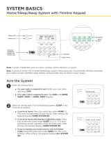
• Home/Sleep/Away — Your burglary protection is divided into
two or three areas: Perimeter, Interior, and Bedrooms.
Home (Perimeter) arming is for when you are staying inside but
want the comfort of knowing the exterior doors and windows
are armed.
Sleep (Perimeter and Interior) arms all areas except those near
bedrooms and nighttime areas.
Away (Perimeter, Interior, and Bedrooms) arms all three areas for
when you leave the building and no one is left inside.
Regardless of which mode is programmed, much of the operation
is similar. Throughout this guide, any differences between the
systems are noted for your convenience.

14 XT30/XT50 User Guide Arming and Disarming
exit delay tone at eight-second intervals until the last 10 seconds
when the keypad beeps at three-second intervals. After exiting the
building, if you re-enter during the countdown the exit countdown
restarts, allowing additional time to then disarm or again exit the
building during the countdown. This restart can occur only one
time. When the exit delay time ex pires, all disarmed zones are
armed. If your system uses a keyswitch to arm an area, the exit
delay time does NOT count down on the keypad display.
When you arm both the Perimeter and Interior to leave the building
but then you do not exit by the time the exit delay ends, the system
automatically arms but the interior area(s) will remain disarmed
because you have not exited.
Should you exit the building and the door does not close properly,
your system may be programmed so that when the exit delay
countdown ends, then the entry delay starts and the bell will sound
to alert you to the situation. Enter your user code to stop the bell
and disarm the system. Rearm the system, exit the building, and
make sure the door is securely closed.
ONE MOMENT . . . Message: If your system is monitored, it
may be programmed to wait for the arming report to be sent to
the monitoring station before displaying the armed mes sage. (See
Arming Report below.) This veries that the arming message was
received by your monitoring station. While the system waits, the
display reads ONE MOMENT.... If the report is received, the keypad
buzzes for one second and displays the armed message. If the
report is not received, the keypad displays LOCAL ALARM ONLY
before displaying the armed message.
Arming Report: Your system may be pre-programmed at installation
to send arming or zone bypass reports to a central station.
Key Fob Arming
Press the key fob button programmed for Arming or Toggle (Arm/
Disarm) button. A Red LED two-second acknowledgement indicates
All System On. A Green/Red two-second acknowledgement indicates
System On with some areas armed.
Key Fob Disarming
Press the key fob button programmed for Disarming or Toggle
(Arm/Disarm) button. A Green LED two-second acknowledgement
indicates All System Off.
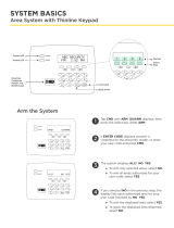
Area System Arming
Area Assignment: Your security system is programmed into separate
areas. The number of areas and their names are listed in the back
of this guide.
Arming or Disarming: You can arm and disarm all areas at one time
or each area individually. You can only arm or disarm areas authorized
for your user code.
All or Selective Arming: After entering your user code, the system
allows you to arm either all of the areas to which you have access
or one or more selected areas. If you choose to arm all areas, the
system begins verifying that all zones in those areas are in a good
condition. If you choose to arm selected areas, the system prompts
you to choose the areas you want to arm.
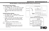
Arming the System
1. Press the CMD key until ARM DISARM displays.
2. Select ARM to turn on all protection.
3. Enter your user code if required. The display reads
ALL? NO YES.
4. Select NO to arm only selected areas. Go to step 5. Select
YES to arm all areas authorized for your user code.

Arming and Disarming XT30/XT50 User Guide 15
5. If NO is selected in step 4, the display begins to list each
area to which you have access followed by NO YES.
Example: OFFICE NO YES.
5a. Select YES for each area you want to arm.
5b. Select NO for each area you do NOT want to arm.
Note: You can also simply press the area numbers you want to arm
while ALL? NO YES displays. This changes the display to
AREAS:. The numbers you select appear in the display. For
example: AREAS: 2 4. Press CMD when done.
6. The system displays any faulted and bypassed zones in the
following order: faulted burglary zones, bypassed burglary
zones, faulted 24-hour zones, and bypassed 24-hour zones.
7. At this point you can force arm or bypass any faulted
burglary zones. A zone that is force armed is restored into the
system if it later returns to normal. A zone that is bypassed
remains bypassed until the system is disarmed. See steps 7a
through 7d.
7a.
If a problem exists on any zones, the zone name and
problem are shown followed by: OKAY BYPASS STOP.
7b. Select OKAY to force arm the zone(s) before arming.
7c. Select BYPASS to bypass the zone(s) before arming.
Note: 24-hour zones cannot be bypassed.
7d. Select STOP to stop the system from arming. Correct
the zone problem(s) and return to step 1.
8. The display reads SYSTEM ON if at least one area in the
system is armed, and ALL SYSTEM ON if all areas in the
system are armed.
9. The keypad then displays the exit time in seconds and
counts down the remaining time: EXIT: # # (# # = seconds
remaining). When the entire system is armed, the keypad
sounds the exit delay alert and when the delay expires, all
zones are armed.
Area System Disarming
Disarming: While the system is armed, you can only enter the premises
through an exit/entry delay door without causing an alarm. After
opening the door, the keypad sounds a prewarn tone to remind you
to disarm the system. You must disarm the system before the delay
time expires or an alarm on the door zone occurs.
During the prewarn tone, the keypad displays ENTER CODE: Enter
your user code to disarm the system. Only those areas authorized
for your user code disarm.
Note: Your system will silence the tone as soon as the rst user code
digit key is pressed. If a valid user code is not entered within
5 seconds or an invalid user code is entered, the prewarn tone
begins sounding again.
All or Selective Disarming: After entering your user code, the system
allows you to disarm either all of the areas to which you have access
or just selected areas. If you choose to disarm all areas, the system
automatically disarms them. If you choose to disarm selected areas,
the names of those areas display on the keypad.
Z-Wave Lock Disarming: If your system is installed with a Z-Wave
compatible lock, a valid user code entered at the lock will unlock
the door and disarm the areas to which you have access.
Alarm Display: After disarming, the keypad displays any zones that
went into alarm or any communication problems that occurred
during the armed period. All burglary zones are then disarmed and
any bypassed zones are automatically reset.
Disarmed Message: The keypad displays ALL SYSTEM OFF after the
system disarms.
Central Station Report: Your system may be pre-programmed at
installation to send a report of the disarming to the central station.

16 XT30/XT50 User Guide Arming and Disarming
Disarming During an Alarm
1. While the alarm bell or siren sounds, enter your user code
to silence the alarm. The keypad tone silences as soon as
the rst key is pressed.
For a burglary alarm, the keypad displays
IS THIS A FALSE ALARM? NO YES or CANCEL VERIFY.
This allows you to investigate the alarm prior to disarming
the system. This display remains on the keypad until a
selection is made, the Back Arrow is pressed, or the internal
system bell cutoff timer expires.
2. If a valid alarm has not occurred, select YES or CANCEL to
disarm the system and cancel the alarm.
The keypad next displays ALL SYSTEM OFF to conrm the
system is disarmed.
OR
If the alarm is valid, select NO or VERIFY to send a verify
message to the Central Station. The system will remain
armed.
All/Perimeter System Arming
Area Assignment: Your security system is divided into two separate
areas. Motion detectors, inside doors, and other interior protection
devices are assigned to the Interior area while windows and exterior
doors are assigned to the Perimeter area.
Perimeter or All: When arming an All/Perimeter system, the keypad
displays PERIM ALL. If you select ALL, you arm both the Perimeter
and the Interior of the system. You want to arm both of these areas
when leaving with nobody left inside. Selecting PERIM arms only
the Perimeter of the system. Perimeter arming is for when you are
staying inside but want the comfort of knowing the exterior doors
and windows are armed. Perimeter arming allows you to move freely
about inside without setting off any interior alarms.
Disarming an Area System
1. Press the CMD key until ARM DISARM displays. During entry
delay this process starts at step 3 below.
2. Select DISARM to disarm areas.
3. The keypad displays ENTER CODE: . Enter your user code
and press CMD. The keypad displays ALL? NO YES.
4. Select YES to disarm all areas authorized for your user code.
4a. Select NO to disarm only certain areas individually. The
keypad then displays the name of each area authorized for
your code followed by the NO YES display.
4b. Select YES to disarm the area displayed.
4c. Select NO to not disarm and to display the next area.
Note: You can also just press the area numbers you want to disarm
while at the ALL? NO YES display. This changes the display to
AREAS: . The area numbers you select appear in the display. For
example: AREAS: 2 4.
To remove an area number from the display, press its
corresponding number on the keypad. Press CMD when done.
5. After all areas have displayed, any alarms or communication
problems that occurred during the armed period are shown.
6. If all areas are disarmed, the keypad displays
ALL SYSTEM OFF.
/