Page is loading ...

Flat Screen Wall Mount | Tilt
TH-3065-LPT
Component Checklist
IMPORTANT INFORMATION
Step 1. Check Components
! IMPORTANT Install Telehook TH-3065-LPT Wall Mount as per the Installation Instructions
! This product supports a maximum load of 40Kg (88 lbs).
! This product only supports displays with mounting hole confi gurations from 100mm x 100mm (min.) to 600mm x 400mm (max.).
! The manufacturer does not accept responsibility for incorrect installation.
! Before installing this Telehook product, please check the display ventilation requirements with your LED/LCD manufacturer.
Check you have received all parts by comparing supplied parts against the Component Checklist and Hardware lists above.
Tilt Bracket (x2)
Wall Plate
Wall Plate
End Cap (x2)
A1
M4x12/25
(x4 each)
A2
M5x12/25
(x4 each)
A3
M6x12/25
(x4 each)
A4
M8x16/25
(x4 each)
A5
M8
Spacer
(x4 each)
A6
Multi
Washer
(x4 each)
B1
Coach
Screw
(x4 each)
B2
Nylon
Anchor
(x4 each)
B2
Washer
(x4 each)
Wall Mounting HardwareTools Required Display Mounting Hardware
• Power Drill
• Phillips Head
Screwdriver
• 5mm (
1
/
4
”) Drill Bit
• 10mm (
3
/
8
”)
Masonry Drill Bit
• 13mm (
1
/
2
”) Socket
Wrench or Shifter
Masonry Wall Timber Stud
5mm
(
3
/
16
”
)
50mm (2”)
Stud
10mm
(
3
/
8
”)
58mm
(2.3”)
Wall
OR
Tip: Use the supplied magnetic bubble level
to ensure wall plate is horizontal.
Note: Use a stud fi nder to accurately locate the centre of each
stud. Ensure that all four screws are fi xed securely into the studs.
B1
B1
10mm (
3
/
8
”) hole
5mm (
3
/
16
”) hole
B2
B3
B3
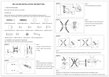
Step 2. Mount the Wall Plate
Installation Instructions

Click!
Push
Rear View of Screen
A
TOP
Pull
12
max
Step 3. Attach Tilt Brackets to Screen
Step 7. Cable Management
Step 6. Unlocking Screen
Step 8. Set Screen Tilt
Installation Complete
A5 Spacer (optional)
Use for recessed
mounting holes only.
Use longer mounting
screws with spacers.
Note: If dimension ‘A’ is larger than
195mm (7.68“) the maximum tilt
shown in Step 8 will be reduced.
A6 Multi-washer
Tilt Bracket
A1|A2|A3|A4
Mounting Screw
For M5 &
M6 Screws
For M4 Screws
For M8 Screws
Step 4. Attach End Caps
Step 5. Attach Screen to Wall Plate
(two people required)
Push each of the End Caps
onto the tabs at each end
of the wall plate.
5.1 Hook the Tilt
Brackets onto the
top edge of the
Wall Plate.
Unlock the Tilt
Brackets from
the wall plate.
Pull the bottom
of the screen out
from the wall to
provide access for
connecting cables
to the screen.
Once cables are
connected, lock
screen to Wall Plate
as in Step 5.2.
5.2 Lock the
screen to the
Wall Plate by
gently pushing
the bottom of
the screen.
Pull down both strings to unlock the Tilt
Brackets from the Wall Plate.
TIP: Hide strings by
sticking magnetic
pendants onto the
Tilt Brackets behind
the screen.
Once the brackets
are locked, set the
screen tilt by gently
pulling or pushing
the top edge of the
screen.
x2
No portion of this document or any artwork contained herein should be reproduced in any way without the express written consent of Atdec Pty Ltd.
Due to continuing product development, the manufacturer reserves the right to alter specifications without notice. Published 18.08.15 ©
/