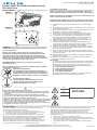
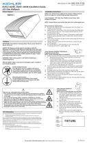
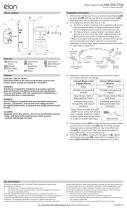
Kichler Lighting 16232AZT50 is an LED Wall Pack fixture designed for outdoor use. It is intended to be surface mounted on a wall in the lens down position. The fixture comes with a backplate that has a cast-in drill and knockout template to match any standard recessed junction box, three 5/16” knockouts for mounting holes and three 1/2” NPS tapped holes for surface conduit or photocontrol unit. The fixture is equipped with an LED driver that must be supplied with 120 to 277V, 50/60 Hz and connected to an individual, properly grounded branch circuit protected by a 20 Ampere circuit breaker.
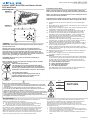
Kichler Lighting 16232AZT50 is an LED Wall Pack fixture designed for outdoor use. It is intended to be surface mounted on a wall in the lens down position. The fixture comes with a backplate that has a cast-in drill and knockout template to match any standard recessed junction box, three 5/16” knockouts for mounting holes and three 1/2” NPS tapped holes for surface conduit or photocontrol unit. The fixture is equipped with an LED driver that must be supplied with 120 to 277V, 50/60 Hz and connected to an individual, properly grounded branch circuit protected by a 20 Ampere circuit breaker.


-
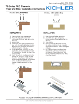
 1
1
-
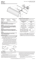
 2
2
-
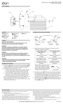
 3
3
-
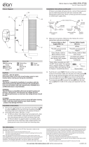
 4
4


Kichler Lighting 16232AZT50 User manual
- Type
- User manual
- This manual is also suitable for
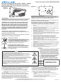
Kichler Lighting 16232AZT50 is an LED Wall Pack fixture designed for outdoor use. It is intended to be surface mounted on a wall in the lens down position. The fixture comes with a backplate that has a cast-in drill and knockout template to match any standard recessed junction box, three 5/16” knockouts for mounting holes and three 1/2” NPS tapped holes for surface conduit or photocontrol unit. The fixture is equipped with an LED driver that must be supplied with 120 to 277V, 50/60 Hz and connected to an individual, properly grounded branch circuit protected by a 20 Ampere circuit breaker.
Ask a question and I''ll find the answer in the document
Finding information in a document is now easier with AI
in other languages
Related papers
-
 Kichler Lighting 16236AZT30 User manual
-
Kichler Lighting 6UCSK30WHT User manual
-
 Kichler Lighting 8TD24V090BKT User manual
-
 Kichler Lighting 44248WHLED30 User manual
-
 Kichler Lighting 44249NILED30 User manual
-
 Kichler Lighting 1TEC1FLRC8SIL User manual
-
 Kichler Lighting 85049CH User manual
-
 Kichler Lighting 85054CH User manual
-
 Kichler Lighting 85081CH User manual
-
 Kichler Lighting 85068PN User manual


Other documents
-
Eurofase 23250-017 Installation guide
-
Wayfair Canada LED Flush Mount Light User manual
-
HOWARD LIGHTING MWP2 Installation guide
-
-
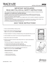 BARRON MRW Series Mini Polycarbonate Installation guide
-
Sunco Lighting LED Vapor Tight Jelly Jars User manual
-
-
GE FM Series Installation guide
-
Stonco Tall wall pack LED Install Instructions
