Page is loading ...

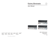
DXP Series Switchers
Serial Digital Video Matrix Switchers
68-595-01 Rev. C
09 07

This symbol is intended to alert the user of important operating and maintenance
(servicing) instructions in the literature provided with the equipment.
This symbol is intended to alert the user of the presence of uninsulated dangerous
voltage within the product’s enclosure that may present a risk of electric shock.
Caution
Read Instructions • Read and understand all safety and operating instructions before using the equipment.
Retain Instructions • The safety instructions should be kept for future reference.
Follow Warnings • Follow all warnings and instructions marked on the equipment or in the user
information.
Avoid Attachments • Do not use tools or attachments that are not recommended by the equipment
manufacturer because they may be hazardous.
Warning
Power sources • This equipment should be operated only from the power source indicated on the product. This
equipment is intended to be used with a main power system with a grounded (neutral) conductor. The
third (grounding) pin is a safety feature, do not attempt to bypass or disable it.
Power disconnection • To remove power from the equipment safely, remove all power cords from the rear of
the equipment, or the desktop power module (if detachable), or from the power source receptacle (wall
plug).
Power cord protection • Power cords should be routed so that they are not likely to be stepped on or pinched by
items placed upon or against them.
Servicing • Refer all servicing to qualifi ed service personnel. There are no user-serviceable parts inside. To
prevent the risk of shock, do not attempt to service this equipment yourself because opening or removing
covers may expose you to dangerous voltage or other hazards.
Slots and openings • If the equipment has slots or holes in the enclosure, these are provided to prevent
overheating of sensitive components inside. These openings must never be blocked by other objects.
Lithium battery • There is a danger of explosion if battery is incorrectly replaced. Replace it only with the
same or equivalent type recommended by the manufacturer. Dispose of used batteries according to the
manufacturer’s instructions.
Ce symbole sert à avertir l’utilisateur que la documentation fournie avec le matériel
contient des instructions importantes concernant l’exploitation et la maintenance
(réparation).
Ce symbole sert à avertir l’utilisateur de la présence dans le boîtier de l’appareil
de tensions dangereuses non isolées posant des risques d’électrocution.
Attention
Lire les instructions• Prendre connaissance de toutes les consignes de sécurité et d’exploitation avant
d’utiliser le matériel.
Conserver les instructions• Ranger les consignes de sécurité afi n de pouvoir les consulter à l’avenir.
Respecter les avertissements • Observer tous les avertissements et consignes marqués sur le matériel ou
présentés dans la documentation utilisateur.
Eviter les pièces de fi xation • Ne pas utiliser de pièces de fi xation ni d’outils non recommandés par le
fabricant du matériel car cela risquerait de poser certains dangers.
Avertissement
Alimentations• Ne faire fonctionner ce matériel qu’avec la source d’alimentation indiquée sur l’appareil. Ce
matériel doit être utilisé avec une alimentation principale comportant un fi l de terre (neutre). Le troisième
contact (de mise à la terre) constitue un dispositif de sécurité : n’essayez pas de la contourner ni de la
désactiver.
Déconnexion de l’alimentation• Pour mettre le matériel hors tension sans danger, déconnectez tous les cordons
d’alimentation de l’arrière de l’appareil ou du module d’alimentation de bureau (s’il est amovible) ou
encore de la prise secteur.
Protection du cordon d’alimentation • Acheminer les cordons d’alimentation de manière à ce que personne ne
risque de marcher dessus et à ce qu’ils ne soient pas écrasés ou pincés par des objets.
Réparation-maintenance • Faire exécuter toutes les interventions de réparation-maintenance par un technicien
qualifi é. Aucun des éléments internes ne peut être réparé par l’utilisateur. Afi n d’éviter tout danger
d’électrocution, l’utilisateur ne doit pas essayer de procéder lui-même à ces opérations car l’ouverture ou le
retrait des couvercles risquent de l’exposer à de hautes tensions et autres dangers.
Fentes et orifi ces • Si le boîtier de l’appareil comporte des fentes ou des orifi ces, ceux-ci servent à empêcher
les composants internes sensibles de surchauffer. Ces ouvertures ne doivent jamais être bloquées par des
objets.
Lithium Batterie • Il a danger d’explosion s’ll y a remplacment incorrect de la batterie. Remplacer uniquement
avec une batterie du meme type ou d’un ype equivalent recommande par le constructeur. Mettre au reut les
batteries usagees conformement aux instructions du fabricant.
Safety Instructions • English
Consignes de Sécurité • Français
Sicherheitsanleitungen • Deutsch
Dieses Symbol soll dem Benutzer in der im Lieferumfang enthaltenen
Dokumentation besonders wichtige Hinweise zur Bedienung und Wartung
(Instandhaltung) geben.
Dieses Symbol soll den Benutzer darauf aufmerksam machen, daß im Inneren des
Gehäuses dieses Produktes gefährliche Spannungen, die nicht isoliert sind und
die einen elektrischen Schock verursachen können, herrschen.
Achtung
Lesen der Anleitungen • Bevor Sie das Gerät zum ersten Mal verwenden, sollten Sie alle Sicherheits-und
Bedienungsanleitungen genau durchlesen und verstehen.
Aufbewahren der Anleitungen • Die Hinweise zur elektrischen Sicherheit des Produktes sollten Sie
aufbewahren, damit Sie im Bedarfsfall darauf zurückgreifen können.
Befolgen der Warnhinweise • Befolgen Sie alle Warnhinweise und Anleitungen auf dem Gerät oder in der
Benutzerdokumentation.
Keine Zusatzgeräte • Verwenden Sie keine Werkzeuge oder Zusatzgeräte, die nicht ausdrücklich vom
Hersteller empfohlen wurden, da diese eine Gefahrenquelle darstellen können.
Vorsicht
Stromquellen • Dieses Gerät sollte nur über die auf dem Produkt angegebene Stromquelle betrieben werden.
Dieses Gerät wurde für eine Verwendung mit einer Hauptstromleitung mit einem geerdeten (neutralen)
Leiter konzipiert. Der dritte Kontakt ist für einen Erdanschluß, und stellt eine Sicherheitsfunktion dar. Diese
sollte nicht umgangen oder außer Betrieb gesetzt werden.
Stromunterbrechung • Um das Gerät auf sichere Weise vom Netz zu trennen, sollten Sie alle Netzkabel
aus der Rückseite des Gerätes, aus der externen Stomversorgung (falls dies möglich ist) oder aus der
Wandsteckdose ziehen.
Schutz des Netzkabels • Netzkabel sollten stets so verlegt werden, daß sie nicht im Weg liegen und niemand
darauf treten kann oder Objekte darauf- oder unmittelbar dagegengestellt werden können.
Wartung • Alle Wartungsmaßnahmen sollten nur von qualifi ziertem Servicepersonal durchgeführt werden.
Die internen Komponenten des Gerätes sind wartungsfrei. Zur Vermeidung eines elektrischen Schocks
versuchen Sie in keinem Fall, dieses Gerät selbst öffnen, da beim Entfernen der Abdeckungen die Gefahr
eines elektrischen Schlags und/oder andere Gefahren bestehen.
Schlitze und Öffnungen • Wenn das Gerät Schlitze oder Löcher im Gehäuse aufweist, dienen diese zur
Vermeidung einer Überhitzung der empfi ndlichen Teile im Inneren. Diese Öffnungen dürfen niemals von
anderen Objekten blockiert werden.
Litium-Batterie • Explosionsgefahr, falls die Batterie nicht richtig ersetzt wird. Ersetzen Sie verbrauchte
Batterien nur durch den gleichen oder einen vergleichbaren Batterietyp, der auch vom Hersteller
empfohlen wird. Entsorgen Sie verbrauchte Batterien bitte gemäß den Herstelleranweisungen.
Este símbolo se utiliza para advertir al usuario sobre instrucciones importantes
de operación y mantenimiento (o cambio de partes) que se desean destacar en el
contenido de la documentación suministrada con los equipos.
Este símbolo se utiliza para advertir al usuario sobre la presencia de elementos con
voltaje peligroso sin protección aislante, que puedan encontrarse dentro de la caja
o alojamiento del producto, y que puedan representar riesgo de electrocución.
Precaucion
Leer las instrucciones • Leer y analizar todas las instrucciones de operación y seguridad, antes de usar el
equipo.
Conservar las instrucciones • Conservar las instrucciones de seguridad para futura consulta.
Obedecer las advertencias • Todas las advertencias e instrucciones marcadas en el equipo o en la
documentación del usuario, deben ser obedecidas.
Evitar el uso de accesorios • No usar herramientas o accesorios que no sean especifi camente recomendados
por el fabricante, ya que podrian implicar riesgos.
Advertencia
Alimentación eléctrica • Este equipo debe conectarse únicamente a la fuente/tipo de alimentación eléctrica
indicada en el mismo. La alimentación eléctrica de este equipo debe provenir de un sistema de distribución
general con conductor neutro a tierra. La tercera pata (puesta a tierra) es una medida de seguridad, no
puentearia ni eliminaria.
Desconexión de alimentación eléctrica • Para desconectar con seguridad la acometida de alimentación eléctrica
al equipo, desenchufar todos los cables de alimentación en el panel trasero del equipo, o desenchufar el
módulo de alimentación (si fuera independiente), o desenchufar el cable del receptáculo de la pared.
Protección del cables de alimentación • Los cables de alimentación eléctrica se deben instalar en lugares donde
no sean pisados ni apretados por objetos que se puedan apoyar sobre ellos.
Reparaciones/mantenimiento • Solicitar siempre los servicios técnicos de personal califi cado. En el interior no
hay partes a las que el usuario deba acceder. Para evitar riesgo de electrocución, no intentar personalmente
la reparación/mantenimiento de este equipo, ya que al abrir o extraer las tapas puede quedar expuesto a
voltajes peligrosos u otros riesgos.
Ranuras y aberturas • Si el equipo posee ranuras o orifi cios en su caja/alojamiento, es para evitar el
sobrecalientamiento de componentes internos sensibles. Estas aberturas nunca se deben obstruir con otros
objetos.
Batería de litio • Existe riesgo de explosión si esta batería se coloca en la posición incorrecta. Cambiar esta
batería únicamente con el mismo tipo (o su equivalente) recomendado por el fabricante. Desachar las
baterías usadas siguiendo las instrucciones del fabricante.
Instrucciones de seguridad • Español
Precautions
ᅝܼ乏ⶹ•Ё᭛
䖭Ͼヺোᦤ⼎⫼᠋䆹䆒⫼᠋ݠЁ᳝䞡㽕ⱘ᪡㓈ᡸ䇈ᯢDŽ
䖭Ͼヺো䄺ਞ⫼᠋䆹䆒ᴎݙ᳝ᲈ䴆ⱘॅ䰽⬉य़ˈ᳝㾺⬉ॅ䰽DŽ
⊼ᛣ
䯙䇏䇈ᯢк• 䑩ㅸỀ䑩嬦嫿⡈⼆枼敆嬼䍇夤ㆁ㙊⫊₩⏍Ề䑩嬵㕏ɿ
ֱᄬ䇈ᯢк• 䑩ㅸⷕ⪙⫊₩嬵㕏ᶧḦ⡈⭇㚦Ề䑩ɿ
䙉ᅜ䄺ਞ• 䑩ㅸⷕ徶⫉ᷨ␂⏍䑩ㅸ㉈⊘ᵋ䗅ㆁ㙊⫊₩⏍㐎ẝ嬵㕏ɿ
䙓ܡ䗑ࡴ• ᵎ壂Ề䑩嬦ᷨ␂⋃⒇㯢㙊㋩劑䗅₸ㅗ弾⇡嫿⡈澤Ḧ忀₎⊲斪ɿ
䄺ਞ
⬉⑤• 嬦嫿⡈⌫倾Ề䑩ᷨ␂ᵋ㝈㕏䗅䑶㷑ɿ嫿⡈⼆枼Ề䑩㙊♱一䗅Ờ䑶䰼丠Ờ䑶ɿ䩭ᵊ㚢一
澠♱一澡㕰⫊₩嫿㓾澤ᵎ倾ᵎ䑩ㅗ崴弈ɿ
ᢨᥝ⬉⑤• ᵻ⫊₩♱ḏ嫿⡈㈕㋊䑶㷑澤嬸㈕㋊ㆁ㙊嫿⡈⍏ㅗ㞍暣䑶㷑䗅䑶㷑一澤ㅗḼẖ㋦ⅱⵃ
䑶䰼丠䗅䑶㷑一ɿ
⬉⑤㒓ֱᡸ• ⣦Ⓟⵄ一澤忀₎埬嵪嵐澤ㅗ愎䆪㉥⋌ɿ
㓈ᡸ•ㆁ㙊丵Ἧ⼆枼䑲嫥嬂䗅丵Ἧ᷻⎙弜垍ɿ嫿⡈怩㯢㙊䑩ㅸ⌰Ḧ㘵㊣䗅昷ḷɿᵻ忀₎℻
䋱大䑶⊲斪ᵎ壂儫ⴲ嬖☿㆔⹁嫿⡈䘗⪑丵Ἧ嬦嫿⡈ɿ
䗮亢ᄨ• 㙊ᷜ嫿⡈㙻⠴ᵋ㙊彛栏㤾ㅗ⪕澤⫄ḭ㕰䑩㚦敳㪣㙻㒐だ₄ḷ弈䀮ɿᵎ壂䑩Ḽẖᵝ
壀㉢Ẑ彛栏⪕ɿ
䫖⬉∴• ᵎ㪤䞯䗅㘵㊣䑶㮡ṛ㙊䅇㿹䗅⊲斪ɿ⼆枼Ề䑩ᵏ⋃⫷㋩劑䗅䘹⍍ㅗ䘹弒⛌⌸䗅䑶㮡ɿ
㉊䂨䑠ᷨ⋃䗅⸻嫯⡅䍇ⷠ⹄䑶㮡ɿ

FCC Class A Notice
N
This equipment has been tested and found to comply with the limits for a
Class A digital device, pursuant to part 15 of the FCC Rules. These limits are
designed to provide reasonable protection against harmful interference when
the equipment is operated in a commercial environment. This equipment
generates, uses and can radiate radio frequency energy and, if not installed
and used in accordance with the instruction manual, may cause harmful
interference to radio communications. Operation of this equipment in a
residential area is likely to cause harmful interference, in which case the
user will be required to correct the interference at his own expense.
N
This unit was tested with shielded cables on the peripheral devices. Shielded
cables must be used with the unit to ensure compliance.
This device complies with Part 15 of the FCC Rules. Operation is subject
to the following two conditions: (1) this device may not cause harmful
interference, and (2) this device must accept any interference received,
including interference that may cause undesired operation

QS-1Digital XPoint Matrix Switchers • Quick Start
Quick Start — Digital XPoint Matrix Switchers
Installation
Step 1
Turn off power to the input and output devices,
and remove the power cords from them.
Step 2
Mount the switcher in a rack or under a table.
Step 3
Connect:
a Up to 4 or 8 SDI inputs to the Input In (top)
connectors.
b Up to 4 or 8 SDI displays or other devices to
the Input loop-through (bottom) connectors.
c Up to 8 or 16 SDI display or other devices to
the Output connectors.
Each output number consists of two
identical SDI outputs.
Step 4
If desired, connect a control system or computer to
the RS-232/RS-422 port.
Step 5
If desired, attach an external sync timing device to
the external sync connectors.
Step 6
Plug the switcher, input devices, and output
devices into a grounded AC source, and turn on the
input and output devices.
Definitions
The following terms are used throughout this
manual:
Tie — An input-to-output connection.
Set of ties — An input tied to two or more outputs.
(An output can never be tied to multiple
inputs.)
Configuration — One or more ties or sets of ties.
Current configuration — The currently active
configuration (also called configuration 0).
Preset — A configuration that has been stored. One
preset can be assigned to each input and output
button. Additional presets are available under
RS-232/422 control. When a preset is retrieved, it
becomes the current configuration.
Front Panel Controls
Input and output buttons select and identify
inputs and outputs. The buttons also select
presets.
Enter button saves changes when you change the
configuration.
Preset button saves a configuration as a preset or
recalls a previously-defined preset.
Input and output buttons can hold text or icon
inserts that can be created easily with Extron’s
label software.
LCD Displays
To view the current configuration, press and release
the button for the desired input. The LCD displays
the input number for approximately 1 second and
then the current configuration for approximately
10 seconds. The LCD displays each output number
on the top line and the tied inputs on the bottom
line. To check the status of another source, press
and release another Input button.
STATUS
1
Second
STATUS STATUS
DXP 88
EXTRON
10
Seconds
Input #5
_
555
____
12345678
1
SDI
S
ource
SDI
Loop-throug
h
3a
3b
1
SDI
Destinatio
n
SDI
Destinatio
n
3c
Female
51
96
Male
15
69
RS-232 FunctionPin
1
2
3
4
5
6
7
8
9
—
TX
RX
—
Gnd
—
—
—
—
Not used
Transmit data
Receive data
Not used
Signal ground
Not used
Not used
Not used
Not used
RS-422 Function
TX-
TX+
RX+
RX-
Gnd
—
—
—
—
Transmit data (-
)
Transmit data (+
)
Receive data (+)
Receive data (-)
Signal ground
Not used
Not used
Not used
Not used
4

Quick Start — Digital XPoint Matrix Switchers, cont’d
Digital XPoint Matrix Switchers • Quick StartQS-2
Quick Start button key
Toggle switch modes
The switch mode is for ties only and has no
effect on saving and recalling presets.
Toggle between the two switch modes, enter and
quick switch, by pressing and holding the Enter
button for approximately 2 seconds.
In enter switch mode, changes do not take effect
until you press Enter. In quick switch mode,
changes take place as you select them, without
pressing Enter.
To check the current switch mode, press and release
an output button. In enter switch mode, output
buttons light green when selected. In quick switch
mode, the output buttons light red.
Create a tie in enter switch mode
1. Press and release the desired input button.
2. Press and release the desired output button(s).
3. Press and release the Enter button.
P
ress and
h
old for 2
seconds.
ENTER
Mode
Ent er
DXP 88
EXTRON
Swi t ch
Qu i ck
— or —
8 Second Timeout
5
INPUTS
OUTPUTS
I n p u t # 5
_ _ _ _ _ _ _ _
1 2 3 4 5 6 7 8
Press the input button.
The button lights green.
1 Second
Press the output buttons.
The buttons blink green.
The Enter button
blinks green.
3 4 8
ENTER
Save a preset
1. Press and hold the Preset button until the
button begins to blink.
2. Press and release the input or output button
associated with the desired preset number.
DXP 88 SDI: The buttons select preset 1
through 16, in order.
DXP 44 SDI: The buttons select preset 1
through 8, in order.
3. Press and release the Enter button.
Viewing or recalling a preset
1. (DXP 44 SDI shown.) Press and release the
Preset button.
2. Press and release the input or output button
associated with the desired preset number.
3. To recall the preset, press and release the Enter
button.
Preset
Save
123 56478
Press and hold the Preset button until it blinks.
O
utputs displayed until the DXP enters save preset mode
.
2 Seconds
PRESET PRESET
= Blinking button
Press and release an input or output button.
The button lights red.
The Enter button
blinks red.
1 4
ENTER
INPUT
— THRU —
1
INPUT
Preset 1
OUTPUT
— THRU —
DXP 88 SDI
DXP 44 SDI
Preset 1
Preset 16
Preset 8
OUTPUT
8
1234
The LCD display
s
the outputs
.
PRESET
INPUTS
OUTPUTS
P
ress the
P
reset button.
The LCD shows the
tie's configuration.
__
55
123
Press and release an input or output button.
The button lights red.
The Enter
button blinks
red.
1 4
__
55
___
5
123 56478
ENTER
INPUT
— THRU —
1
INPUT
Preset 1
OUTPUT
— THRU —
DXP 88 SDI
DXP 44 SDI
Preset 1
Preset 16
Preset 8
OUTPUT
8

i
Digital XPoint Matrix Switchers • Table of Contents
Table of Contents
Chapter 1 • Introduction ....................................................................................................... 1-1
About the Digital XPoint Series Matrix Switchers ............................................ 1-2
Features ................................................................................................................................... 1-3
Chapter 2 • Installation .......................................................................................................... 2-1
Mounting the Switcher .................................................................................................... 2-2
Table or wall mounting ..................................................................................................... 2-2
Rack mounting ................................................................................................................... 2-2
UL requirements .................................................................................................................. 2-2
Mounting instructions ........................................................................................................ 2-3
Cabling and Rear Panel Views...................................................................................... 2-4
Digital video input and output connections .................................................................... 2-4
RS-232/422 connection ...................................................................................................... 2-5
External sync connection ................................................................................................... 2-5
Power connection .............................................................................................................. 2-6
Chapter 3 • Operation ............................................................................................................. 3-1
Front Panel Controls and Indicators ......................................................................... 3-2
Definitions .......................................................................................................................... 3-2
LCD display ......................................................................................................................... 3-2
Input buttons and output buttons ................................................................................... 3-2
Control buttons.................................................................................................................. 3-3
Button icons ....................................................................................................................... 3-3
Front Panel Operations .................................................................................................... 3-3
Power ................................................................................................................................. 3-3
Switch modes ..................................................................................................................... 3-4
Creating a configuration ................................................................................................... 3-4
Example 1a: Create a set of ties in enter switch mode ................................................... 3-5
Example 1b: Create a set of ties in quick switch mode ................................................... 3-6
Example 2: Add a tie to a set of ties ................................................................................. 3-7
Example 3: Remove a tie from a set of ties ...................................................................... 3-8
Viewing the current configuration ................................................................................... 3-9
Using presets ...................................................................................................................... 3-9
Example 4: Save a preset ................................................................................................. 3-10
Example 5: View or recall a preset .................................................................................. 3-10
Background illumination ................................................................................................. 3-12
Executive mode (front panel security lockout) .............................................................. 3-12
System reset to factory defaults ..................................................................................... 3-12
Worksheets .......................................................................................................................... 3-13
Worksheet example 1: Entering system equipment ..................................................... 3-13
Worksheet example 2: Drawing ties .............................................................................. 3-14
Worksheet example 3: Test configuration ..................................................................... 3-15
Configuration worksheet ................................................................................................ 3-17

ii Digital XPoint Matrix Switchers • Table of Contents
Table of Contents, cont’d
Chapter 4 • Programmer’s Guide ..................................................................................... 4-1
Host-to-Switcher Instructions....................................................................................... 4-2
Switcher-Initiated Messages ......................................................................................... 4-2
Switcher Error Responses ............................................................................................... 4-3
Using the Command/Response Table ........................................................................ 4-3
Command/Response Table for SIS Commands ..................................................... 4-4
Symbol definitions ............................................................................................................. 4-4
Chapter 5 • Matrix Software .............................................................................................. 5-1
Matrix Switchers Control Program ............................................................................ 5-2
Installing the software ...................................................................................................... 5-2
Using the software ............................................................................................................ 5-3
Windows buttons, drop boxes, and trash ..................................................................... 5-5
Windows menus ........................................................................................................... 5-5
Using emulation mode ................................................................................................. 5-8
Using the help system ................................................................................................... 5-8
Button Label Generator Software .............................................................................. 5-8
Using the software ............................................................................................................ 5-9
Chapter 6 • Maintenance and Modifications .......................................................... 6-1
Hardware Upgrades and Maintenance ..................................................................... 6-2
Opening the switcher ........................................................................................................ 6-2
Closing the switcher .......................................................................................................... 6-2
Swapping the serial ports .................................................................................................. 6-3
Installing a firmware update ............................................................................................ 6-4
Replacing the AC fuse ....................................................................................................... 6-5
Creating and Installing Button Labels ..................................................................... 6-6
Appendix A • Reference Information .......................................................................... A-1
Specifications....................................................................................................................... A-2
Part Numbers ....................................................................................................................... A-4
Digital XPoint part numbers ............................................................................................ A-4
Replacement parts ............................................................................................................ A-4
Optional accessories ......................................................................................................... A-4
Cables ................................................................................................................................ A-4
68-595-01 Rev. C
09 07
All trademarks mentioned in this manual are the properties of their respective owners.

Digital XPoint Matrix Switchers
1
Chapter One
Introduction
About the Digital XPoint Series Matrix Switchers
Features

Introduction, cont’d
Digital XPoint Matrix Switchers • Introduction1-2
Introduction
About the Digital XPoint Series Matrix Switchers
The Extron Digital XPoint Series Matrix Switchers are serial digital interface (SDI)
matrix switchers that distribute any SDI input to any combination of SDI outputs.
The matrix switchers can route multiple input/output configurations
simultaneously. Two matrix sizes are available:
• DXP 44 SDI (four inputs by four outputs)
• DXP 88 SDI (eight inputs by eight outputs)
The switchers conform to the SMPTE 259M specifications and route signals in all
composite (143 Mb/s and 177 Mb/s), component 4:2:2 (270 Mb/s), and widescreen
16:9 (360 Mb/s) SDI video standards. Each input signal is equalized: a 270 Mb/s
input signal is equalized for distances of 1000 feet (300 meters) on high quality
cable such as Extron RG6 BNC Series Super High Resolution coaxial cable. Each
input signal is buffered and looped through to allow it to be sent to other
equipment. Each output has dual buffered and equalized BNC outputs (two
identical output signals per output) (figure 1-1).
1.5A MAX
100-240V 50-60Hz
INPUTS
1
2 3 4
5
6
7
8
OUTPUTS
1
2
3
4
5 6
7
8
EXT.
REF.
IN
RS232/422
OUT
Camera
1
P
review
1
Camera
2
Preview
2
Character/
Logo Generator
D-VTR
VSC 300D
Video Scan Converter
Digital Video
Editing Station
Program
Preview
Vectorscope
External Syn
c
Reference
Serial
Communications
Media Serve
rs
PROGRAM
OUT
RS-232
RS-422
DXP 88 SDI
0
10
20
30
40
50
60
70
80
90
100
110
120
130
140
150
160
170
180
190
200
210
220
230
240
250
260
270
280
290
300
310
320
330
340
350
Figure 1-1 — Typical Digital XPoint Switcher application
The switcher has an RS-232/422 port for local control. The switcher can be
controlled via the front panel or using the Extron Simple Instruction Set™ (SIS™)
and/or Extron’s Windows-based control program via the RS-232/422 link.
The Digital XPoint Series Matrix Switchers are housed in rack-mountable, 1U high,
17.5" (44.5 cm) wide metal enclosures. With the included mounting brackets, the
switchers can be rack mounted, mounted under a desk or table, or mounted against
a wall or the side of a desk. Each model has an internal 100VAC to 240VAC, 50/60
Hz, 40 watt power supply that provides worldwide power compatibility.

1-3Digital XPoint Matrix Switchers • Introduction
Features
Inputs — 4 or 8 SDI video inputs on BNC connectors and 4 or 8 equalized and
buffered loop-throughs on BNC connectors
Outputs — 4 or 8 SDI video outputs with two buffered and equalized outputs each
on BNC connectors
Serial digital data rates from 143 Mb/s to 360 Mb/s — Capable of switching signals
in 4fsc (composite) or 4:2:2 (component) serial digital video transmission
standards
Society of Motion Picture and Television Engineers (SMPTE) 259M SDI standard
compliance
Automatic input cable equalization — Each input signal is equalized: a 270 Mb/s
input signal is equalized for distances of 1000 feet (305 meters) on high
quality cable such as Extron SuperFlex SHR Super High Resolution coaxial
cable.
Automatic rate selection — The Digital XPoint automatically accepts four SMPTE
data rates, including 143 Mb/s, 177 Mb/s, 270 Mb/s, and 360 Mb/s. The
auto rate selection is ideal for multi-rate serial data protocols because the
switcher automatically detects and locks onto the incoming data signal.
Output data muting when the input source is lost — An internal muting function
forces the serial data outputs to a static state when input data is not present
or not locked.
16 global memory presets — 16 memory presets are a time-saving feature that lets
you set up and store input/output configurations in advance and then recall
those configurations with a few simple steps when needed.
Operational flexibility — Operations such as input/output selection and setting of
presets can be performed on the front panel or over the RS-232/RS-422 link.
The RS-232/RS-422 link allows remote control via a PC or control system.
• Front Panel Controller — The Digital XPoint Series front panel controller
supports touch-of-a-button input and output selection and preset creation
and selection. The front panel features large, positive touch, illuminated
pushbuttons that can be labeled with text or graphics.
• Windows-based control program — Extron’s Windows-based control
program provides a versatile range of operational options with its graphical
interface and drag-and-drop/point-and-click operation. The Windows-based
control program also has an emulation mode that lets you create a switcher
configuration file at the home office and then download it for use by the
switcher on site.
• Simple Instruction Set (SIS) — The remote control protocol uses Extron’s SIS
for easy programming and operation.
Input carrier detection — When input data is locked, the DXP indicates the
presence of a carrier source. This information is available via the
RS-232/RS-422 port and either the Windows-based control program or an SIS
command.
Remote control — The Digital XPoint switchers are remote controllable, using the
MKP 1000 master control keypad and any combination of MCP 1000 slave
control panels and/or MKP 1000 slave control keypads. The remote control
devices are easy to use and provide tactile buttons for quick selection. Each
MCP 1000 can be used for one-touch switching for a particular output and for
selecting global presets. Each MKP 1000 dedicated to an output can be used
to select a different input for that output or to select a preset.

Introduction, cont’d
Digital XPoint Matrix Switchers • Introduction1-4
LCD display — The LCD displays the I/O configuration, preset configurations,
and the status of additional system features.
Mounting flexibility — Mounting brackets make the 1U high switchers mountable
in any conventional 19" (48 cm) wide rack, or under or through a desk or
other furniture.
Power supply — The 100 VAC to 240 VAC, internal power supply of the
Digital XPoint Series provides worldwide power compatibility.

Digital XPoint Matrix Switchers
2
Chapter Two
Installation
Mounting the Switcher
Cabling and Rear Panel Views

Installation, cont’d
Digital XPoint Matrix Switchers • Installation2-2
Installation
Mounting the Switcher
The Digital XPoint Matrix Switcher comes with two sets of mounting brackets. One
set is for mounting the switcher under a table or against a wall, and the other set is
for rack mounting.
Table or wall mounting
The table/wall mounting brackets extend approximately 1/4” (6.4 mm) above the
top surface of the switcher enclosure. This design allows for an air space between
the enclosure and the surface to which it is mounted. Table or wall mount the
switcher as follows:
1. Attach the table/wall mounting brackets to the switcher with the eight
provided #8 machine screws (figure 2-1).
2. Hold the switcher with the attached brackets against the underside of the
table or other furniture, or against the wall. Mark the location of the
screw holes of the bracket on the mounting surface.
3. Drill 3/32” (2 mm) diameter pilot holes, 1/4” (6.4 mm) deep in the
mounting surface at the marked screw locations.
4. Insert #8 wood screws into the four pilot holes. Tighten each screw into
the mounting surface until just less than 1/4” of the screw protrudes.
5. Align the mounting screws with the slots in the brackets and place the
switcher against the surface, with the screws through the bracket slots.
6. Slide the switcher slightly forward or back, then tighten all four screws to
secure the switcher in place.
Rack mounting
UL requirements
The following Underwriters Laboratories (UL) requirements pertain to the
installation of the matrix switcher into a rack (figure 2-1).
1. Elevated operating ambient temperature — If installed in a closed or multi-
unit rack assembly, the operating ambient temperature of the rack
environment may be greater than room ambient. Therefore, consider
installing the equipment in an environment compatible with the maximum
ambient temperature (Tma) specified by the manufacturer.
2. Reduced air flow — Installation of the equipment in a rack should be such
that the amount of air flow required for safe operation of the equipment is not
compromised.
3.
Mechanical loading — Mounting of the equipment in the rack should be such
that a hazardous condition is not achieved due to uneven mechanical loading.
4. Circuit overloading — Consideration should be given to the connection of the
equipment to the supply circuit and the effect that overloading of the circuits
might have on overcurrent protection and supply wiring. Appropriate
consideration of equipment nameplate ratings should be used when
addressing this concern.
5. Reliable earthing (grounding) — Reliable earthing of rack-mounted
equipment should be maintained. Particular attention should be given to
supply connections other than direct connections to the branch circuit (e.g.
use of power strips.

2-3Digital XPoint Matrix Switchers • Installation
Mounting instructions
Rack mount the switcher as follows:
1. Attach the rack mounting brackets to the switcher with the eight
provided #8 machine screws (figure 2-1).
1.5A MAX
100-240V 50-60Hz
INPUTS
1 2
3
4 5 6 7 8
OUTPUTS
1 2 3 4
5 6
7 8
EXT. REF.
IN
RS232/422
OUT
#
8 Screw (4 Places)
E
ach Side
Mounting Screws (2 Plcs)
Each Side
or
Rack-mounting
Bracket
Table/
Wall-mounting
Bracket
Drill pilot holes —
3/32” (2.4 mm) di
a.
1/4” (6.4 mm) dee
p
Figure 2-1 — Mounting the Digital XPoint Switcher
2. Insert the switcher into the rack, aligning the holes in the mounting
bracket with those of the rack.
3. Secure the switcher to the rack using the supplied machine screws.

Installation, cont’d
Digital XPoint Matrix Switchers • Installation2-4
Cabling and Rear Panel Views
All connectors are on the rear panel. Figure 2-2 shows the rear of the
Digital XPoint 88 Matrix Switcher. The Digital XPoint 44 is housed in the same 1U
enclosure, but has fewer input and output connectors to accommodate the different
matrix size that it provides. Figure 2-3 shows the Digital XPoint 44 Matrix
Switcher.
1.5A MAX
100-240V 50-60Hz
INPUTS
1 2 3 4 5 6 7 8
OUTPUTS
1 2 3 4 5 6 7 8
EXT. REF.
IN
RS232/422
OUT
1
2
3
5
4
6
Figure 2-2 — Rear panel connectors, DXP 88 SDI
1.5A MAX
100-240V 50-60Hz
INPUTS
1 2 3 4
OUTPUTS
1 2 3 4
EXT. REF.
IN
RS232/422
OUT
1
2
3
5
4
6
Figure 2-3 — Rear panel connectors, DXP 44 SDI
Digital video input and output connections
All video input and output connections to the Digital XPoint Switchers are
made with female BNC connectors. Some types of video output devices do not
have BNC video output connectors. For these cases, a suitable cable or
connector adapter is necessary between the device output connector and the
BNC input connector of the Digital XPoint.
1
Input in (top) video connectors — Connect an SDI input device to these
female BNC connectors.
2
Input loop-through (bottom) video connectors — Connect an SDI display or
other device to these female BNC connectors. The switcher outputs an
equalized SDI loop-though on these BNCs.
The Digital XPoint Matrix Switchers equalize the output signals and the loop-
through signals. Beyond that, they do not alter the video signal in any way.
The signal output by the switcher is in the same format as the input.
3
Output video connectors — Connect an SDI display or other device to these
female BNC connectors. The switcher outputs two identical, equalized SDI
signals for each output number.

2-5Digital XPoint Matrix Switchers • Installation
RS-232/422 connection
4
RS-232/RS-422 port — If desired, connect a host device, such as a computer or
touch panel control, to the Digital XPoint via this 9-pin D connector for serial
RS-232/RS-422 control (figure 2-4).
Female
51
96
Male
15
69
RS-232 FunctionPin
1
2
3
4
5
6
7
8
9
—
TX
RX
—
Gnd
—
—
—
—
Not used
Transmit data
Receive data
Not used
Signal ground
Not used
Not used
Not used
Not used
RS-422 Function
TX-
TX+
RX+
RX-
Gnd
—
—
—
—
Transmit data (-
)
Transmit data (+
)
Receive data (+)
Receive data (-)
Signal ground
Not used
Not used
Not used
Not used
Figure 2-4 — RS-232/RS-422 port pin assignments
See chapter 4, “Programmer’s Guide”, for definitions of the SIS commands
and chapter 5, “Matrix Software”, to install and use the control software.
The Digital XPoint Series Matrix Switchers are factory configured for RS-232
control. To use the switcher under RS-422 control, an internal cable must be
moved. See chapter 6, “Maintenance and Modifications”, for the procedure for
swapping the serial ports.
If desired, connect an MCP 1000 remote control panel master unit to the
switcher’s RS-232/RS-422 connector. You can also connect an MKP 1000
remote keypad or MCP 1000 slave unit to the MCP 1000 master unit. Refer to
the MCP 1000 Remote Control Panel User’s Manual, part #68-456-01, and the
MKP 1000 User’s Manual, part #68-355-01, for details.
External sync connection
When switching between inputs, the resulting image change should be seamless, or
clean. The Digital XPoint Switchers can use an external signal to synchronize
switching during the vertical sync interval. Without the external sync locking
feature, switching between inputs can result in a brief rolling (sync loss) or a brief
change in the picture size.
5
External Reference In (top) connector — Connect an external sync signal to
this BNC connection for genlocking the video signal in broadcast or other
sync-critical applications.
External Reference Out (bottom) connector — Connect any downstream
equipment that requires genlocking to this BNC connector to route the
external sync signal throughout the system in broadcast or other sync-critical
applications.
Figure 2-5 shows a basic external sync configuration. The External Reference In
connector receives a timing signal. The External Reference Out connector allows
the signal to be passed on to another video device, if required.
Rear Panel
To Next Devic
e
or Terminate
POWER
12V
.2A MAX
LR
4
3
2
1
6
5
PAL
NTSC
BLACKBURST
BLACKBURST
COLORBARS
-10
+4
1 2 3
ON
1 KHZ
AUDI O
BBG 6 A
BLACKBURST AND AUDIO
GENERATOR
Extron
BBG 6 A
Blackburst/
Audio Generator
8
EXT. REF.
IN
RS232/422
OUT
IN
Figure 2-5 —Simple external sync connection example

Installation, cont’d
Digital XPoint Matrix Switchers • Installation2-6
Figure 2-6 shows a configuration in which the timing signal passes through three
video cameras before connecting to the switcher. This type of video camera is
capable of synchronizing with the external timing source for video editing
applications.
If no external sync timing source is connected to the switcher, switching occurs
immediately rather than during the next vertical sync interval.
.3A MAX
100-240V 5
0-60Hz
INPUTS
1
IN
OUT
2
IN
OUT
3
IN
OUT
4
IN
OUT
5
IN
OUT
6
IN
OUT
7
IN
OUT
8
IN
OUT
OUTPUTS
123
4 5
6
7
8
EXT. REF.
IN
RS232/422
OUT
POW
ER
12V
.2A MAX
L R
4
3
2
1
6
5
PAL
NTSC
BLACKBURST
BLACKBUR
ST
COLORB
ARS
-10
+4
1
2 3
ON
1 K
HZ
AUD
IO
BBG 6
A
BLACKB
URST AN
D AUDI
O
GEN
ERA
TOR
Extron
BBG 6 A
Blackburst/
Audio Generator
Video Camera Video Camera Video Camera
Monitor Monitor
VCR
DXP 88 SDI
SDI-AVR 100
SOG
RGB/YUV
SET UP
BETA
COLOR BARS
NTSC/PAL
100-240V 50/
60 Hz 0.2A
SDI INPUT
OUTPUTS
IN
OUT
COMPOSITE
OUTPUT
S-VIDEO
OUTPUT
R/R-Y G/Y
B/B-Y
H
V
S
ON
OFF
VCR
Figure 2-6 — Multiple device external sync connection example
Power connection
6
AC power connector — Plug a standard IEC power cord into this connector
to connect the switcher to a 100 to 240 VAC, 50 Hz or 60 Hz power source.

Digital XPoint Matrix Switchers
3
Chapter Three
Operation
Front Panel Controls and Indicators
Front Panel Operations
Worksheets

Operation, cont’d
Digital XPoint Matrix Switchers • Operation3-2
Operation
Front Panel Controls and Indicators
All Digital XPoint controls and indicators are on the front panel (figure 3-1). The
large, illuminated push buttons can be labeled with text and/or graphics. The
buttons can be set to provide amber background illumination all the time or the
background illumination can be set to off. The buttons blink or are fully
illuminated (depending on the operation) when selected. The 8x2 character LCD
indicates the current I/O configuration, preset configurations, the input detection,
and the status of additional system features.
Figure 3-1 shows the DXP 88 SDI. The DXP 44 SDI is identical, with the
exception of fewer input and output buttons. The function of the DXP 44 SDI
is identical, with the exception of the preset number assignments.
DXP 88 SDI
INPUTS
INPUTS
OUTPUTS
1 2 3 4 5 6 7 8
1 2 3 4 5 6 7 8
STATUS
1 2 3 4 5 6 7 8
OUTPUTS
1 2 3 4 5 6 7 8
CONTROL
ENTER PRESET
1
4 5
32
Figure 3-1 — Digital XPoint 88 SDI front panel
Definitions
The following terms apply to Extron matrix switchers, and are used throughout
this manual:
Tie — An input-to-output connection.
Set of ties — An input tied to two or more outputs. (An output can never be tied
to more than one input.)
Configuration — May consist of one tie or one or more sets of ties.
Current configuration — The configuration that is currently being used (also
called configuration 0)
Global memory preset — A configuration that has been stored. Up to 16 global
memory presets can be stored in memory. The input and output buttons
select the desired preset memory location to load or retrieve a preset. When
a preset is retrieved from memory, it becomes the current configuration.
One preset can be assigned to each input and output button. On the
DXP 44 SDI, presets 9 through 16 can only be stored and retrieved via the
RS-232/RS-422 link.
LCD display
1
Status display — The 8-column by 2-line Status LCD displays the I/O
configuration, preset configurations, and the status of additional system
features.
Input buttons and output buttons
2
Input 1 through 8 buttons — The input buttons have three independent
functions: to select an input, to select a preset, and to identify the selected
inputs. A more detailed explanation of these functions is included in “Front
Panel Operations”, beginning on page 3-3.
3
Output 1 through 8 buttons — The output buttons have three independent
functions: to select an output, to select a preset, and to identify the selected
outputs. A more detailed explanation of these functions is included in “Front
Panel Operations”, beginning on page 3-3.

3-3Digital XPoint Matrix Switchers • Operation
Control buttons
4
Enter button — The Enter button saves changes when you set up a new
configuration. To create a simple configuration, press the desired input
button
1
, press the desired output button(s)
2
, and press the Enter button.
5
Preset button — The Preset button saves a configuration as a preset or recalls
and makes current a previously defined preset. The Preset button indicates
the save preset mode when it is blinking and the recall preset mode when it
lights steadily.
Button icons
The translucent covers on the pushbuttons can be removed and replaced to insert
labels behind the covers.
Input and output labels can be created easily with Extron’s Button Label Generator
software, which ships with every Extron matrix switcher. Each input and output
can be labeled with names, alphanumeric characters, or even color bitmaps for easy
and intuitive input and output selection (figure 3-2). See chapter 5, “Matrix
Software”, for details on using the labeling software. See chapter 6, “Maintenance
and Modifications”, for blank labels and procedures for removing and replacing the
translucent covers.
DVD
VCR
Computer
Document
Camera
VTG 200
INPUTS
56
Figure 3-2 — Sample button icons
Front Panel Operations
The following paragraphs detail the power-up process and provide sample
procedures for creating ties, sets of ties, and configurations; changing a
configuration; viewing ties, sets of ties, and configurations; saving a preset; and
recalling a preset.
Power
Power is automatically applied when the power cord is connected to an AC source.
When AC power is applied, the switcher performs a self-test that cycles the front
panel button indicators on and off from left to right lit green, right to left lit red,
and left to right lit amber. The self-test also displays the model name and the
firmware version in the LCD display. After approximately 2 seconds, the LCD
reverts to its default display, Extron DXP 88 (or Extron DXP 44) (figure 3-3). An
error-free power up self-test sequence leaves all of the button indicators off or
background illuminated and the LCD displaying the default display.
INPUTS
O
UTPUTS
DXP 88
Ver X.XX
STATUS
DXP 88
EXTRON
STATUS
Figure 3-3 — LCD power up and default displays
/