Page is loading ...

22 4
Storing the World’s Data™ | www.wdc.com
ActiveScale™ X100 Installation Guide
January 2020
Publication 1ET0373 5.5.2-D-3.3

ActiveScale™ X100 Installation Guide
2
Copyright
Publication Information
One MB is equal to one million bytes, one GB is equal to one billion bytes, one TB equals
1,000GB (one trillion bytes) and one PB equals 1,000TB when referring to storage capacity.
Usable capacity will vary from the raw capacity due to object storage methodologies and other
factors.
The following paragraph does not apply to any jurisdiction where such provisions are
inconsistent with local law: THIS PUBLICATION IS PROVIDED "AS IS" WITHOUT
WARRANTY OF ANY KIND, EITHER EXPRESS OR IMPLIED, INCLUDING, BUT NOT
LIMITED TO, THE IMPLIED WARRANTIES OF MERCHANTABILITY OR FITNESS FOR A
PARTICULAR PURPOSE.
This publication could include technical inaccuracies or typographical errors. Changes are
periodically made to the information herein; these changes will be incorporated in new editions
of the publication. There may be improvements or changes in any products or programs
described in this publication at any time. It is possible that this publication may contain
reference to, or information about, Western Digital products (machines and programs),
programming, or services that are not announced in your country. Such references or
information must not be construed to mean that Western Digital Corporation intends to
announce such Western Digital products, programming, or services in your country. Technical
information about this product is available by contacting your local Western Digital product
representative or on the Internet at https://portal.wdc.com/Support/s/login/.
Western Digital Corporation may have patents or pending patent applications covering subject
matter in this document. The furnishing of this document does not give you any license to these
patents.
© 2016-2019 Western Digital Corporation or its affiliates.
Long Live Data, EasiScale, ActiveScale OS, and the Western Digital logo are registered
trademarks or trademarks of Western Digital Corporation or its affiliates in the U.S. and/or
other countries. Amazon S3, Amazon Simple Storage Services, and Amazon AWS S3 are
trademarks of Amazon.com, Inc. or its affiliates in the United States and/or other countries.
Other trademarks are the property of their respective owners. References in this publication to
Western Digital-branded products, programs, or services do not imply that they will be made
available in all countries. Product specifications provided are sample specifications and do not
constitute a warranty. Actual specifications for unique part numbers may vary. Please visit the
Support section of our website https://portal.wdc.com/Support/s/login/ for additional
information on product specifications. Photographs may show design models. References in this
publication to Western Digital-branded products, programs or services do not imply that they
are to be available in all countries in which Western Digital operates.

ActiveScale™ X100 Installation Guide
3
Contents
List of tables . . . . . . . . . . . . . . . . . . . . . . . . . . . . . . . . . . . . . . . . . . . . . . . . . . . . . . . . . . . . . . . . . 7
1 ActiveScale X100 product overview . . . . . . . . . . . . . . . . . . . . . . . . . . . . . . . . . . . . . . . . . . . . . . 9
1.1 About the ActiveScale X100 . . . . . . . . . . . . . . . . . . . . . . . . . . . . . . . . . . . . . . . . . . . 10
1.2 System specification summary . . . . . . . . . . . . . . . . . . . . . . . . . . . . . . . . . . . . . . . . . 11
1.3 Airflow requirements . . . . . . . . . . . . . . . . . . . . . . . . . . . . . . . . . . . . . . . . . . . . . . . . . 13
1.4 Servicing space requirements . . . . . . . . . . . . . . . . . . . . . . . . . . . . . . . . . . . . . . . . . . 13
1.5 Available kits and upgrades . . . . . . . . . . . . . . . . . . . . . . . . . . . . . . . . . . . . . . . . . . . . 14
1.5.1 Scale up kits . . . . . . . . . . . . . . . . . . . . . . . . . . . . . . . . . . . . . . . . . . . . . . . . . . . 14
1.5.2 Scale out kits . . . . . . . . . . . . . . . . . . . . . . . . . . . . . . . . . . . . . . . . . . . . . . . . . . . 14
1.5.3 Rack seal kits . . . . . . . . . . . . . . . . . . . . . . . . . . . . . . . . . . . . . . . . . . . . . . . . . . 14
1.5.4 System Expansion Node kits . . . . . . . . . . . . . . . . . . . . . . . . . . . . . . . . . . . . . . 14
2 ActiveScale X100 site requirements . . . . . . . . . . . . . . . . . . . . . . . . . . . . . . . . . . . . . . . . . . . . . 15
2.1 Required equipment for installation . . . . . . . . . . . . . . . . . . . . . . . . . . . . . . . . . . . . . 16
2.2 Servicing space requirements . . . . . . . . . . . . . . . . . . . . . . . . . . . . . . . . . . . . . . . . . . 16
2.3 Delivery route inspection . . . . . . . . . . . . . . . . . . . . . . . . . . . . . . . . . . . . . . . . . . . . . . 16
2.3.1 Walking path inspection . . . . . . . . . . . . . . . . . . . . . . . . . . . . . . . . . . . . . . . . . . 16
2.4 Airflow considerations . . . . . . . . . . . . . . . . . . . . . . . . . . . . . . . . . . . . . . . . . . . . . . . . 17
2.5 PDU connector types . . . . . . . . . . . . . . . . . . . . . . . . . . . . . . . . . . . . . . . . . . . . . . . . . 17
2.6 Network requirements . . . . . . . . . . . . . . . . . . . . . . . . . . . . . . . . . . . . . . . . . . . . . . . . 18
3 System unpacking . . . . . . . . . . . . . . . . . . . . . . . . . . . . . . . . . . . . . . . . . . . . . . . . . . . . . . . . . . . 19
3.1 Packaging inspection . . . . . . . . . . . . . . . . . . . . . . . . . . . . . . . . . . . . . . . . . . . . . . . . . 20
3.2 Unpacking the ActiveScale X100 . . . . . . . . . . . . . . . . . . . . . . . . . . . . . . . . . . . . . . . 20
4 Hardware installation. . . . . . . . . . . . . . . . . . . . . . . . . . . . . . . . . . . . . . . . . . . . . . . . . . . . . . . . . 23
4.1 Removing the system from the pallet . . . . . . . . . . . . . . . . . . . . . . . . . . . . . . . . . . . . 24
4.2 Recommended torque of machined fasteners . . . . . . . . . . . . . . . . . . . . . . . . . . . . . . 26
5 System bringup . . . . . . . . . . . . . . . . . . . . . . . . . . . . . . . . . . . . . . . . . . . . . . . . . . . . . . . . . . . . . 27
5.1 What to bring with you to the data center . . . . . . . . . . . . . . . . . . . . . . . . . . . . . . . . . 27
5.2 Single site deployments . . . . . . . . . . . . . . . . . . . . . . . . . . . . . . . . . . . . . . . . . . . . . . . 28
5.2.1 Summary of workflow . . . . . . . . . . . . . . . . . . . . . . . . . . . . . . . . . . . . . . . . . . . 28
5.2.2 Run the pre-login configuration wizard (single site version) . . . . . . . . . . . . . . 28
5.2.3 Connect the system to your networks . . . . . . . . . . . . . . . . . . . . . . . . . . . . . . . . 34
5.2.4 Run the post-login configuration wizard (single site version) . . . . . . . . . . . . . 36
5.3 Multi-site deployments . . . . . . . . . . . . . . . . . . . . . . . . . . . . . . . . . . . . . . . . . . . . . . . 46
5.3.1 Summary of workflow . . . . . . . . . . . . . . . . . . . . . . . . . . . . . . . . . . . . . . . . . . . 47
5.3.2 Do additional setup for a multi-site deployment . . . . . . . . . . . . . . . . . . . . . . . 47

ActiveScale™ X100 Installation Guide
4
5.3.2.1 Obtain cables and transceivers . . . . . . . . . . . . . . . . . . . . . . . . . . . . . . . . . 47
5.3.2.2 Configure the System Interconnects for your chosen uplink mode . . . . . 48
5.3.2.3 Create the required networks at each site . . . . . . . . . . . . . . . . . . . . . . . . 48
5.3.2.4 Check data paths and latency . . . . . . . . . . . . . . . . . . . . . . . . . . . . . . . . . . 49
5.3.2.5 Create uplinks . . . . . . . . . . . . . . . . . . . . . . . . . . . . . . . . . . . . . . . . . . . . . 50
5.3.3 Connect the system to your networks . . . . . . . . . . . . . . . . . . . . . . . . . . . . . . . . 52
5.3.4 Run the pre-login configuration wizard (multi-site version) . . . . . . . . . . . . . . 53
5.3.5 Run the post-login configuration wizard (multi-site version) . . . . . . . . . . . . . 64
5.4 Verify system status . . . . . . . . . . . . . . . . . . . . . . . . . . . . . . . . . . . . . . . . . . . . . . . . . . 74
5.5 Troubleshooting . . . . . . . . . . . . . . . . . . . . . . . . . . . . . . . . . . . . . . . . . . . . . . . . . . . . 76
6 Installing rack seal kits . . . . . . . . . . . . . . . . . . . . . . . . . . . . . . . . . . . . . . . . . . . . . . . . . . . . . . . 78
6.1 Installing the rack seal plate . . . . . . . . . . . . . . . . . . . . . . . . . . . . . . . . . . . . . . . . . . . . 79
7 Installing scale up kits . . . . . . . . . . . . . . . . . . . . . . . . . . . . . . . . . . . . . . . . . . . . . . . . . . . . . . . . 82
7.1 Installing sled columns as part of scale up . . . . . . . . . . . . . . . . . . . . . . . . . . . . . . . . 83
7.2 Provisioning the newly added sleds on a single site system . . . . . . . . . . . . . . . . . . . 87
7.3 Provisioning the newly added sleds on a multi-site system- . . . . . . . . . . . . . . . . . . . . . 91
8 Installing scale out kits . . . . . . . . . . . . . . . . . . . . . . . . . . . . . . . . . . . . . . . . . . . . . . . . . . . . . . . 97
8.1 Hardware steps . . . . . . . . . . . . . . . . . . . . . . . . . . . . . . . . . . . . . . . . . . . . . . . . . . . . . . 98
8.2 Parts Required for Scale Out . . . . . . . . . . . . . . . . . . . . . . . . . . . . . . . . . . . . . . . . . . . 98
8.2.1 Additional Parts Required for Multi-Site Configuration . . . . . . . . . . . . . . . . . 98
8.3 Connecting the Cables Between the Systems . . . . . . . . . . . . . . . . . . . . . . . . . . . . . . 99
8.3.1 Cabling Two Systems . . . . . . . . . . . . . . . . . . . . . . . . . . . . . . . . . . . . . . . . . . . 100
8.4 Cabling Three Systems . . . . . . . . . . . . . . . . . . . . . . . . . . . . . . . . . . . . . . . . . . . . . . 100
8.5 Opening Interconnect Ports . . . . . . . . . . . . . . . . . . . . . . . . . . . . . . . . . . . . . . . . . . . 101
8.6 Additional steps for multi-site configurations . . . . . . . . . . . . . . . . . . . . . . . . . . . . . 103
8.6.1 Software steps . . . . . . . . . . . . . . . . . . . . . . . . . . . . . . . . . . . . . . . . . . . . . . . . . 104
8.6.2 Post-requisites . . . . . . . . . . . . . . . . . . . . . . . . . . . . . . . . . . . . . . . . . . . . . . . . . 109
9 Installing System Expansion Node kits . . . . . . . . . . . . . . . . . . . . . . . . . . . . . . . . . . . . . . . . . . 110
9.1 System Expansion Node kit requirements . . . . . . . . . . . . . . . . . . . . . . . . . . . . . . . . 111
9.1.1 Public Network IP address requirements . . . . . . . . . . . . . . . . . . . . . . . . . . . . 111
9.1.2 Multi-site deployment requirements . . . . . . . . . . . . . . . . . . . . . . . . . . . . . . . . 111
9.1.3 Rack requirements . . . . . . . . . . . . . . . . . . . . . . . . . . . . . . . . . . . . . . . . . . . . . 111
9.1.4 PDU requirements . . . . . . . . . . . . . . . . . . . . . . . . . . . . . . . . . . . . . . . . . . . . . . 111
9.1.4.1 PDU requirements for Racked systems . . . . . . . . . . . . . . . . . . . . . . . . . 111
9.2 Unpacking System Expansion Node kits . . . . . . . . . . . . . . . . . . . . . . . . . . . . . . . . . 111
9.3 Installing System Expansion Node kits . . . . . . . . . . . . . . . . . . . . . . . . . . . . . . . . . . 112
9.3.1 Installing the 1U rail kit . . . . . . . . . . . . . . . . . . . . . . . . . . . . . . . . . . . . . . . . . 113
9.3.2 Installing a System Expansion Node into the rack . . . . . . . . . . . . . . . . . . . . . 116

ActiveScale™ X100 Installation Guide
5
9.4 Connecting the System Expansion Node kit networking cables . . . . . . . . . . . . . . . 116
9.5 Installing System Expansion Node kits in multi-site systems . . . . . . . . . . . . . . . . . 116
9.6 Installing the System Expansion Node PDU kit . . . . . . . . . . . . . . . . . . . . . . . . . . . 117
9.6.1 Re-balancing the PDUs . . . . . . . . . . . . . . . . . . . . . . . . . . . . . . . . . . . . . . . . . . 118
9.6.1.1 Three-phase across two PDUs . . . . . . . . . . . . . . . . . . . . . . . . . . . . . . . . 118
9.6.1.2 Three-phase across three PDUs . . . . . . . . . . . . . . . . . . . . . . . . . . . . . . . 119
9.6.2 Programming the PDUs . . . . . . . . . . . . . . . . . . . . . . . . . . . . . . . . . . . . . . . . . 121
9.6.2.1 Connecting to the PDU with a serial port . . . . . . . . . . . . . . . . . . . . . . . 121
9.6.2.2 Connecting to the PDU with an Ethernet port . . . . . . . . . . . . . . . . . . . . 122
9.6.2.3 Logging into the PDU Firmware CLI . . . . . . . . . . . . . . . . . . . . . . . . . . 122
9.6.2.4 Three-phase PDU programming with three PDUs . . . . . . . . . . . . . . . . 123
9.7 Programming the System Interconnects . . . . . . . . . . . . . . . . . . . . . . . . . . . . . . . . . 128
9.8 Powering on the System Expansion Node . . . . . . . . . . . . . . . . . . . . . . . . . . . . . . . . 129
9.9 Software steps for adding a System Expansion Node kit . . . . . . . . . . . . . . . . . . . . 130
A Replaceable parts . . . . . . . . . . . . . . . . . . . . . . . . . . . . . . . . . . . . . . . . . . . . . . . . . . . . . . . . . . 136
A.1 Replaceable cables . . . . . . . . . . . . . . . . . . . . . . . . . . . . . . . . . . . . . . . . . . . . . . . . . 137
A.2 Replaceable parts for PDUs . . . . . . . . . . . . . . . . . . . . . . . . . . . . . . . . . . . . . . . . . . 137
A.3 Replaceable parts for Management Interconnects . . . . . . . . . . . . . . . . . . . . . . . . . 137
A.4 Replaceable parts for mounting kits . . . . . . . . . . . . . . . . . . . . . . . . . . . . . . . . . . . . 138
A.5 Replaceable parts for Storage Nodes . . . . . . . . . . . . . . . . . . . . . . . . . . . . . . . . . . . 138
A.6 Replaceable parts for System Interconnects . . . . . . . . . . . . . . . . . . . . . . . . . . . . . . 138
A.7 Replaceable parts for System Nodes . . . . . . . . . . . . . . . . . . . . . . . . . . . . . . . . . . . . 139
A.8 Replaceable parts for Storage Enclosure Basics . . . . . . . . . . . . . . . . . . . . . . . . . . . 139
A.9 Replaceable parts for racks . . . . . . . . . . . . . . . . . . . . . . . . . . . . . . . . . . . . . . . . . . . 140
A.10 Upgrade kits . . . . . . . . . . . . . . . . . . . . . . . . . . . . . . . . . . . . . . . . . . . . . . . . . . . . . 140
B System specifications . . . . . . . . . . . . . . . . . . . . . . . . . . . . . . . . . . . . . . . . . . . . . . . . . . . . . . . 142
B.1 System specification summary . . . . . . . . . . . . . . . . . . . . . . . . . . . . . . . . . . . . . . . . 143
B.2 Hard disk drive specifications . . . . . . . . . . . . . . . . . . . . . . . . . . . . . . . . . . . . . . . . . 144
B.3 Management Interconnect specifications . . . . . . . . . . . . . . . . . . . . . . . . . . . . . . . . 146
B.4 PDU specifications . . . . . . . . . . . . . . . . . . . . . . . . . . . . . . . . . . . . . . . . . . . . . . . . . 147
B.4.1 Power cords . . . . . . . . . . . . . . . . . . . . . . . . . . . . . . . . . . . . . . . . . . . . . . . . . . 148
B.5 Rack specifications . . . . . . . . . . . . . . . . . . . . . . . . . . . . . . . . . . . . . . . . . . . . . . . . . 148
B.6 Solid state drive specifications . . . . . . . . . . . . . . . . . . . . . . . . . . . . . . . . . . . . . . . . 150
B.7 Storage Enclosure Basic specifications . . . . . . . . . . . . . . . . . . . . . . . . . . . . . . . . . . 150
B.8 Storage Node specifications . . . . . . . . . . . . . . . . . . . . . . . . . . . . . . . . . . . . . . . . . . 151
B.9 System Interconnect specifications . . . . . . . . . . . . . . . . . . . . . . . . . . . . . . . . . . . . . 151
B.10 System Node specifications . . . . . . . . . . . . . . . . . . . . . . . . . . . . . . . . . . . . . . . . . 152
C ActiveScale X100 regulatory and safety information . . . . . . . . . . . . . . . . . . . . . . . . . . . . . . . 153
C.1 Regulatory compliance . . . . . . . . . . . . . . . . . . . . . . . . . . . . . . . . . . . . . . . . . . . . . . 154

ActiveScale™ X100 Installation Guide
6
C.1.1 FCC verification statement (USA) . . . . . . . . . . . . . . . . . . . . . . . . . . . . . . . . . 154
C.1.2 ICES-003 (Canada) . . . . . . . . . . . . . . . . . . . . . . . . . . . . . . . . . . . . . . . . . . . . 154
C.1.3 Europe (CE declaration of conformity) . . . . . . . . . . . . . . . . . . . . . . . . . . . . . 154
C.1.4 VCCI (Japan) . . . . . . . . . . . . . . . . . . . . . . . . . . . . . . . . . . . . . . . . . . . . . . . . . 154
C.1.5 BSMI (Taiwan) . . . . . . . . . . . . . . . . . . . . . . . . . . . . . . . . . . . . . . . . . . . . . . . 155
C.2 Disclaimers . . . . . . . . . . . . . . . . . . . . . . . . . . . . . . . . . . . . . . . . . . . . . . . . . . . . . . . 155
C.2.1 Restricted access location . . . . . . . . . . . . . . . . . . . . . . . . . . . . . . . . . . . . . . . 155
C.2.2 Safety compliance . . . . . . . . . . . . . . . . . . . . . . . . . . . . . . . . . . . . . . . . . . . . . 156
C.2.3 Electromagnetic compatibility agency requirements . . . . . . . . . . . . . . . . . . . 156
C.3 Safety . . . . . . . . . . . . . . . . . . . . . . . . . . . . . . . . . . . . . . . . . . . . . . . . . . . . . . . . . . . . 157
C.3.1 Optimizing location . . . . . . . . . . . . . . . . . . . . . . . . . . . . . . . . . . . . . . . . . . . . 157
C.3.2 Safety warnings and cautions . . . . . . . . . . . . . . . . . . . . . . . . . . . . . . . . . . . . . 157
C.3.3 Electrostatic discharge . . . . . . . . . . . . . . . . . . . . . . . . . . . . . . . . . . . . . . . . . . 158
C.3.4 Power connections . . . . . . . . . . . . . . . . . . . . . . . . . . . . . . . . . . . . . . . . . . . . . 158
C.3.5 Power cords . . . . . . . . . . . . . . . . . . . . . . . . . . . . . . . . . . . . . . . . . . . . . . . . . . 158
C.3.6 Rack-mountable systems . . . . . . . . . . . . . . . . . . . . . . . . . . . . . . . . . . . . . . . . 159
C.3.7 Safety and service . . . . . . . . . . . . . . . . . . . . . . . . . . . . . . . . . . . . . . . . . . . . . 159
Contact Us . . . . . . . . . . . . . . . . . . . . . . . . . . . . . . . . . . . . . . . . . . . . . . . . . . . . . . . . . . . . . . . . . 161

ActiveScale™ X100 Installation Guide List of tables
7
List of tables
Table 1-26. ActiveScale X100 identification . . . . . . . . . . . . . . . . . . . . . . . . . . . . . . . . . . 11
Table 1-27. Airflow requirements . . . . . . . . . . . . . . . . . . . . . . . . . . . . . . . . . . . . . . . . . . . 13
Table 1-28. Space requirement specifications . . . . . . . . . . . . . . . . . . . . . . . . . . . . . . . . . 14
Table 2-29. Space requirement specifications . . . . . . . . . . . . . . . . . . . . . . . . . . . . . . . . . 16
Table 2-30. Airflow requirements . . . . . . . . . . . . . . . . . . . . . . . . . . . . . . . . . . . . . . . . . . . 17
Table 2-31. PDU connector type. . . . . . . . . . . . . . . . . . . . . . . . . . . . . . . . . . . . . . . . . . . . 18
Table 4-32. Recommended torque of machined fasteners . . . . . . . . . . . . . . . . . . . . . . . . 26
Table 5-33. Storage policies for a single site ActiveScale P100. . . . . . . . . . . . . . . . . . . . 41
Table 5-34. Storage policies for a single site ActiveScale X100 . . . . . . . . . . . . . . . . . . . 42
Table 5-35. Parts needed for per system, per site . . . . . . . . . . . . . . . . . . . . . . . . . . . . . . . 48
Table 5-36. System Interconnect uplink ports . . . . . . . . . . . . . . . . . . . . . . . . . . . . . . . . . 51
Table 5-37. Storage policies for a multi-site ActiveScale P100 . . . . . . . . . . . . . . . . . . . . 69
Table 5-38. Storage policies for a multi-site ActiveScale X100. . . . . . . . . . . . . . . . . . . . 70
Table 6-39. Rack seal plate installation overview . . . . . . . . . . . . . . . . . . . . . . . . . . . . . . 79
Table 7-40. Installing sled columns for scale up overview. . . . . . . . . . . . . . . . . . . . . . . . 83
Table 8-41. Parts needed for per system, per site . . . . . . . . . . . . . . . . . . . . . . . . . . . . . . . 99
Table 9-1. Kit contents . . . . . . . . . . . . . . . . . . . . . . . . . . . . . . . . . . . . . . . . . . . . . . . . . . 111
Table 9-2. System Interconnect connections for the System Expansion Nodes . . . . . . . 116
Table 9-3. Management Interconnect connections for the System Expansion Nodes . . 116
Table 9-4. Multi-site example configuration . . . . . . . . . . . . . . . . . . . . . . . . . . . . . . . . . 117
Table 9-5. Three-phase across two PDUs - PDUs 1 and 2 . . . . . . . . . . . . . . . . . . . . . . . 118
Table 9-6. Three-phase across three PDUs - PDU 1. . . . . . . . . . . . . . . . . . . . . . . . . . . . 119
Table 9-7. Three-phase across three PDUs - PDU 2. . . . . . . . . . . . . . . . . . . . . . . . . . . . 120
Table 9-8. Three-phase across three PDUs - PDU 3. . . . . . . . . . . . . . . . . . . . . . . . . . . . 120
Table A-9. PDU Replaceable Parts . . . . . . . . . . . . . . . . . . . . . . . . . . . . . . . . . . . . . . . . . 137
Table A-10. Management Interconnect Replaceable Parts . . . . . . . . . . . . . . . . . . . . . . . 138
Table A-11. Storage Enclosure Replaceable Parts . . . . . . . . . . . . . . . . . . . . . . . . . . . . . 140
Table B-12. 1 TB hard disk drive specification summary . . . . . . . . . . . . . . . . . . . . . . . 144
Table B-13. 10 TB hard disk drive specification summary . . . . . . . . . . . . . . . . . . . . . . 144
Table B-14. 12 TB hard disk drive specification summary . . . . . . . . . . . . . . . . . . . . . . 145
Table B-15. 14 TB hard disk drive specification summary . . . . . . . . . . . . . . . . . . . . . . 146
Table B-16. Management Interconnect Specifications . . . . . . . . . . . . . . . . . . . . . . . . . . 147
Table B-17. Three-phase PDU specification summary. . . . . . . . . . . . . . . . . . . . . . . . . . 147
Table B-18. Single-phase PDU specification summary . . . . . . . . . . . . . . . . . . . . . . . . . 147
Table B-19. Rack specifications . . . . . . . . . . . . . . . . . . . . . . . . . . . . . . . . . . . . . . . . . . . 149
Table B-20. 480 GB solid state drive specification summary . . . . . . . . . . . . . . . . . . . . 150
Table B-21. 960 GB solid state drive specification summary . . . . . . . . . . . . . . . . . . . . 150
Table B-22. Storage Enclosure Specifications . . . . . . . . . . . . . . . . . . . . . . . . . . . . . . . . 151
Table B-23. Storage Node Specifications . . . . . . . . . . . . . . . . . . . . . . . . . . . . . . . . . . . . 151


ActiveScale™ X100 Installation Guide
9
1 ActiveScale X100 product overview
This guide applies to both rackless and racked ActiveScale X100 systems.
This section provides an overview of the ActiveScale X100 system.
Topics:
•About the ActiveScale X100 on page 10
•System specification summary on page 11
•Airflow requirements on page 13
•Servicing space requirements on page 13
•Available kits and upgrades on page 14

ActiveScale™ X100 Installation Guide
10
1.1 About the ActiveScale X100
The ActiveScale X100 is a 42U, scalable, object-based data storage system that allows you to easily keep
up with data growth and deliver on your business objectives.
The minimum configuration is equipped with one sled column in all six Storage Enclosure Basics and
provides either:
• 0.84 PB of data storage capacity using 10 TB HDDs.
• 1.008 PB of data storage capacity using 12 TB HDDs.
• 1.176 PB of data storage capacity using 14 TB HDDs.
Multi-site systems can achieve a maximum storage capacity of either:
• 52.92 PB (raw) using 10 TB HDDs.
• 63.504 PB (raw) using 12 TB HDDs.
• 74.088 PB of data storage capacity using 14 TB HDDs.
Note: 12 TB HDDs require ActiveScale OS 5.3 or later. 14 TB HDDs require
ActiveScale OS 5.5 or later.
The Storage Enclosures are connected using two 48 port System Interconnects.
ActiveScale X100 systems are equipped with ActiveScale OS software.

ActiveScale™ X100 Installation Guide
11
Table 1-26. ActiveScale X100 identification
1.2 System specification summary
The following table is a summary of specifications relevant to the ActiveScale X100.
On rackless or re-racked systems, component location may vary.
Number Component
1 (Optional) System Expansion Nodes.
System Expansion Nodes are available
as part of the System Expansion Node
kit. Each kit contains one System
Expansion Node.
2 Management Interconnect
3 System Interconnects (blanking panels
not shown)
Note: There is no requirement to leave
space between System Interconnects in
a racked system.
4 System Nodes
5 Storage Nodes
6 Storage Enclosure Basics
N/A PDUs
On a standard system, either two or
three 3-phase, or four single-phase
PDUs are attached at the back of the
rack on either side of the cabinet.
On a rackless system, PDUs are
supplied by the customer and their
installation location may vary.
Condition (fully configured) Non-operating Operating
Altitude -984 ft to 39,3711 ft
(-300 m to 12,000 m)
-984 ft to 10,000 ft
(-300 m to 3048 m)
Packed system dimensions • Width—41.4 in (1052 mm)
•Depth—61.41 in (1560 mm)
•Height—88.3 in (2243 mm)

ActiveScale™ X100 Installation Guide
12
Power requirements N/A Base configuration typical/max:
•2.5/3.3 kW
Base +1 configuration typical/max:
• 3.15/3.98 kW
Base +2 configuration typical/max:
• 3.8/4.66 kW
Base +3 configuration typical/max:
• 4.45/5.34 kW
Base +4 configuration typical/max:
• 5.1/6.02 kW
Base +5 configuration typical/max:
•5.75/6.7 kW
Full (Base +6) configuration typical/max:
•6.4/7.4 kW
System Expansion Node kit:1
• .195 to 0.23 kW
Rack units (U) 42U2
Relative humidity 10% to 95% non-condensing 8% to 90% non-condensing
System dimensions • Width—23.6 in (600 mm)
•Depth—52.6 in (1338 mm)
•Height—81.1 in (2060 mm)
System dimensions (without
doors)
•Width—23.6 in (600 mm)
•Depth—47.2 in (1200 mm)
•Height—81.1 in (2060 mm)
Temperature 40°F to 158°F
(-40°C to 70°C)
50°F to 95°F
(10°C to 35°C)
Temperature de-rating 33.8°F per 984.2 ft above 9842.5 ft
(1°C per 300 m above 3000 m)
33.8°F per 984.2 ft above 3116.8 ft
(1°C per 300 m above 950 m)
Temperature gradient 86°F (30°C)/hour 68°F (20°C)/hour
Thermal output N/A Partial configuration (one column of
populated sleds):
• 8.53/11.26 KBTU/h
Full configuration (seven columns of
populated sleds):
• 21.83/ 25.25 KBTU/h
System Expansion Node kit:1
• 0.665 to 0.785 KBTU/hour
Condition (fully configured) Non-operating Operating

ActiveScale™ X100 Installation Guide
13
1.3 Airflow requirements
Ensure that both the front and rear of the ActiveScale X100 stay clear of any materials that may block or
disrupt the airflow in any way. Disrupting the airflow can cause the system to overheat, which may affect
performance or cause damage to the system.
The following rack airflow principles should be considered for best results:
• Controlled air conditioners that are functional and can sufficiently maintain specified system
operating temperatures should be located in the facility where the system will be installed.
• The airflow in and out of the equipment must not be restricted.
1.4 Servicing space requirements
Space at the front and the rear of the system is required to service system components. The front space
requirement is based on the length of the longest system component, plus the space necessary to fit a
Weight • Minimum system weight3—1572 lbs (713 kg)
•Full system weight—2227 lbs (1010 kg)
•Delivery weight (system and packaging)—2457 lbs (1114 kg)
1.Values are for one additional node. System Expansion Node kits can contain up to three additional nodes.
2.Rackless system height can vary based on the installation. A rackless configuration uses 36U of equipment.
3.The minimum system weight does not include the rack and PDUs
Table 1-27. Airflow requirements
Condition (fully configured) Non-operating Operating
Altitude -984 ft to 39,3711 ft
(-300 m to 12,000 m)
-984 ft to 10,000 ft
(-300 m to 3048 m)
Relative humidity 10% to 95% non-condensing 8% to 90% non-condensing
Temperature 40°F to 158°F
(-40°C to 70°C)
50°F to 95°F
(10°C to 35°C)
Temperature de-rating 33.8°F per 984.2 ft above 9842.5 ft
(1°C per 300 m above 3000 m)
33.8°F per 984.2 ft above 3116.8 ft
(1°C per 300 m above 950 m)
Temperature gradient 86°F (30°C)/hour 68°F (20°C)/hour
Thermal output N/A Partial configuration (one column
populated sleds):
• 8.53/11.26 KBTU/h
Full configuration (seven columns of
populated sleds):
• 21.83/ 25.25 KBTU/h
System Expansion Node kit:
• 0.665 at 0.785 KBTU/hour
Condition (fully configured) Non-operating Operating

ActiveScale™ X100 Installation Guide
14
person servicing the system. The rear space requirements is based on space a technician would need to
service all of the parts at the rear of the unit.
Figure 1-16. Minimum servicing space required
1.5 Available kits and upgrades
This section describes the upgrades and supplemental kits that are available for the ActiveScale X100.
1.5.1 Scale up kits
Each scale up kit contains additional sleds that increases data storage capacity by either:
• 0.84 PB using 10 TB HDDs.
• 1 PB using 12 TB HDDs.
• 1.18 PB using 14 TB HDD’s.
For more information, refer to Installing scale up kits on page 139.
1.5.2 Scale out kits
Storage capacity can be even further increased by connecting a new ActiveScale X100 to an existing
system.
For more information, refer to Installing scale out kits on page 152.
1.5.3 Rack seal kits
You can use the rack seal kit to seal racks with third-party, liquid-cooled doors.
For more information, refer to Installing rack seal kits on page 165.
1.5.4 System Expansion Node kits
System Expansion Node kits contain one additional System Node for your ActiveScale system. Additional
System Nodes allow you to increase system performance with your existing storage capacity. Up to three
system expansion kits (three additional System Nodes) can be added to a base ActiveScale system.
For more information, refer to Installing System Expansion Node kits on page 110.
Table 1-28. Space requirement specifications
Specification Value
Minimum front of rack space 48 in (1220 mm)
Minimum rear of rack space 22 in (560 mm)
FRONT
REAR
1220mm /
48in.
560mm /
22in.
Top of Rack

ActiveScale™ X100 Installation Guide
15
2 ActiveScale X100 site requirements
This section describes the power, environmental, and space requirements for the ActiveScale X100.
Topics:
•Required equipment for installation on page 16
•Servicing space requirements on page 16
•Delivery route inspection on page 16
•Airflow considerations on page 17
•PDU connector types on page 17
•Network requirements on page 18

ActiveScale™ X100 Installation Guide
16
2.1 Required equipment for installation
Before you begin the installation, ensure that you have the following items:
• Socket set or socket conversion for a powered drill
• 9/16" socket drive
• Drill
• Adjustable wrench
• Level
• Box cutter
• Tape measure
•Ladder
• Torque wrench
2.2 Servicing space requirements
The ActiveScale X100 requires that enough space be available at the front and the rear of the system to
service system components. The front space requirement is based on the length of the longest system
component, plus the space necessary to fit a person servicing the system. The rear space requirements is
based on space a technician would need to service all of the parts at the rear of the unit.
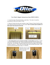
Figure 2-17. Minimum servicing space required
2.3 Delivery route inspection
During the receiving process, the entire system will need to be moved through the facility until it reaches
the data center or computer room where it will be installed. This section describes the considerations that
the installation team should make before receiving the system and moving it through the facility.
2.3.1 Walking path inspection
Walking paths must be clear of obstructions and wide enough to allow passage of the system to the site
where it will be unpacked. The following is a list of obstructions to consider when conducting a walking
path inspection:
Table 2-29. Space requirement specifications
Specification Value
Minimum front of rack space 1220mm (48in.)
Minimum rear of rack space 560mm (22in.)
FRONT
REAR
1220mm /
48in.
560mm /
22in.
Top of Rack

ActiveScale™ X100 Installation Guide
17
•Cables - consider removing cables, including ramped cable covers, from the walking path before
moving the pallet. Leaving the cables in place creates a safety hazard for the installation team and can
damage the cables.
•Lift locations - there may be locations along the walking path where the system must be lifted in
order to proceed. Make sure that lift equipment is available at this location on the day of the delivery.
•Elevators - ensure that any elevators that will be required to lift the equipment to the data center/
computer room are rated to carry the full load of the system plus passengers.
2.4 Airflow considerations
Ensure that both the front and rear of the ActiveScale X100 stay clear of any materials that may block or
disrupt the airflow in any way. Disrupting the airflow can cause the system to overheat, which may affect
performance or cause damage to the system.
The following rack airflow principles should be considered for best results:
• Controlled air conditioners that are functional and can sufficiently maintain specified system
operating temperatures should be located in the facility where the system will be installed.
• The airflow in and out of the equipment must not be restricted.
2.5 PDU connector types
This section provides information specific to the PDU connection types.
Table 2-30. Airflow requirements
Condition (fully configured) Non-operating Operating
Altitude -984 ft to 39,3711 ft
(-300 m to 12,000 m)
-984 ft to 10,000 ft
(-300 m to 3048 m)
Relative humidity 10% to 95% non-condensing 8% to 90% non-condensing
Temperature 40°F to 158°F
(-40°C to 70°C)
50°F to 95°F
(10°C to 35°C)
Temperature de-rating 33.8°F per 984.2 ft above 9842.5 ft
(1°C per 300 m above 3000 m)
33.8°F per 984.2 ft above 3116.8 ft
(1°C per 300 m above 950 m)
Temperature gradient 86°F (30°C)/hour 68°F (20°C)/hour
Thermal output N/A Partial configuration (one column
populated sleds):
• 8.53/11.26 KBTU/h
Full configuration (seven columns of
populated sleds):
• 21.83/ 25.25 KBTU/h
System Expansion Node kit:
• 0.665 at 0.785 KBTU/hour

ActiveScale™ X100 Installation Guide
18
Table 2-31. PDU connector type
2.6 Network requirements
The ActiveScale system provides six 10G Ethernet ports for connecting to a customer's network. However,
the customer must provide six fiber cable drops from the network to the rack. The fiber cable must be LC
to LC multi- mode fiber optic patch cable (LC multi-mode 50/125mm MMF OM3 or OM4 10Gb laser
optimized fiber). These cables must comply with the Ethernet 10GBASE-SR standard. Ensure that you do
not exceed the specified maximum 10GBASE-SR cable length for the cable type chosen. For example, do
not exceed a length of 400 m if you are using 10G OM4 multi-mode cables.
-
PDU type Plug standard Outlet
standard Frequency Phase Amps (per
phase) Supply range
Delta Server
Technology
NEMA L15-
30P
L15-30R 50/60Hz 3-Phase 30A 200-240V
Delta Server
Technology
NEMA L21-
30P
L21-30R 50/60Hz 3-Phase 32A 208V
WYE Server
Technology
IEC 60309 16A
4P+E
outlet
IEC 60309 16A
4P+E
plug
50/60Hz 3-Phase 16A 380-415V
WYE Server
Technology
IEC 60309 16A
3P+E
outlet
IEC 60309 16A
4P+E
plug
50/60Hz 3-Phase 32A 230V
Single- Phase
Server
Technology
NEMA L6-30P L6-30R 50/60Hz Single-Phase 24A 200-240V
Single- Phase
Server
Technology
IEC 60309 24A
2P+E
outlet
IEC 60309 24A
2P+E
plug
50/60Hz Single-Phase 32A 220-240V

ActiveScale™ X100 Installation Guide
19
3 System unpacking
This chapter describes how to unpack the ActiveScale X100. The unpacking process also includes
inspection recommendations to ensure that the system has not been damaged or tampered with.
Topics:
•Packaging inspection on page 20
•Unpacking the ActiveScale X100 on page 20

ActiveScale™ X100 Installation Guide
20
3.1 Packaging inspection
Important: Ensure that all ShockWatch and TiltWatch sensors are checked and
recorded.
As you unpack the system, look for obvious signs of damage. The following scenarios are the most
common ways a package can be damaged:
• Crushed corners caused by dropping the package.
• Split seams caused by excessive shearing force placed on the container.
• Punctures caused by a sharp object striking the packaging.
• Water damage caused by contact with a water source or storage in an overly humid environment.
3.2 Unpacking the ActiveScale X100
The ActiveScale X100 ships on a padded pallet containing mounting hardware and system unloading
ramps.
To unpack the ActiveScale X100:
1. On the cardboard side panels, verify that the ShockWatch and TiltWatch sensors have not been
tripped. If any of the sensors have been tripped, report the damages to Western Digital Corporation
Support.
2. Cut the plastic bands holding the top cap to the cardboard panels.
Figure 3-18. Removing the plastic bands
/