Page is loading ...

FIAT 500 1957-73
Workshop Manual
Autobooks
Models Covered
Fiat New 500
Fiat 500D
Fiat 500F
Fiat 500L
Fiat and Autobianchi Giardiniera

CHAPTER 1
THE ENGINE
1 :1
1 :2
1 :3
1 :4
1 :5
1 :6
1 :7
1 :8
1:9
1 :10
1 :11
Description
Engine removal (sedan—all versions)
Engine removal (station wagon)
Engine disassembly (sedan—all versions)
Engine disassembly (station wagon)
Cylinder head removal, servicing and
replacement
Timing gear overhaul
Crankcase and cylinders
Piston assembly
Connecting rods
Crankshaft and main bearings
1 :1 Description
The 'New 500' two-cylinder aircooled engine operates
on the four-stroke 'Otto Cycle' and is fitted directly to
the transmission unit which incorporates the rear drive
assembly as shown in FIG 1 :1 and FIG 1 :2.
With the power unit fitted at the rear several advantages
are obtained including better load distribution to the
wheels when the vehicle is loaded, elimination of propeller
shaft reducing the size of centre tunnel and better use of
available space.
The cylinder block comprises two cast iron cylinder
barrels with cooling fins. The bottom of the cylinders fit
into machined seats in the aluminium crankcase.
The aluminium crankcase carries eight studs on which
are located the two cylinder barrels with the aluminium
cylinder head on the top.
A two bush crankshaft of special cast iron is fitted into
the lower half of the crankcase. The crankshaft is
F500
9
provided with a counterweight and is hollow to allow for
lubrication.
The steel connecting rods have thin wall bearing halves
on the big-end, and bronze bushes in the small-end. The
offset piston pin is of steel and retained in the piston by
two circlips.
Light alloy pistons are used and are of the taper-oval-
shaped type with a maximum diameter at the base of the
skirt, along an axis perpendicular to the piston pin. Pistons
are fitted with four rings as follows, one compression at
the top, two standard oil scraper rings and one side slotted
oil scraper ring.
The one-piece aluminium cylinder head is finned to
provide a larger cooling surface and carries the inlet and
exhaust manifolds.
The inlet passages merge into a single centralized
flange onto which is mounted the carburetter. The exhaust
passages run almost parallel to the axis of the engine.
1 :12
1 :13
1 :14
1 :15
1 :16
1 :17
1 :18
1 :19
1 :20
1 :21
1 :22
Flywheel and starter ring gear
The oil pump
Lubrication, oil filter, relief valve
Valve timing
Valve stem to rocker clearance
Engine assembly (sedan—all versions)
Engine assembly (station wagon)
Power plant mounting
Adjustment of generator and fan belt drive
Modifications
Fault diagnosis

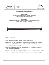
FIG 1:1 Left side view of the power plant to suit
500 Sedan
10
FIG 1:2 Right side rear three-quarter view of the power plant for 500 Station Wagon
Mounted on the top of the cylinder head is the overhead
valve rocker mechanism that is operated by a chain driven
camshaft through tappets and vertical pushrods.
The carburetter is of the downdraft type fitted with a
starting device that is controlled by a lever on the central
floor tunnel. A pleated paper element air cleaner and
silencer is fitted to the carburetter air intake. A mechanical
diaphragm type fuel pump operated from the camshaft by
a pushrod, supplies petrol to the carburetter from a fuel
tank located at the front of the vehicle.
Engine lubrication is provided by a gear pump driven
from the camshaft and mounted within the timing cover
drawing oil from the engine sump. The oil is cleaned by a
centrifugal filter situated at the rear end of the crankshaft
and pressure is controlled by a valve mounted on the
pump body. Crankcase ventilation is provided for through
a rubber hose connected to the top of the rocker cover.
The engine is cooled by air from a centrifugal blower
mounted on the generator shaft and housed in a specially
designed cowling conveying air to and around the engine.
The air temperature is governed by a special thermostat
fitted in the engine cowling.

FIG 1:3 Engine section through crankshaft, pistons and valves
F500
11

FIG 1:4 Engine cross-section through a cylinder
12

The interior of the car can be heated by the engine
warmed air being ducted into the front compartment and
controlled by a lever on the heating system tunnel.
Engine ignition is by a battery, ignition coil and distribu-
tor which is driven by a gear on the camshaft. The engine
is started by an electric starter motor which is mounted on
the gearbox casing and is controlled by a lever located
behind the gearchange lever.
The complete power unit is mounted by a spring support
at the centre of the rear body crossmember and by two
rubber pads mounted laterally to the gearbox.
1 :2 Engine removal (sedan—all versions)
To remove the engine from the car proceed as follows:
Raise the rear of the car and place on firmly based
stands placed under suitable brackets on the underside
of the body.
Disconnect the battery positive terminal clamp from the
battery terminal post. Release the clip securing the main
petrol pipe to the tank sender unit and ease the pipe
from the unit. Drain the oil from the engine sump into
a suitably sized container.
Disconnect the rear number plate light wire (see
FIG 1 :6). Release the engine compartment lid check
strap from its slot and separate the lid from the body by
sliding the hinge apart.
Remove the cables attached to the ignition coil, also
to the generator and the starter motor. Remove the
starter motor control tie rod.
Release the oil pressure
indicator cable, the main petrol pipeline at the pump,
the accelerator and starting device controls.
Remove the two hoses of the heating and cooling
system which are the input hose to the blower and the
hose for the car heating system. Release and lift out the
engine apron. Remove the starter motor mounting bolts
and carefully lift away the motor.
Using a garage hydraulic jack with suitable cradle (see
FIG 1:7) or a rope sling relieve the engine weight
from its mountings. Remove the nuts securing the
gearbox to the engine and the flywheel protection
apron.
Remove the bolts fixing the elastic support to the cross-
member. Remove the rear crossmember mounting nuts
noting that the engine earth cable is held by one
mounting nut and lift away the crossmember.
Carefully ease the engine away from the gearbox
ensuring that there is no strain placed on the clutch
shaft. Lower the engine to the floor taking care that no
weight is allowed on any of the attachments.
1
2
3
4
5
6
7
8
1 :3 Engine removal (station wagon)
To remove the engine from the station wagon proceed
as follows:
1 Raise the rear of the vehicle and place on firmly based
stands placed under suitable brackets on the underside
of the body.
2 Disconnect the battery positive terminal clamp from
the battery terminal post. Release the clip securing the
main petrol pipe to the tank sender unit and ease the
pipe from the unit. Drain the oil from the engine sump
into a clean dry container of suitable size.
3 Hold the rear door open and secure using string to stop
it swinging to the closed position. Secure the luggage
compartment floor panel in its upright position.
F500
13
4 Remove the cables attached to the ignition coil, also
to the generator and starter motor. Remove the starter
motor control tie rod. Release the oil pressure indicator
cable, the main petrol pipeline at the pump, the accele-
rator and starting device controls. Disconnect the air
filter housing.
5 Remove the hose connecting the car heating system
to the engine cowling. Disconnect the clip holding the
air pipe to the blower and carefully disconnect the pipe
from the blower cowling. Remove the starter motor
mounting bolts and carefully lift away the motor.
FIG 1:5 120.000 engine assembly: cross-section view
through a cylinder

LID CHECK ARM
FIG 1:6 Engine compartment lid open
LID LOCKING
HOOK
NUMBER PLATE
LAMP CABLE
NUMBER PLATE LAMP
CABLE JUNCTION
CROSS MEMBER ARR.2O74.
FIG 1 :7 Engine removal using the jack with cross-
member Arr.2074
6 Using a garage hydraulic jack with a suitable cradle
relieve the engine weight from its mountings. Remove
the nuts securing the gearbox to the engine.
7 Remove the nuts securing the rear bumper blade and
panel to the body. Note that the engine earth cable is
held by one mounting nut. Carefully dismantle the
engine elastic mounting or release the bracket from the
engine rear cover by removing the two nuts and washers.
Lift away the rear panel assembly carefully making sure
14
FIG 1:8 Engine components: crankcase, cylinder head,
timing sprockets cover
To dismantle the engine proceed as follows:
1 Remove the exhaust silencer by releasing the two
collars for attachment to the engine and the two con-
nections for the exhaust pipe. It will be noted that
there is one exhaust pipe connection on either side
of the cylinder head.
2 Place the engine on a firm wooden top bench. Remove
the two tappet cover retaining nuts and washers and
lift away the cover. Remove the connection for cooling
air delivery to the sump cooling ducts at the side of
the sump.
3 Remove the air cleaner after first releasing the two
bolts on the air cowling and the two nuts for the air
elbow connection to the carburetter.
4 Remove the generator drive belt by releasing the
three nuts so splitting the semi-pulley. Lift away the
drive belt.
5 Remove all the bolts securing the air conveyor
ducting to the cylinder head, to the crankcase and
also to the engine cowling assembly opposite to the
air conveyor. Release the accelerator control tie rod
and carefully lift away the air conveyor assembly
complete with the generator after first removing the
clamp fixing the generator to the crankcase.
1 :4 Engine disassembly (sedan—all versions)
that rear air ducting panels are not strained or the
mating faces damaged.
8 Carefully ease the engine away from the gearbox ensur-
ing that there is no strain placed on the clutch shaft.
Lower the engine to the floor taking care that no weight
is allowed on any of the attachments.

6 Release the ignition distributor support retaining nut
and lift away the distributor together with its support.
7 Remove all the mounting bolts of the engine cooling
cowling and lift away the assembly. Release the two
carburetter retaining nuts and carefully remove the
carburetter together with its drip tray.
8 Lift away the valve rocker assembly having first
released the two retaining nuts together with the plain
washers and lock washers. Carefully lift out the valve
rocker pushrods noting their relevant positions.
9 Slacken the four central cylinder head cap nuts and
the four conventional nuts in the order, shown in
FIG 1 :44 or 1 :46. Lift the cylinder head from the
barrels. If difficulty is experienced it is essential to use
Fiat tool A.40014 or a similar drilled plate, otherwise
serious damage could be caused if other means are
used (see FIG 1:9).
10 Remove the four pushrod sleeves and the casing
containing the oil ducting to the overhead valve gear.
11 Remove the fuel pump retaining nuts and washers
and lift away the pump. Carefully pull out the pump
control pushrod from the crankcase.
12 Remove the six screws holding the centrifugal oil filter
pulley cover and lift away the cover. Remove the
centrifugal filter mounting flange by unscrewing the
crankshaft central bolt. Also remove the timing cover
containing the oil pump gears and the oil pressure
regulating valve. Note the position of the nuts,
toothed and plain
washers for correct reassembly.
13 Release the four camshaft sprocket retaining bolts and
lift away the sprocket and timing chain. Using Fiat
pulley A.46020 or a large universal two-leg puller as
shown in FIG 1 :10 remove the crankshaft sprocket
and its body.
14 Carefully lift out the rocker pushrod tappets making a
note of their location and gently pull out the camshaft
making sure the front bearing bore is not damaged by
the cam lobes or distributor drive gear.
15 Mark the flywheel and crankshaft to ensure correct
reassembly and release the six flywheel retaining bolts
together with the lockwashers and lift away the fly-
wheel.
16 Using Fiat tool A.60156 on the two central studs, lock
the two cylinder barrels in place as shown in FIG 1 :11.
TOOL A. 40014
FIG 1:9 Tool A.40014 for cylinder head removal
F500
15
17 Turn the engine upside down ensuring that no weight
is placed on the studs and remove the oil sump and the
oil suction scoop.
18 Mark the connecting rods and end caps to ensure
correct reassembly and remove the end caps. Place the
engine on its side and remove the cylinder barrels
clamp. Ensure that the studs are clean and carefully
slide off the connecting rod-piston-cylinder assem-
blies from the crankcase.
19 Remove the six screws holding the rear main bearing
housing to the crankcase and lift away the housing.
Remove the six screws holding the front main bearing
housing to the crankcase and lift away the housing.
20 Carefully ease the crankshaft from the crankcase
moving it diagonally to assist withdrawal.
FIG 1:11 Cylinder hold-down tool A.601 56
TOOL A.60156
FIG 1 :10 Removing crankshaft sprocket with puller
A.46020
PULLER A.46020

STUD REMOVAL
PULLER 40010
FIG 1 :12 Removal of stud from crankcase by puller
A.40010
FIG 1 :13 Engine without blower cowling and cylinder
head cover
.SPACER AND CONNECTION
FOR ROCKER SHAFT
LUBRICATION TUBE
OILVAPOR
.VENT PIPE
CASINGS FOR PUSHRODS
(AND OIL RETURN
TO CRANKCASE
21 To ensure no damage occurs to the long cylinder
barrel mounting studs these may be removed using
Fiat puller A.40010 or a universal stud removal as
shown in FIG 1 :12.
1 :5 Engine disassembly (station wagon)
To dismantle the engine proceed as follows:
1 Remove the exhaust silencer and manifold by releasing
the four nuts holding the two flanges from the cylinder
head. Also disconnect the two silencer mounting
brackets and lift away the exhaust system (see
FIG 1 :2).
2 Place the engine on a firm wooden top bench. Release
the clip holding the tappet cover and lift away together
with the drip tray. Disconnect the fuel line and throttle
linkage at the carburetter and carefully lift away the
carburetter together with its insulator joint and gaskets.
3 Remove the generator drive belt by releasing the three
nuts so splitting the semi-pulley. Lift away the drive
belt.
16
FIG 1 :14 Tool A.60084 for valve and valve spring
removal
TOOL A. 60084
4 Remove all the bolts securing the air conveyor ducting
to the cylinder head and to the crankcase, carefully
separate the panels and lift away the separate panels
ensuring no damage is caused to the mating faces.
5 Release the ignition distributor retaining bolt and lift
away the distributor.
6 Remove the fuel pump retaining bolts and also the
three fuel pipe retaining clips and lift away the fuel
pump assembly together with the insulator, gaskets
and control rod.
7 Release the two valve rocker retaining nuts, note the
order of assembly of washers and ease away the rocker
shaft assembly from the top of the cylinder head.
Carefully lift out the valve rocker pushrods noting
their relevent positions for correct reassembly.
8 Slacken the four cylinder head cap nuts and the four
conventional nuts in the order shown in FIG 1 :46. Lift
the cylinder head away from the barrels. If difficulty is
experienced it is essential to use Fiat tool A.40014 or a
similar drilled plate as shown in FIG 1 :9, otherwise
serious damage could be caused if other means are
used.
9 Remove the four pushrod sleeves and the casing con-
taining the oil ducting to the overhead valve gear.
10 Remove the six screws holding the centrifugal oil filter
pulley cover and lift away the cover. Remove the
centrifugal filter mounting flange by unscrewing the
crankshaft central bolt. Also remove the timing cover
from the rear of the crankcase. Note carefully the posi-
tion of the nuts, toothed and plain washers for correct
reassembly.
11 Release the four camshaft sprocket retaining bolts
and lift away the sprocket and timing chain. Using
Fiat puller A.46020 or a large universal two-leg puller
as shown in FIG 1 :10 remove the crankshaft
sprocket and its key
12 Carefully lift out the rocker pushrod tappets making a
note of their location and gently pull out the camshaft
making sure that the front bearing bore is not
damaged by the cam lobes.

13 Remove all the bolts and washers joining the sump
casting to the crankcase making a special note of the
location of bolts of different lengths.
14 Mark the flywheel and crankshaft to ensure correct
reassembly and release the six flywheel retaining bolts
together with the lockwashers and lift away the fly-
wheel.
15 Using Fiat tool A.60156 on the two central studs, lock
the two cylinder barrels in place (see FIG 1 :11).
16 Turn the engine upside down ensuring that no weight
is placed on the studs.
17 Mark the connecting rods and end caps to ensure cor-
rect reassembly and remove the end caps. Place the
engine on its side and remove the cylinder barrels
clamp. Ensure that the studs are clean and carefully
slide off the connecting rod-piston-cylinder assem-
blies from the crankcase.
18 Remove the six screws holding the rear bearing hous-
ing to the crankcase and lift away the housing. Remove
the six screws holding the front main bearing housing
to the crankcase and lift away its housing.
19 Carefully ease the crankshaft from the crankcase
moving it diagonally to assist withdrawal.
20 To ensure no damage occurs to the long cylinder
barrel mounting studs these may be removed using
Fiat puller A.40010 or a universal stud remover as
shown in FIG 1 :12.
1 :6 Cylinder head removal, servicing and replace-
ment
Description:
The aluminium cylinder head is finned to increase the
cooling surface. Through bolts secure the head and the
two cylinders to the crankcase. The valves are controlled
by a camshaft through tappets, pushrods and rockers. The
connection between the head and the crankcase is via five
sleeves mounted directly between the head and crankcase,
and these accommodate the pushrods, lubricating oil and
passage for the crankcase gases. The cylinder head has
been
modified for the 110 F and later 120 engines as
they now incorporate a heater safety device as described
in Section 4:4.
FIG 1:15 Cylinder head
17
F500
The cylinder head should be removed whenever the
valves require attention or the engine to be decarbonized.
To remove the cylinder head proceed as follows:
1 Remove the air cleaner, carburetter, rocker cover and the
screws securing the blower conveyor to the cylinder
Removal of cylinder head:
FIG 1 :17 Installing a valve guide using Tool A.60153
provided with pilot bush
TOOL A. 60153-
WITH PILOT BUSH
FIG 1:16 Cleaning valve guides
WIRE BRUSH A.11417 / BIS

INTAKE
EXHAUST
INTAKE
EXHAUST
FIG 1 :18 Main specifications of intake and exhaust valves and valves guides (dimensions in mm)
head. Disconnect the two side exhaust manifolds.
Note the spark plug HT cables locations and dis-
connect from spark plugs.
2 Remove the rocker shaft pedestal- and lift away the
rocker gear. Extract the pushrods, making a careful
note of their location. Remove the cylinder head hold
down nuts in the order shown in FIG 1 :44 and using a
puller as shown in FIG 1 :9 lift off the head.
Dismantling the cylinder head:
1 Using Fiat valve spring compressor A.60084 or a uni-
versal spring compressor depress the valve spring as
shown in FIG 1 :14 and lift out the cotters. Release the
compressor and withdraw the lock cone, oil shield
(inlet valve only) upper spring cup, valve spring and
lower spring cup. Withdraw the valve from the under-
side of the head.
2 Dismantle the remaining three valve assemblies as
detailed above ensuring that all parts are kept in sets
for correct reassembly.
Inspection and servicing of the cylinder head :
1 Remove all carbon deposits from the combustion
chambers and valve ports using a rotary wire brush or a
set of scrapers.
2 Thoroughly clean the cylinder head and to test for dis-
tortion lightly coat the machined faces with 'Engineers
Blue' or lamp
black and place the cylinder head on a
surface plate. Carefully slide to and fro and any streaks
left behind will indicate a distorted surface. A distorted
head will not make a gas-tight seal with the cylinders
and must be entrusted to an expert for correction or,
in severe cases, renewed.
3 Carefully clean the valve guides as shown in FIG 1:16
using Fiat guide brush A.11417 bis. Should the guides
18
Reassembly is the reverse procedure to dismantling.
During assembly utmost cleanliness must be observed as
any abrasive material could find its way to the pistons and
cylinder bores causing unnecessary wear. Check that the
cylinder barrel mating face is clean to ensure correct
gasket sealing.
Reassembly of the cylinder head:
be worn then they should be removed using a press and
a suitable sized drift. The guides are press fitted with a
pinch fit of .00134 to .00244 inch. To install the guides
use Fiat tool A.601 53 as shown in FIG 1 :17. As the
guides have no stop ring during the press fitting, the
depth of insertion is determined by the Fiat tool. If the
tool is not available take the necessary depth measure-
ments before the old guides are removed. The normal
fit clearance between valve stem and guide is .00087 to
.00217 inch with a maximum wear limit of .0059 inch.
To check this see FIG 1:18.
4 The valve seats should always be reconditioned after
decarbonization. It is suggested that this operation be
left to a local service station with valve seat cutting
equipment. The valve seat angle for both inlet and
exhaust valves is 45° ± 5'.
5 Inspect the valves for soundness or distortion and if the
clearance between guide and stem is within the manu-
facturers wear tolerance of .0049 inch the valve may
be cleaned using a wire brush and the seating face
ground to an angle of 45°30' ± 5'. This again should
be left to the local service station.
Valve springs:
Thoroughly clean the valve springs of oil deposit and
inspect for cracks. It is advisable to check the free spring
height and if this dimension differs from the original
height, details of which are given in Technical Data, the
spring must be renewed. Any decrease in length indicates
that the spring has weakened.

Cylinder head installation:
To refit the cylinder head proceed as follows:
Place a new cylinder head joint on the cleaned faces of
the cylinder barrels. Insert the rocker pushrod and
lubrication pipe sleeves together with the relevant
gaskets and rings.
Fit the washers and nuts to the studs and tighten to
fingertight.
Tighten the nuts in the order shown in FIG 1 :44 and
FIG 1 :46 to a torque wrench setting of 18.1 Ibft. Reset
the torque wrench to a new setting of 23.9 Ibft and
tighten the nuts once more in the recommended order.
Replace the pushrods in the correct order.
Refit the rocker shaft ensuring correct location of the
lubrication tube to the rocker shaft and replace the
plain and lockwashers. Tighten the nuts to a torque
wrench setting of 15.2 Ibft. Reset the tappet to rocker
clearance adjustment.
Connect the two exhaust side manifolds to the cylinder
head. Using new gasket refit the spark plugs and HT
cables. Replace the rocker cover fitted with a new cork
gasket and blower conveyor to the cylinder head
securing screws. Refit the carburetter and reconnect its
fuel line and controls. Refit the air cleaner and elbow
and connect the rocker cover breather pipe (if fitted).
1
2
3
4
5
1 :7 Timing gear overhaul
Camshaft:
The cast iron camshaft is located in the crankcase and is
supported at either end in sets machined directly in the
crankcase. No bushes are used. The camshaft is driven by
a chain from the crankshaft at half engine speed and
operates the overhead valves through tappets, pushrods
and rockers (see
FIG
1
:20).
During engine overhaul the camshaft journals and cam
faces should be free of score marks or signs of seizure and
have a bright mirror finish.
The distributor drive gear should be inspected for tooth
wear which if excessive means that the camshaft must be
replaced.
Tappets:
The tappets should be inspected for signs of seizure or
excessive wear. The end surface that is in contact with the
camshaft should be smooth without signs of excessive
wear. Any slight scratches or indentations may be
removed using a very fine oil stone.
Pushrods and sleeves:
The pushrods operate in special axially resilient sleeves
that are compressed on assembly between the cylinder
head and the crankcase. It is through these sleeves that
the engine sump is vented also through which the oil
returning from the cylinder head passes.
Two rubber O-ring seals are fitted to each sleeve to
ensure an oil tight seal between the cylinder head and
crankcase. The sleeves should be checked for distortion
and exact equal length and when refitting new seals must
always be fitted.
The pushrods should be checked for straightness and
the two ends that contact the rocker setscrew and the
F500
19
The crankcase is an aluminium casting suitably ribbed
to ensure correct air cooling. The main bearing and cam-
shaft bearing bores are machined as also are the tappet
1 :8 Crankcase and cylinders
During valve gear overhauls the clearance between the
rocker shaft bore and the rocker must be checked. The
maximum permissable wear between these two parts is
.0059 inch. It is recommended that the part which is most
worn be renewed, or in extreme cases both parts.
Rocker and rocker shaft:
tappet seat must not show any signs of roughness or
excessive wear.
3 Oil shield (for intake valves only) 4 Snap ring
5 Rocker 6 Upper spring cup 7 Valve spring
8 Lower spring cup 9 Pushrod 10 Tappet
11 Oil seal ring 12 Pushrod sleeve 13 Seal ring
1 Intake valve 2 Upper cup lock
Key to Fiq
1
:20
FIG 1:20 Valve, pushrod and tappet assembly
FIG 1:19 Camshaft. The arrow points to the lube oil
outlet port

FIG 1:21 Finned cylinder. Letter A stamped on cylinder
indicates the class to which cylinder belongs, as referred
to its inside diameter
CLASS LETTER
FIG 1 :22 Cylinder measurement points
seats, gearbox companion flange and timing gear cover
mounting flange.
The cast iron cylinders are finned radially to increase the
cooling air surface and are located symmetrically on the
crankcase, each being held by four studs. The cylinders are
installed by sliding into the crankcase bores and finally
held in place by the cylinder head (see FIGS 1 :8 and
1 :21).
Inspect the cylinder bores for score marks, wear and
any other defects or damage. The clearance between the
piston maximum diameter and the cylinder bore should be
checked to ensure that it is within the maximum wear limit
of .0059 inch.
20
FIG 1 :23 Checking cylinder diameter by dial gauge
C.687 brought to zero with ring gauge C.672
DIAL GAUGE C 687
RING GAUGE C. 672
The cylinder height must be checked between the seat-
ing face on the crankcase and the top surface and this
dimension should be 3.5433 ±0006 inch.
If this dimension is less than specified the cylinder must
be renewed to prevent possible carbon deposits on the
piston crown and underside of combustion chamber
causing the piston to strike the cylinder head (see
FIG 1 :24).
Checking cylinder height:
This operation should bring the bore size to correspond
to the oversize piston sizes in order to obtain the correct
clearance between the piston and cylinder. These
limits
are given in Technical Data. It will be observed that the
cylinders are divided into three classes depending on the
bore diameter. The classes are identified by the letters 'A',
'B
1
and 'C, one of which will be stamped on the mating
face with the cylinder head as shown in FIG 1 :21. Pistons
are divided into three classes to correspond with the
cylinder bore sizes. Naturally the piston and bore must
belong to the same class. The maximum available piston
oversize is .0236 inch.
Pistons and rings for the Model 500 sports engine are
not available in oversize dimensions so if the cylinder bore
diameter is above the maximum wear limit new parts must
be fitted.
Honing or reboring cylinder bores:
It is essential that the diameter measurements are taken
at two different heights in the cylinder bore along both the
longitudinal and transverse axles as shown in FIG 1 :22.
It is recommended that to zero the internal micrometer
Fiat ring gauge C.672 is used (see FIG 1 :23).
If bore wear or ovality is between .0059 and .0079 inch
the cylinder bore may be honed. Should however the
wear limit of .0079 inch be exceeded then the bores must
be recut.

Insert a .0079 ± .00197 inch thick oil paper gasket
between the crankcase and cylinder bottom face and a
.0236 to .0275 inch thick graphitized asbestos gasket
between the cylinder and cylinder head. The compression
of the gaskets on assembly will eliminate any very small
differences between the two mating surfaces.
Inspection of tappet seats:
The tappet seats should be checked for scoring and
correct clearance which must not exceed .00315 inch.
Should the clearance be greater than the maximum
specified the seating may be reamed to oversize dimen-
sions as detailed in Technical Data. Tappets are avail-
able in .00197 and .00394 inch diameter oversize.
1 :9 Piston assembly
Inspection:
Before inspection the pistons must be thoroughly
cleaned and the ring grooves and piston head decarbo-
nized. Check for deep score marks and signs of distortion
or fracture especially around the skirt and piston pin areas.
Using a feeler gauge ensure that the piston clearances in
the bore do not exceed a maximum of .0059 inch for the
Model 500 engine and .0079 inch for the Model 500
sports engine (see FIG 1 :25). The measurements should
be taken at the bottom of the skirt and square to the piston
pin axis.
Should the clearance be greater than the maximum
permissible, the cylinders may be rebored and oversize
pistons fitted to m
atch them. Pistons are supplied in the
following oversizes, .0079, .0157 and .0236 inch. It
should be noted that oversize pistons and rings are not
available for the Model 500 sports engine so if the piston
to cylinder wall clearance is greater than the permissible
maximum limit the cylinder and piston assembly must be
renewed.
The piston ring to groove clearance must be checked as
shown in FIG 1 :26 and the ring gap when fitted as in
FIG 1 :27. In both cases the readings should be
compared with the piston data. Piston rings are available
in the same oversize classes as the pistons. When
installing piston rings the gap should be placed opposite to
the piston expansion stops. Ensure that the ring gaps are
scattered and not in a line.
FIG 1:24 Checking cylinder head mating face for level
Out-of-true should not exceed .00315 inch
F500
21
The installation of the piston and connecting rod should
be carried out on a clean workbench as shown in
Reassembly of piston:
Check that the fit between the piston pin and boss is a
pinch fit. If excessive clearance is found the boss may be
reamed and a .0079 inch diameter oversize piston pin
fitted. The pin to bore pinch fit must be between .0000 to
.0039 inch. At all times the pins should be installed only
after the piston has been heated in hot water to a tempe-
rature of 80°C. Upon reassembly of the piston to the
engine the expansion slot must be placed facing the cam-
shaft.
FIG 1 :26 Checking piston ring-to-land clearance
FEELER GAUGE C.316
FIG 1:25 Using feeler gauge C.316 to check piston-to-
cylinder wall clearance

FEELER GAUGE
Checking ring gap (ring in cylinder)FIG 1 :27
FIG 1 :28.
A universal piston ring compressor should be
used to keep the rings tight in their grooves. The correct
matching of the piston and connecting rod is described in
a later section of this chapter.
1 :10 Connecting rods
Checking rod bearing inserts and crankpin jour-
nals:
The big-end bearing halves are of the babbit lined thin
wall type and must not be modified in any way. Should
score marks or excessive wear be evident the bearing
inserts must be renewed. It is recommended that if the
bearing inserts are to be renewed due to wear the crank-
pins should be measured to see if regrinding is required.
Before regrinding the crankpins they should be
measured at the maximum point of wear to determine the
class of bearing undersize to be fitted after regrinding the
crankpins. Undersize bearing halves are available in the
following sizes .01, .02, .03 and .04 inch. The correct
bearing crankpin clearance is .00043 to .00240 inch and
must be checked as detailed in the following section.
Checking rod bearing insert to crankpin journal
clearance:
Before the crankshaft is installed into the engine after
overhaul the clearance must be checked to ensure that it is
within the manufacturers recommended limits. To check
the clearance proceed as follows:
1
2
Lubricate the crankpin and bearing inserts and install
the connecting rod together with its bearing halves on
the crankpin. Tighten the cap nuts to a torque wrench
setting of 23.9 Ibft.
Rotate the connecting rod around the crankshaft jour-
nal several times to seat the bearing insert correctly.
Remove the bearing end cap and carefully wipe away
all traces of the lubricant.
22
FIG 1 :29 Connecting rod components
Piston installer A.60154
FIG 1 :28
PISTON INSTALLER
A. 60154
If the clearance indicated is within the recommended
FIG 1 :31.
4
Place a piece of 'Plastigage type PG-1' along the full
width of the bearing insert along the crankshaft
longitudinal axis (see FIG 1 :30). Refit the bearing cap
and tighten the nuts to a torque wrench setting of
23.9 Ib ft. Remove the bearing cap and upon inspection
the 'Plastigage' will be found to have adhered to either
the crankpin or bearing insert and will have developed a
rectangular section. To determine the actual clearance
between the crankpin and bearing insert compare the
width of the flattened 'Plastigage' at its widest point
with the graduations on the envelope as shown in
3
PISTON RING

tolerance range of .00043 to .00240 inch or less than
.0059 inch the bearing inserts may be used again with-
out any need for regrinding. Should however the
clearance be greater than .0059 inch the inserts must be
renewed, using undersize inserts if the crankpin journals
have been reground.
It should be observed that 'Plastigage PG-1' is suitable
for measuring clearances up to .0030 inch so that if
carrying out 3 above produces no flattening of the
'Plastigage' the procedure must be repeated using
'Plastigage PR-1' which enables clearances up to
.0060 inch to be measured.
5
CRANKSHAFT
CON ROD
CALIBRATED STRIP
CON ROD
BEARING CAP
BEARING INSERT
FIG 1:30 'Plastigage' position for bearing insert-to-
crankpin journal clearance inspection
GRADUATION SCALE
BEARING .INSERT
CLEARANCE
READING
CALIBRATED
STRIP
CON ROD BEARING CAP
FIG 1 :31 Checking bearing insert-to-crankpin journal
clearance by comparing width of flattened 'Plastigage'
F500
23
To fit a replacement bush proceed as follows:
Firmly hold the connecting rod between soft faces in a
vice in such a way that it will not bend when working
on the small-end and using a suitably sized drift, remove
the old bush.
Use Fiat tool A.60155 or a suitably sized drift and care-
fully install the new bush which must be an interference
fit of between .0011 to .0036 inch.
A small slot must be cut in the bush to correspond with
the groove machined at the top of the connecting rod
so ensuring good lubrication between the bush and
piston pin.
1
2
3
The small end bush must be a firm fitting in the con-
necting rod and show no signs of deep scoring, scuffing,
ovality or excessive wear.
Should it be considered necessary, the bush may be
reamed using a Fiat expanding reamer U.0307 so that the
bush internal diameter permits an oversize piston pin to be
fitted with a clearance of .00020 to .00063 inch.
Little end bushing:
Installation of connecting rod bearing inserts:
During reassembly of the big-end bearing inserts the
parts must be thoroughly cleaned and then to reassemble
proceed as follows:
Ensure the bearing half to connecting rod surfaces are
perfectly smooth and free of score marks. Under no
circumstances may the bearing surface be reworked.
Check that the bearing half inserts are properly seated,
with the locating lugs fitting into their slots: this is
essential to obtain
correct bearing clearance.
As the circumference of the bearing half is greater than
the seats in connecting rod and cap the bearing must be
fitted so that the projection at each end of the bearing
half is equal.
Thoroughly lubricate all parts and tighten the end cap
nuts to a torque wrench setting of 23.9 Ib ft.
1
2
3
4
FIG 1:32 Connecting rod-piston assembly installation
on engine
REVOLUTION
DIRECTION
PISTON SLOT
CAMSHAFT
CONNECTING
ROD NUMBER

FIG 1:33 Checking crankshaft land-to-connecting rod
shoulder clearance
FIG 1:34 Engine front end without flywheel
Using an expanding reamer or Fiat reamer U.0307 ease
out the internal diameter of the bush to between .7874
to .7876 inch so that a standard piston may be fitted.
4
Piston-connecting rod assembly:
To assemble the piston to the connecting rod fit the
connecting rod to the piston so that the cylinder identifica-
tion number which is stamped on the connecting rod stem
and cap faces the expansion slot side in the piston as
shown in FIG 1 :32.
Lubricate the piston with engine oil, compress the
piston rings into their grooves and insert the piston con-
necting rod assembly into the cylinder barrel with the
identification numbers facing to the side opposite to the
camshaft as shown in FIG 1 :32.
If one or both connecting rods have been renewed the
new connecting rod cap and body must be stamped with
the cylinder identification number. The figures should be
stamped as shown in FIG 1 :32.
24
FIG 1:35 Camshaft end crankshaft supporting mem-
ber and bearing assembly, and spare main bearing
CRANKSHAFT
SUPPORTING MEMBER
(Camshaft end)
MAIN BEARING
Carefully inspect the crankshaft for minute cracks espe-
cially where there is a change in section. Should there
be any doubt always consult the official agents for
further advice.
Inspect the journals and crankpins. Should score marks
or ovality exist on the journals or crankpins they must
be reground and new undersize bearings fitted.
Undersize main bearings are obtainable in the sizes
.0079, .0157, .0236, .0314, .0394 inch ready fitted in
supports.
Undersize connecting rod bearings are obtainable in the
sizes .01, .02, .03 and .04 inch. The crank should be
reground to match the appropriate bearing undersize.
The clearance between the main bearing to journal
should be .00079 to .00256 inch and the connecting
rod bearing half to crankpin between .00043 to
.0024 inch.
2
1
The special cast iron crankshaft is hollow to allow for
the passage of lubrication oil. It is supported at its ends and
is provided with two cranks and a central counterweight.
The crankshaft plays an important part in the operation of
the lubrication system as its cavity provides a passage for
the oil flowing from the centrifugal filter.
Before inspecting the crankshaft thoroughly clean the
internal passage and drillings as well as the exterior and
then proceed as follows:
1:11 Crankshaft and main bearings
Upon reassembly the connecting rod cap nuts must be
tightened to a torque wrench setting of 23.9 Ib ft.

After the crankshaft has been reground it is important
that all traces of swarf are removed by constant washing
and then drying with a non-fluffy rag.
The clearance between the main bearings and journals
must be checked before installing the crankshaft in the
engine. It should also serve as a recheck after the
crankshaft has been reground.
Measure the maximum main bearing internal
diameter and the minimum journal diameter using
accurate measuring equipment. The clearance must not
exceed .0039 inch otherwise the journals must be
reground and undersize bearings fitted.
Undersize bearings with .0394 inch stock on the
internal diameter are also supplied unmounted. They
must be press fitted in the supports, the recommended
interference fit being .00039 to .00197 inch. After
pressing the bearing into the support, a hole is drilled in
the bearing in line with the location dowel hole in the
support. The hole is finished with a suitable expanding
reamer, such as Fiat U.0334, and the dowel pressed in,
noting that the hollow dowel fits in the flywheel end
support.
The next stage is to heat the assembly in an oven or
oil bath for a period of one hour at 150°C (302°F).
When the assembly has cooled to room temperature,
the bearing is reamed in a lathe to match the crankshaft
journal size.
3
Crankshaft oil seals:
Two inner spring rubber oil seals are located, one in a
special seat in the timing gear cover and the other in the
flywheel end of the crankshaft support and provide oil
tightness. These seals are shown in FIGS 1 :3 and 1 :34.
Whenever the engine is dismantled for overhaul these
seals should be carefully inspected for correct seating and
that the inner seal surface is not worn and that the contact
area is perfect both on the crankshaft and on the fan and
generator drive pulley hub.
Clutch shaft pilot bushing:
A self-lubricating bronze bush is fitted in the end of the
crankshaft as shown in FIG 1 :34 and provides a bearing
for the clutch shaft. Should the bush be worn use Fiat
puller A.40006/1 /2 to remove the worn bush. A new bush
should be fitted using a suitably sized drift.
1:12 Flywheel and starter ring gear
The flywheel should be inspected for wear at the clutch
driven plate contact area. It should be flat and have a
smooth finish.
The ring gear teeth should be cheeked for damage
which if evident, the ring gear must be replaced. To facili-
tate the fitting of a new ring gear on the flywheel, the new
ring gear should be heated in an oil bath to a temperature
of 80°C (176°F). Using a press gently ease the
expanded
ring gear over the flywheel and press fully home.
1:13 The oil pump
Sedan :
A helical-spur gear type oil pump is driven by the cam-
shaft through a front dog drive coupling. The gears are
F500
25
To remove the pump from the engine proceed as
follows:
Pump removal and reassembly:
Remove the engine rear central support from the timing
gear casing. Remove the filter cover pulley and lift
away the drive belt.
Release the hollow screw attaching the slinger and the
mounting flange of the filter on the crankshaft. Also
release the nuts fixing the timing gear cover to the
crankcase.
Remove the timing gear cover together with the oil
pump assembly and the pressure relief valve.
Lift out the oil pump suction scoop with the filter
screen attached from the sump.
Reassembly of the pump to the engine is the reverse
procedure to dismantling.
1
2
3
4
5
located in a special housing in the timing gear cover and
held in place by a cover plate. The oil pressure relief valve
is mounted on the drive gear shaft guide.
A pump suction scoop fitted with a filter screen is
secured in the crankcase and connects to a duct in the
timing gear case as shown in FIG 1 :36.
2
4
6
Key to Fig
1
:36
Rocker shaft
Ducts, cylinder head oil drain
Oil pressure relief valve
to centrifugal filter
9
with central oil gallery
12
Sump cooling air conveyor
indicator sending unit
Oil filler with vent valve
Line, oil delivery to rocker shaft
Level indicator rod
3
1
5
7
Gear pump
8 Oil duct
Centrifugal oil fitter
11
10
Crankshaft
Oil pump intake screen filter
13 Low oil pressure
FIG 1:36 Engine lubrication diagram

FIG 1:37 Lubrication diagram of engine 120.000
Key to Fig 1:37 1 Oil dipstick 2 Oil filler with vent valve 3 Centrifugal oil filter
4 Crankshaft, with central oil gallery 5 Low oil pressure indicator sending unit 6 Oil pressure relief valve 7 Gear pump
8 Camshaft, with central oil gallery 9 Oil suction filter from sump 10 Oil sump drain plug
11 Oil delivery line to rocker shaft 12 Rocker shaft 13 Head cover
Pump dismantling, inspection and reassembly:
Remove the lock ring and withdraw the pressure relief
valve and spring. Remove the oil pump cover plate and
ease out the gears and shaft.
Thoroughly clean all the parts and blow clean using a
compressed air jet. Inspect the timing gear cover for
cracks or distortion. Check that the inner duct for oil
delivery to the pump is clear of obstruction. Use a
compressed air jet to clean the passage.
Check the oil pump gear teeth for damage or excessive
wear and fit new gears if necessary. The recommended
backlash is .0059 inch with a maximum wear limit
giving a backlash of .0079 inch. Check the clearance
between the gear teeth and the housing walls in the
timing gear cover. The recommended clearance is .0012
to .0035 inch with a maximum of .0047 inch. Ensure
that the drive gear is firmly attached to its shaft. Upon
assembly there is a pinch fit of .0016 to .0031 inch
between the two parts.
The driven gear to shaft clearance upon assembly is
.00079 to .00236 inch with a maximum wear limit of
.0039 inch. Also check the width of the drive and driven
gears which when new should be .3937 to .3928 inch
with a minimum width of .3917. In service a spare drive
gear is supplied complete with its shaft.
26
4
3
2
1
Station wagon:
A helical-spur gear type oil pump is driven from the
lower end of the distributor drive spindle which is in mesh
with the camshaft. The gears are located in a special
housing in the bottom of the timing gear housing and are
held in place by a cover plate. The oil pressure relief valve
is located at the driven end of the camshaft.
A pump suction oil filter is fitted in the sump and this
connects to a duct in the timing gear case so supplying oil
to the pump (see FIG 1 :37).
Pump gears removal, inspection and reassembly:
To remove the pump gears from the timing gear cover
proceed as follows:
Inspect the filter screen on the end of the pump suction
scoop and remove any obstruction. If the screen is
damaged it must be renewed.
Check that the pump drive dog is a good fit on the cam-
shaft and that the dogs are not badly worn so as to
impair the pump operation.
Reassembly of the pump is the reverse procedure to
dismantling. Ensure that the pump cover piate is
correctly located by means of the dowel on the timing
gear cover.
5
6
7

Drain the oil sump to ensure that the oil does not syphon
out. Thoroughly clean the area around the pump body
(see FIG 1 :37).
Remove the end cover plate by releasing the retaining
bolts and washers. Carefully ease the driven gear down-
wards followed by the driving gear and shaft
Clean all parts removed and blow clean using a com-
pressed air jet. Inspect the timing gear cover pump area
for cracks or distortion. Check that the inner duct for oil
delivery to the pump is clear of obstruction. If in doubt
remove the drain plug and filler cap and use a com-
pressed air jet to clean the passage.
Check the gear teeth for damage or excessive wear,
ensure that the drive gear is firmly attached to its spindle
and that the end cover plate is not badly scored or pitted.
Fit new parts as necessary.
Reassembly is the reverse procedure to dismantling,
taking care that all parts are assembled clean and the
end cover plate seating correctly with a new gasket.
5
4
3
2
1
1:14 Lubrication, oil filter, relief valve
Description :
The engine is pressure lubricated through a gear type
pump which is incorporated in the timing gear cover and
driven from the camshaft by dogs or gears. The lubrication
circuits are shown in FIGS 1 :36 and 1 : 37.
The pump draws oil from the sump through a suction
horn fitted with a filter screen which is fixed to the crank-
case by a duct in the timing gear cover. This
supplies oil
to the pump.
Oil passes from the camshaft rear seat onto the crank-
shaft rear support where it flows into an adjacent chamber.
From here the oil flows through ducts in the crankshaft
from end to the centrifugal oil filter. The centrifugal filter,
which also acts as a pulley for the generator and blower
drive, rotates with the crankshaft.
Oil from the filter enters a passage in the crankshaft,
where it lubricates the main and connecting rod bearings
and passes from a special groove in the front main
bearing and ducting in the crankcase into which is
inserted the oil pressure warning sender unit, and also
the delivery pipe for oil to the overhead valve gear.
The pushrod sleeves provide the return path for the oil
from the cylinder head and delivers oil to the tappet gear
and the camshaft cams. The tappets are suitably drilled
to allow correct circulation of the oil. The tappets are
located in two casting cavities, one of which com-
municates with the timing gear housing and the other
one to the crankshaft front drain support drain.
The oil pressure is regulated by a pressure relief valve 5
(see FIG 1 :38) mounted at the rear end of the camshaft.
It comprises a hubbed disc which slides on a guide 6 of
the oil pump drive shaft 7. Under spring load 9 the valve
disc circumferentially closes an annular chamber which
communicates with the lubrication circuit. Excessive oil
pressure causes the disc to uncover the chamber.
Centrifugal oil filter:
The oil filter is of the centrifugal type comprising of
two flanges and an oil slinger. The filter is attached to the
rear end of the crankshaft as shown in FIG 1 :38. The
outside diameter of the oil slinger (see FIG 1 :39) is
smaller in diameter than that of the flanges but of such a
F500
27
Key to Fig 1:39 1 Drive pulley 2 Rotor hub
3 Seal ring 4 Oil slinger 5 Lockplate
6 Hub-to-crankshaft hollow screw 7, 8, 9 Pulley-to-hub
mounting screws, toothed washers and plain washers
FIG 1:39 Centrifugal oil filter components
Key to Fig 1 :38 Suction scoop 2 Hole in crankcase
3 Duct in timing sprocket cover 4 Timing sprocket cover
5 Oil pressure relief valve 6 Drive shaft guide and oil
pump cover 7 Oil pump driving gear shaft 8 Camshaft
9 Oil pressure relief valve spring
FIG 1:38 Engine longitudinal section through oil pump
/