Page is loading ...

MultiHop Radio Product Manual
151317 Rev 0 8/29/2011

Contents
MultiHop Radio Overview .........................................................................................................................4
MultiHop Application Modes ................................................................................................................................................5
Transparent Mode .......................................................................................................................................................5
Modbus Mode .............................................................................................................................................................5
Setting up the Network .............................................................................................................................8
Configure the Devices .........................................................................................................................................................8
Wiring for MultiHop Radios .........................................................................................................................................8
Setting the MultiHop Radio (Slave) ID ................................................................................................................................9
Binding MultiHop Radios to Form Networks ........................................................................................................................9
Slave and Repeater LED Behavior ..........................................................................................................................10
Master LED Behavior ...............................................................................................................................................10
Conduct a Site Survey .......................................................................................................................................................11
Conducting a MultiHop Site Survey from the LCD Menu ..........................................................................................11
Installing Your SureCross™ Radios ................................................................................................................................12
Mounting SureCross Devices Outdoors ....................................................................................................................13
Other Installation Requirements ..............................................................................................................................15
Installation Quick Tips ..............................................................................................................................................15
Basic Remote Antenna Installation ...........................................................................................................................16
Modbus Register Configuration ............................................................................................................22
40000s Standard Physical Inputs ......................................................................................................................................22
40400s Extra Inputs ..................................................................................................................................................22
40500s Standard Physical Outputs ...................................................................................................................................22
40900s Extra Outputs ...............................................................................................................................................22
41000s Input Parameters ..................................................................................................................................................22
Switch Power Input Parameters ................................................................................................................................23
42000s Output Parameters ................................................................................................................................................24
42950s Default Output Parameters ...................................................................................................................................25
43000s Discrete Input Parameters ....................................................................................................................................25
43300s Analog Input Parameters ......................................................................................................................................25
43500s Counter Input Parameters .....................................................................................................................................27
43600s H-Bridge Output Parameters ................................................................................................................................28
43600s Switch Power Output Parameters ................................................................................................................28
43700s Discrete Output Parameters .................................................................................................................................29
44000s Analog Output Parameters ...................................................................................................................................29
44150s Initialization Controls .............................................................................................................................................30
44400s Output Flash Pattern Parameters .........................................................................................................................30
44500s M-GAGE Parameters ............................................................................................................................................30
44800s Ultrasonic Input Parameters .................................................................................................................................32
46050s Battery Monitoring Parameters ............................................................................................................................33
51000s SDI-12 Parameter Descriptions ............................................................................................................................33
Configuration Examples .....................................................................................................................................................34
Configuring an Analog IN to use SP3 .......................................................................................................................34
Configuring for Acclima SDI-12 Sensors ..................................................................................................................35
Configuring for Decagon 5T3 SDI-12 Sensors .........................................................................................................35
Manufacturer Parameter Registers ....................................................................................................................................36
Device and System Parameters ........................................................................................................................................37
48200s Sample On Demand .....................................................................................................................................37
Agency Certifications .............................................................................................................................38
FCC Certification, 900 MHz, 1 Watt Radios ......................................................................................................................38
FCC Certification, 2.4GHz .................................................................................................................................................39
Contents
2 151317 Rev 0

Certified For Use in the Following Countries .....................................................................................................................40
Dimensions ..............................................................................................................................................43
Advanced Setup ......................................................................................................................................45
MultiHop Radio Menu System ...........................................................................................................................................45
Create the MultiHop Network by Manually Binding the Radios (using Menu Navigation) .................................................46
Conducting a Site Survey using Modbus Commands .......................................................................................................47
Using 10 to 30V dc to Power the MultiHop Radio and a Gateway ....................................................................................47
Using the Solar Supply to Power the MultiHop Radio and a FlexPower Gateway ............................................................48
Contents
3

MultiHop Radio Overview
MultiHop networks are made up of one master radio and many repeater and slave radios. The MultiHop networks are self-forming and
self-healing networks constructed around a parent-child communication relationship. The MultiHop Radio architecture creates a hierarchi-
cal network of devices to solve the most challenging wireless applications. A MultiHop Radio is either a master radio, a repeater radio, or
a slave radio.
• The single master device controls the overall wireless network.
• The repeater mode allows for range extension of the wireless network.
• The slave radios are the end point of the wireless network.
At the root of the wireless network is the master radio. All repeater or slave radios within range of the master radio connect as children of
the master radio, which serves as their parent. After repeater radios synchronize to the master radio, additional radios within range of the
repeater can join the network. The radios that synchronize to the repeater radio form the same parent/child relationship the repeater has
with the master radio: the repeater is the parent and the new radios are children of the repeater.
The network formation continues to build the hierarchical structure until all MultiHop radios connect to a parent radio. A MultiHop radio
can only have one designated parent radio. If a radio loses synchronization to the wireless network it may reconnect to the network
through a different parent radio.
For the simple example network shown below, the following relationships exist:
1
2
4
3
6
5
• Radio 1 is the master radio and is parent to radio 2 (repeater).
• Radio 2 (repeater) is child to radio 1 (master), but is parent to radios 3 (slave) and 4 (repeater).
MultiHop Radio Product Manual
4 www.bannerengineering.com - tel: 763-544-3164 151317 Rev 0

• Radio 4 (repeater) is child to radio 2 (repeater), but is parent to radios 5 and 6 (both slaves).
On the LCD of each device, the parent device address (PADR) and local device address (DADR) are shown.
MultiHop Master Radio. Within a network of MultiHop data radios, there is only one master radio. The master radio controls the overall
timing of the network and is always the parent device for other MultiHop radios. The host system connects to this master radio.
MultiHop Repeater Radio. When a MultiHop radio is set to repeater mode, it acts as both a parent and a child. The repeater receives
data packets from its parent, then re-transmits the data packet to the children within the repeater’s network. The incoming packet of
information is re-transmitted on both the radio link and the local serial link.
MultiHop Slave Radio. The slave radio is the end device of the MultiHop radio network. A radio in slave mode does not re-transmit the
data packet on the radio link, only on the local serial (wired) bus.
MultiHop Application Modes
The MultiHop radios operate in Modbus mode or transparent mode. Use the internal DIP switches to select the mode of operation. All
MultiHop radios within a wireless network must be in the same mode.
Transparent Mode
Use transparent mode for communication protocols other than Modbus. In transparent mode, the MultiHop radio packetizes data received
from the hardwired serial connection and transmits the packet to all radios within range. A wireless system by definition is a lossy link. It
is up to the host system protocol to guarantee the data integrity.
For reliable packet transmission, follow all rules for packet size and inter-character timing listed in the specifications and allow sufficient
time between packets to avoid overloading the MultiHop radio network. The time between packets varies based on the size of the net-
work.
Modbus Mode
Modbus application mode provides additional functionality to optimize RF packet routing performance and allows register-based access
and configuration of various parameters on the MultiHop radio. Modbus application mode requires that the system host device be running
a Modbus master program and that the master radio is connected directly to the host.
Packet Routing
In Modbus application mode, the master radio first discovers all connected Modbus slaves in the network, then uses the Modbus slave ID
contained in the incoming Modbus message to wirelessly route the packet only to the radio attached to the target Modbus slave. The
packet is then passed via the radio’s serial interface to the Modbus device where it is processed. This is entirely transparent to the user.
Direct packet by packet routing offers an advantage over broadcast addressing with MultiHop paths because each hop in the path can be
retried independently in the event of a packet error. This results in significantly more reliable packet delivery over MultiHop paths.
Modbus Slave IDs 01 through 10 are reserved for slaves directly connected to the host (local I/O). As such, polling messages addressed
to these devices are not relayed over the wireless link. Use Modbus Slaves IDs 11 through 61 for remote Modbus slaves — devices
serially connected to a data radio — allowing a maximum of 50 attached devices.
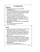
The figure below illustrates a basic wireless network operating in Modbus application mode. Slave devices may be any Modbus slaves,
including Banner's DX85 Modbus RTU Remote I/O devices or DX80 Gateways.
MultiHop Radio Product Manual
151317 Rev 0 www.bannerengineering.com - tel: 763-544-3164 5

Slave ID
12
Slave ID
14
Master radio
S1
S2
Host System
Slave ID
05
Slave ID
01
Slave ID
13
MultiHop Radio Registers and Radio IDs
The Modbus application mode also enables the host to access a radio’s internal Modbus registers to access radio configuration and
status information.
To enable access of a radio’s internal Modbus registers, the radio itself must be assigned a Modbus Slave ID, or MultiHop Radio ID,
using the rotary dials on the front of the device. The left rotary dial acts as the tens unit while the right rotary dial acts as the ones unit. To
set the slave ID to 12, set the left dial to 1 and the right dial to 2.
SureCross Radio Rotary Dials
1. Left dial - Represents the tens unit of the slave or device ID.
2. Right dial - Represents the ones unit of the slave or device ID.
When a Modbus message is received by the radio, the packet’s slave ID is compared to its own rotary dial address. If it matches, the
radio accesses its internal Modbus registers. If it does not match, the radio delivers the packet to the serial interface thereby interrogating
a connected Modbus slave. The range of acceptable Modbus Slave/MultiHop Radio IDs is from 11 to 61; a Slave ID setting of 0xFF
disables access to the MultiHop radio’s internal registers but still delivers addressed messages to Modbus slaves that are serially con-
nected to the radio. Detailed information about the contents and functions of the radio’s Modbus registers is provided in table 2.
All MultiHop Radio internal registers are defined as 16-bit holding registers (4xxxx). To access the internal registers, set the radio to
operate in Modbus mode (using the DIP switches) and set a valid MultiHop Radio ID (11 through 61).
*Note: The radio’s rotary dial address must not be a duplicate of an attached Modbus slave ID.
• Rotary dial positions 11 through 61. Valid wireless Modbus Slave IDs or MultiHop Radio IDs
• Rotary dial position FF. Devices set to FF are not directly addressed by the Modbus host system but can deliver the message to the
serially connected Modbus slaves
This example host system is connected to three hardwired devices: DX85 Remote I/O Modbus slave 01, DX85 Remote I/O Modbus slave
05, and the master MultiHop Radio.
Host messages for Modbus slaves 01 through 10 are ignored by the master radio. Messages for Modbus Slaves or MultiHop Radios 11
through 61 are sent out the wireless network.
MultiHop Radio Product Manual
6 www.bannerengineering.com - tel: 763-544-3164 151317 Rev 0

Slave ID
12
Slave ID
15
MultiHop Radio Master
(Radio ID 11)
MultiHop Radio Slave
(Radio ID 14)
Host System
Slave ID
05
Slave ID
01
Slave ID
13
DX85
DX85 Remote
I/O
MultiHop Radio Slave
(Radio ID 16)
DX85 Remote I/O
DX85
DX80 Gateway
DX80 Node
DX80 Node
MultiHop Radio Product Manual
151317 Rev 0 www.bannerengineering.com - tel: 763-544-3164 7

Setting up the Network
1
2
3
4
5
6
1 Rotary dials Sets the Modbus Slave ID when operating in Modbus
mode. (Not used on the Ethernet Data Radio.)
2 Push button 1 Single-click to advance across all top-level data radio
menus. Single-click to move down interactive menus,
once a top-level menu is chosen. (See MultiHop Ra-
dio Menu System.)
3 Push button 2 Double-click to select a menu and to enter manual
scrolling mode. Double-click to move up one level at
a time. Triple click to enter binding mode.
4 LED 1 and 2 Provide real-time feedback to the user regarding RF
link status, serial communications activity, and the er-
ror state.
5 LCD display Six-character display provides run mode user infor-
mation such as the number of packets sent and re-
ceived. This display allows the user to conduct a site
survey.
6 5-Pin M12 Euro-style
quick-disconnect port
The Euro-style power is used for serial connections
and power. (Not available on the Ethernet Data Ra-
dio.)
Configure the Devices
MultiHop Radios use the master device identification number to form groups of radios that communicate with each other. Follow the
procedure outlined below for binding radios to a particular master radio.
Accessing the DIP Switches
1. Disconnect the power to all MultiHop radios.
2. Unscrew the four screws that mount the cover to the bottom housing.
3. Remove the cover from the housing without damaging the ribbon cable or the pins the cable plugs into.
Setting the DIP Switches
1. Using DIP switches 7 and 8, set one unit to be the master radio (Sw 7 = OFF, Sw 8 = ON). By default, the MultiHop radios ship
from the factory configured to be repeater radios.
2. Using DIP switches 7 and 8, set the other data radios to be repeaters or slaves.
3. Set any additional DIP switches now. (See the DIP Switches section in the data sheet for the positions and descriptions.) By de-
fault, the MultiHop radios ship from the factory in Modbus mode. If you need the radio to be in Transparent mode, configure that
DIP switch now.
4. Power the devices to activate the DIP switch changes.
Wiring for MultiHop Radios
Connecting dc power to the communication pins will cause permanent damage. For FlexPower devices, do not apply more than 5.5V to
the gray wire.
The FlexPower Multihop radios will operate equally well when powered from the brown or gray wire. It is not necessary to supply both.
The power for the sensors can be supplied by the radio's SPx terminals or from the 10 to 30V dc used to power the radio.
MultiHop Radio Product Manual
8 www.bannerengineering.com - tel: 763-544-3164 151317 Rev 0

Wire No. Wire Color 10 to 30V dc (RS-485) FlexPower (RS-485) FlexPower (RS-232)
1 Brown 10 to 30V dc 10 to 30V dc 10 to 30V dc
2 White RS-485 / D1 / B / + RS-485 / D1 / B / + RS-232 Tx
3 Blue dc common (GND) dc common (GND) dc common (GND)
4 Black RS-485 / D0 / A / - RS-485 / D0 / A / - RS-232 Rx
5 Gray - 3.6 to 5.5V dc 3.6 to 5.5V dc
Setting the MultiHop Radio (Slave) ID
On a MultiHop radio, use the rotary dials to set the device’s MultiHop Radio ID. By factory default, Modbus Slave IDs 01 through 10 are
reserved for slaves directly connected to the host (local I/O). Polling messages addressed to these devices are not relayed over the
wireless link.
Use Modbus Slave IDs 11 through 61 for MultiHop master, repeater, and slave radios. Up to 50 devices (local slaves and remote slaves)
may be used in this system.
With the left dial acting as the left digit and the right dial acting as the right digit, the MultiHop
Radio ID can be set from 01 through 61.
Binding MultiHop Radios to Form Networks
To create your MultiHop network, bind the repeater and slave radios to the designated master radio.
Binding MultiHop radios ensures all MultiHop radios within a network communicate only with other radios within the same network. The
MultiHop radio master automatically generates a unique binding code when the radio master enters binding mode. This code is then
transmitted to all radios within range that are also in binding mode. After a repeater/slave is bound, the repeater/slave radio accepts data
only from the master to which it is bound. The binding code defines the network, and all radios within a network must use the same
binding code.
For Q45 Wireless Sensors, refer to the Q45 datasheet for binding and Slave ID instructions. For MultiHop M-HE models, refer to the M-
HE datasheet to set the Slave ID before following the binding instructions.
Step 1. Apply power to all MultiHop radios and place the MultiHop radios configured as slaves or repeaters at least two meters away
from the master radio.
Step 2. On the MultiHop master radio, triple click button 2. For MultiHop master radios with only one button, triple click the button.
For the two LED/button models, both LEDs flash red and the LCD shows *BINDNG and *MASTER. For single LED/button models, the
LED flashes alternatively red and green.
Step 3. On the MultiHop repeater or slave radio, triple click button 2. For repeaters or slaves with only one button, triple click the button.
The child radio enters binding mode and searches for any Master radio in binding mode. While searching for the Master radio, the two
red LEDs flash alternately. When the child radio finds the Master radio and is bound, both red LEDs are solid for four seconds, then both
red LEDs flash simultaneously four times. For M-GAGE Nodes, both colors of the single LED are solid (looks orange), then flash. For
Q45 radios, both the green and red are solid, then flash. After the slave/repeater receives the binding code transmitted by the master, the
slave and repeater radios automatically exit binding mode.
Step 4. Set the Slave ID. On MultiHop radios with rotary dials, use both rotary dials to assign a decimal MultiHop Radio ID between 11
and 61. The left rotary dial represents the tens digit (1–6) and the right dial represents the ones digit (0–9) of the MultiHop Radio ID.
For MultiHop M-HE* models, see the Setting the Slave ID instructions.
MultiHop Radio Product Manual
151317 Rev 0 www.bannerengineering.com - tel: 763-544-3164 9

Step 5. Repeat steps 3 through 4 for as many slave or repeater radios as are needed for your network.
Step 6. When all MultiHop radios are bound, exit binding mode on the master by double-clicking button 2. All radio devices begin to form
the network after the master data radio exits binding mode.
Child Radios Synchronize to the Parent Radios
The synchronization process enables a SureCross radio to join a wireless network formed by a master radio. After power-up, synchroni-
zation may take a few minutes to complete. First, all radios within range of the master data radio wirelessly synchronize to the master
radio. These radios may be slave radios or repeater radios.
After repeater radios are synchronized to the master radio, any radios that are not in sync with the master but can "hear" the repeater
radio will synchronize to the repeater radios. Each repeater “family” that forms a wireless network path creates another layer of synchro-
nization process. The table below details the process of synchronization with a parent. When testing the devices before installation, verify
the radio devices are at least two meters apart or the communications may fail.
Slave and Repeater LED Behavior
All bound radios set to slave or repeater modes follow this LED behavior after powering up.
Two Button/LED Models Single Button/LED
Models
Process
Steps
Response LED 1 LED 2 LED
1 Apply power to the radio - Solid yellow
(briefly)
Red and green
2 The slave/repeater searches for a parent device. Flashes red - Flashes red (1 per 3
sec)
3 A parent device is detected. The slave/repeater searches
for other parent radios within range.
Solid red - Solid red
4 The slave/repeater selects a suitable parent. - Solid yellow Solid red and green
(looks yellow/orange)
5 The slave/repeater attempts to synchronize to the selec-
ted parent.
- Solid red Solid red
6 The slave/repeater is synchronized to the parent. Flashes green - Flashes green
7 The slave/repeater enters RUN mode. Solid green, then
flashes green
Solid green, then flash-
es green
Serial data packets begin transmitting between the slave/
repeater and its parent radio.
- Flashes yellow Flashes red and green
(looks yellow/orange)
Master LED Behavior
All bound radios set to operate as masters follow this LED behavior after powering up.
Two Button/LED Models Single Button/LED
Models
Process
Steps
Response LED 1 LED 2 LED
1 Apply power to the master radio - Solid yellow Red and green
MultiHop Radio Product Manual
10 www.bannerengineering.com - tel: 763-544-3164 151317 Rev 0

Two Button/LED Models Single Button/LED
Models
Process
Steps
Response LED 1 LED 2 LED
2 The master radio enters RUN mode. Flashes green - Flashes green
Serial data packets begin transmitting between the mas-
ter and its children radios.
- Flashes yellow Flashes red and green
(looks yellow/orange)
Conduct a Site Survey
A site survey analyzes the radio signal between a MultiHop child radio and its parent and reports the number of data packets missed or
received at relative signal strengths.
Conducting a MultiHop Site Survey from the LCD Menu
Perform the site survey before permanently installing your network to pre-screen a site for its radio communication potential, compare link
quality in different locations in a factory, or assist with final antenna placement and aiming.
Site surveys can be conducted from either the master, repeater, or slave radios. A master radio is always a parent and the slave radios
are always children radios within the radio communication relationship. A repeater radio, however, may be both a child radio to the mas-
ter or another repeater and a parent radio to other repeater or slave radios. For a more detailed description of the parent-child relation-
ships, refer to the device data sheets.
MultiHop Master Radio
MultiHop Repeater Radio
MultiHop Slave Radio
Site Survey
Site Survey
Other radios bound within the same network remain synchronized to the network, but are blocked from sending data while the site survey
is running. The site survey analyzes the signal strength between the selected child and its parent radio only. Disable site survey on one
radio before initiating it from another.
Radios in site survey mode have a solid green LED for the duration of the site survey and the LCD display scrolls the results. Because
the statistics represent the lesser of the round-trip results, one person can ascertain the link quality from either device.
Single-click button 2 to pause or resume autoscrolling the site survey results. While paused, button 1 single-step advances through the
four signal strength categories: green, yellow, red, and missed. Double-click button 2 to exit the results display. (Refer to the data sheet
for the menu structure.)
1 On a data radio device, press button 1 until the display reads *SITE.
When the site survey runs, serial and I/O data radio communication between that parent and its children stops.
2 Single-click button 2 to enter the Site Survey menu.
Master radio: The displays reads CHLDRN. Repeater radio: The display reads PARENT. Slave radio: The display reads PA-
RENT.
3 From the Master
Single-click button 2 to display the
child radio’s device address. (A ra-
From the Repeater
Single-click button 1 to cycle between PA-
RENT and CHLDRN.
From the Slave
Single-click button 2 to display PA-
RENT.
MultiHop Radio Product Manual
151317 Rev 0 www.bannerengineering.com - tel: 763-544-3164 11

dio’s device address is displayed
under its *RUN menu).
Single click button 1 to scroll be-
tween all the master radio’s chil-
dren. When you reach the child ra-
dio you want to run the site survey
with, single-click button 2.
Single-click button 2 to select PARENT or
CHLDRN.
If conducting the site survey with one of the re-
peater’s children, single-click button 1 to scroll
among a repeater’s children radios. (Each da-
ta radio’s device address is displayed under its
*RUN menu.)
Single-click button 2 at the device address
screen to select the child or parent and begin
the site survey.
Single-click button 2 to begin the site
survey.
The site survey begins. LED 2 on both the parent and child radios flash for every received RF packet. To indicate the parent
is in site survey mode, LED 1 is a solid green. The data radio analyzes the quality of the signal between the parent and child
by counting the number of data packets received and measuring the signal strength (green, yellow, and red).
4 Examine reception readings (G, Y, R, M) of the devices at various locations. M displays the percent of missed packets while
G, Y, and R display the percent of received packets at those signal strengths. These values are continuously updated as long
as the site survey is running.
GRN = GREEN excellent signal strength; YEL = YELLOW good signal strength; RED = RED marginal signal strength; MIS =
Percentage of missed packets. When possible, install all devices to optimize the percentage of YELLOW and GREEN data
packets received.
5 While the site survey is in process, single-click button 2 to pause or resume autoscrolling the site survey results. While
paused, button 1 single-step advances through the four signal strength categories: green, yellow, red, and missed. Double-
click button 2 to exit the results display.
6 Double-click button 2 on either the child or the parent device.
Site survey ends and the devices automatically resume operation.
Interpreting the MultiHop Site Survey Results
Site survey mode works by having two radios (one child and one parent) repeatedly exchange data packets. For every round-trip ex-
change of data, the child data radio keeps track of the weaker of the two paths. Both units report the statistics as a percentage on their
LCD display.
The reports consists of sorting the data into one of four categories: Green, Yellow, Red, or Missed Packets.
• Green indicates strong signal,
• Yellow is less strong but still robust,
• Red means the packet was received but has a margin of less than 15 dB, and
• A missed packet means the data did not arrive or contained a checksum error. (During normal operation, missed packets are re-tried
until they are received without errors. During a site survey, missed packets are not re-tried.)
For applications with only a few hops, the system can tolerate up to 40% missed packets without serious degradation, but situations with
more missed packets should be reviewed for proper antenna selection and placement, cabling, and transmit power levels. If your applica-
tion includes many hops, modify the installation and antenna placement to reduce the missed packet count.
Any radio can initiate a site survey. Other radios on the same network ID remain synchronized to the network, but are blocked from
sending data while the site survey is running. In installations with multiple child radios, the site survey analyzes the signal strength be-
tween the selected child and its parent radio only. Disable site survey on one radio before initiating it from another.
Radios in site survey mode have a solid green LED for the duration of the site survey and the LCD display scrolls the results. Because
the statistics represent the lesser of the round-trip results, one person can ascertain the link quality from either device.
Installing Your SureCross™ Radios
The following are some recommendations for installing your wireless network components.
MultiHop Radio Product Manual
12 www.bannerengineering.com - tel: 763-544-3164 151317 Rev 0

Mounting SureCross Devices Outdoors
Mounting SureCross Devices Outdoors
Use a Secondary Enclosure. For most outdoor applications, we recommend installing your
SureCross devices inside a secondary enclosure.
For a list of available enclosures, refer to the Accessories list.
Point Away From Direct Sunlight. When you are not using a secondary enclosure, mini-
mize the damaging effects of ultra-violet radiation by mounting the devices to avoid facing
intense direct sunlight.
• Mount under an overhang or other source of shade,
• Install indoors, or
• Face the devices north when installing outside.
For harsh outdoor applications, consider installing your radio inside a secondary enclosure.
For a list of available enclosures, refer to the Accessories list.
Mount Vertically to Avoid Collecting Rain. When possible, mount the devices where rain
or snow will drain away from the device.
• Mount vertically so that precipitation, dust, and dirt do not accumulate on permeable
surfaces.
• Avoid mounting the devices on flat or concave surfaces, especially if the display will be
pointing up.
Moisture and Condensation. If condensation is present in any device, add a small desic-
cant packet to the inside of the radio.
To help vent the radios, Banner also sells a vented plug (model number BWA-HW-031) for
the 1/2" NPT port of the SureCross radios.
Vented plug for the 1/2" NPT port.
Watertight Glands and NPT Ports
Watertight Glands and Plugs
To make glands and plugs watertight, use PTFE tape and follow these steps.
MultiHop Radio Product Manual
151317 Rev 0 www.bannerengineering.com - tel: 763-544-3164 13

To make the glands watertight:
1. Wrap four to eight passes of polytetrafluoroethylene (PTFE) tape around the
threads as close as possible to the hexagonal body of the gland.
2. Manually thread the gland into the housing hole. Never apply more than 5 in-
lbf of torque to the gland or its cable clamp nut.*
Seal any unused PG-7 access holes with one of the supplied black plastic plugs. To install a watertight PG-7 plug:
1. Wrap four to eight passes of PTFE tape around the plug’s threads, as close as possible to the flanged surface.
2. Carefully thread the plastic plug into the vacant hole in the housing and tighten using a slotting screwdriver. Never apply more than
10 in-lbf torque to the plastic plug.
* This is not a lot of torque and is equivalent to the torque generated without using tools. If a wrench is used, apply only very light pres-
sure. Torquing these fittings excessively damages the device.
Watertight NPT Plugs
Seal the 1/2” NPT port if it is not used. To install a watertight NPT plug:
1. Wrap 12 to 16 passes of PTFE tape evenly across the length of the threads.
2. Manually thread the plug into the housing port until reaching some resistance.
3. Using a 9/16” crescent wrench, turn the plug until all the plug’s threads are engaged by the housing port or until the resistance
doubles. Do not overtighten as this will damage the SureCross unit. These threads are tapered and will create a waterproof seal
without overtightening.
* This is not a lot of torque and is equivalent to the torque generated without using tools. If a wrench is used, apply only very light pres-
sure. Torquing these fittings excessively damages the device.
Replacing the Rotary Dial Access Cover
Check the rotary dial access cover o-ring every time the access cover is removed. Replace the o-ring when it is damaged, discolored, or
showing signs of wear.
The o-ring should be:
• Seated firmly against the threads without stretching to fit or without bulging loosely, and
• Pushed against the flanged cover.
When removing or closing the rotary dial access cover, manually twist the cover into posi-
tion. Do not allow cross-threading between the cover and the devce's face.
Once the cover is in place and manually tightened, use a small screwdriver (no longer than
five inches total length) as a lever to apply enough torque to bring the rotary dial access
cover even with the cover surface.
Replacing the Main Body Gasket
Check the main body gasket every time a SureCross™ device is opened.
MultiHop Radio Product Manual
14 www.bannerengineering.com - tel: 763-544-3164 151317 Rev 0

Replace the gasket when it is damaged, discolored, or showing signs of wear.
The gasket must be:
• Fully seated within its channel along the full length of the perimeter, and
• Positioned straight within the channel with no twisting, stress, or stretching.
Other Installation Requirements
Reduce Chemical Exposure
Before installing any devices in a chemically harsh environment, contact the manufacturer for more information regarding the life-expect-
ancy. Solvents, oxidizing agents, and other chemicals will damage the devices.
Minimize Mechanical Stress
Although these radio devices are very durable, they are sophisticated electronic devices that are sensitive to shock and excessive load-
ing.
• Avoid mounting the devices to an object that may be shifting or vibrating excessively. High levels of static force or acceleration may
damage the housing or electronic components.
• Do not subject the devices to external loads. Do not step on them or use them as handgrips.
• Do not allow long lengths of cable to hang from the glands on the Gateway or Node. Cabling heavier than 100 grams should be
supported instead of allowed to hang from the housing.
It is the user’s responsibility to install these devices so they will not be subject to overvoltage transients. Always ground the devices in
accordance with local, state, or national regulations.
Installation Quick Tips
The following are some quick tips for improving the installation of wireless network components.
Create a Clear Communication Path
Wireless communication is hindered by radio interference and obstructions in the path between the transmitter and receiver. To achieve
the best radio performance, carefully consider the installation locations for the Gateways and Nodes and select locations without obstruc-
tions in the path.
For more information about antennas, please refer to the Antenna Basics reference guide, Banner document p/n 132113.
Increase the Height of the Antennas
Position the external antenna vertically for optimal RF communication. If necessary, consider changing the height of the SureCross radio,
or its antenna, to improve reception. For outdoor applications, mounting the antenna on top of a building or pole may help achieve a line-
of-sight radio link with the other radios in the network.
MultiHop Radio Product Manual
151317 Rev 0 www.bannerengineering.com - tel: 763-544-3164 15

No line of sight
Line of sight
Node
Gateway
Avoid Collocating Radios
When the radio network’s master device is located too close to another radio device, communications between all devices is interrupted.
For this reason, do not install a Gateway device within two meters of another Gateway or Node.
Be Aware of Seasonal Changes
When conducting the initial Site Survey, the fewest possible missed packets for a given link is better. However, seasonal changes may
affect the signal strength and the total signal quality. Radios installed outside with 50% missed packets in the winter months may have
80% or more missed packets in the summer when leaves and trees interfere with radio reception.
During spring and summer, leaves may
block more of the radio signal.
A good signal strength in winter doesn’t
always mean you’ll get the same signal
strength the rest of the year.
Node
Gateway
Node
Gateway
Basic Remote Antenna Installation
A remote antenna system is any antenna system where the antenna is not connected directly to the radio. These systems typically use
coaxial cable to connect the antenna to the radio. When installing a remote antenna system, always include a lightning arrestor or coaxial
surge suppressor in the system. Remote antenna systems installed without surge protection invalidate the warranty of the radio devices.
Surge suppressors should be properly grounded and mounted at ground level near where the cabling enters a building. Install the surge
suppressor indoors or inside a weatherproof enclosure to minimize corrosion or component deterioration. For best results, mount the
MultiHop Radio Product Manual
16 www.bannerengineering.com - tel: 763-544-3164 151317 Rev 0

surge suppressor as close to the ground as possible to minimize the length of the ground connection and use a single-point ground
system to avoid creating ground loops.
For more detailed information about how antennas work and how to install them, refer to Antenna Basics, Banner document 132113 (also
included as a chapter within the product manual).
1
2
3
4
1. Antenna mounted remotely from the radio device.
2. Coaxial cable
3. Surge suppressor
4. Ground wire to a single-point ground system
I/O Isolation. When connecting analog and discrete I/O to external equipment such as VFDs (Variable Frequency Drives), it may be
appropriate to install interposing relays and/or loop isolation devices to protect the DX80 unit from transients, noise, and ground plane
interference originating from devices or the environment. Contact Banner Engineering Corp. for more information.
Weatherproofing Remote Antenna Installations
Prevent water damage to the cable and connections by sealing the connections with rubber splicing tape and electrical tape.
Step 1: Verify both connections are clean and dry before connecting the antenna cable to the antenna or other cable and hand-tighten-
ing.
Step 2: Tightly wrap the entire connection with rubber splicing tape.
Begin wrapping the rubber splicing tape one inch away from the connection and continue wrapping until you are one inch past the other
end of the connection. Each new round of tape should overlap about half the previous round.
Step 3: Protect the rubber splicing tape from UV damage by tightly wrapping electrical tape on top of the rubber splicing tape. The
electrical tape should completely cover the rubber splicing tape and overlap the rubber tape by one inch on each side of the connection.
Antenna Installation
Always install and properly ground a qualified surge suppressor when installing a remote antenna system. Remote antenna configura-
tions installed without surge suppressors invalidate the manufacturer's warranty.
MultiHop Radio Product Manual
151317 Rev 0 www.bannerengineering.com - tel: 763-544-3164 17

Always keep the ground wire as short as possible and make all ground connections to a single-point ground system to ensure no ground
loops are created. No surge suppressor can absorb all lightning strikes. Do not touch the SureCross™ device or any equipment connec-
ted to the SureCross device during a thunderstorm.
Mounting an RP-SMA Antenna Directly to the Cabinet
This antenna mounts directly to the outside of the box, with the SureCross device mounted inside the box.
This situation may be used either inside or outside the building.
1
3
4, 5
2
Model Number Description
1 BWA-9O2-C Antenna, Omni, 902-928 MHz, 2 dBd, Rubber Swivel, RP-SMA MALE
BWA-2O2-C Antenna, Omni, 2.4 GHz, 2 dBd, Rubber Swivel, RP-SMA MALE
BWA-2O5-C Antenna, Omni, 2.4 GHz, 5 dBd, Rubber Swivel, RP-SMA MALE
BWA-2O7-C Antenna, Omni, 2.4 GHz, 7 dBd, Rubber Swivel, RP-SMA MALE
2 BWC-LMRSFRPB Surge Suppressor, Bulkhead, RP-SMA Type, 900 MHz/2.4 GHz
3 BWC-1MRSFRSB02 RG58 Cable, RP-SMA TO RP-SMA Female Bulkhead, 0.2 m
BWC-1MRSFRSB1 RG58 Cable, RP-SMA TO RP-SMA Female Bulkhead, 1 m
BWC-1MRSFRSB2 RG58 Cable, RP-SMA TO RP-SMA Female Bulkhead, 2 m
BWC-1MRSFRSB4 RG58 Cable, RP-SMA TO RP-SMA Female, Bulkhead, 4 m
MultiHop Radio Product Manual
18 www.bannerengineering.com - tel: 763-544-3164 151317 Rev 0

Model Number Description
4 DIN-35-105 DIN Rail section, 105 mm long, 35 mm design
5 SMBDX80DIN DIN Rail Bracket Assembly for DX70 and DX80 models.
Mounting an RP-SMA Antenna Remotely
This antenna mounts remotely from the box, with the SureCross device mounted inside the box.
This situation may be used either inside or outside the building, though a Yagi antenna is usually used in outdoors applications while an
omni-directional antenna may be used either inside a building or outside.
1
2
3
4
5, 6
7, 8
9
Model Number Description
1 BWA-9O2-C Antenna, Omni, 902-928 MHz, 2 dBd, Rubber Swivel, RP-SMA MALE
BWA-9O5-C Antenna, Omni, 902-928 MHz, 5 dBd, Rubber Swivel, RP-SMA MALE
BWA-2O2-C Antenna, Omni, 2.4 GHz, 2 dBd, Rubber Swivel, RP-SMA MALE
BWA-2O5-C Antenna, Omni, 2.4 GHz, 5 dBd, Rubber Swivel, RP-SMA MALE
BWA-2O7-C Antenna, Omni, 2.4 GHz, 7 dBd, Rubber Swivel, RP-SMA MALE
2 BWC-1MRSFRSB02 RG58 Cable, RP-SMA TO RP-SMA Female Bulkhead, 0.2 m
BWC-1MRSFRSB1 RG58 Cable, RP-SMA TO RP-SMA Female Bulkhead, 1 m
BWC-1MRSFRSB2 RG58 Cable, RP-SMA TO RP-SMA Female Bulkhead, 2 m
BWC-1MRSFRSB4 RG58 Cable, RP-SMA TO RP-SMA Female, Bulkhead, 4 m
3 BWC-LMRSFRPB Surge Suppressor, Bulkhead, RP-SMA Type, 900 MHz/2.4 GHz
4 BWC-1MRSFRSB02 RG58 Cable, RP-SMA TO RP-SMA Female Bulkhead, 0.2 m
MultiHop Radio Product Manual
151317 Rev 0 www.bannerengineering.com - tel: 763-544-3164 19

Model Number Description
BWC-1MRSFRSB1 RG58 Cable, RP-SMA TO RP-SMA Female Bulkhead, 1 m
BWC-1MRSFRSB2 RG58 Cable, RP-SMA TO RP-SMA Female Bulkhead, 2 m
BWC-1MRSFRSB4 RG58 Cable, RP-SMA TO RP-SMA Female, Bulkhead, 4 m
5 DIN-35-105 DIN Rail section, 105 mm long, 35 mm design
6 SMBDX80DIN Bracket Assembly, DIN Rail, for DX80
7 BWA-EF14128 Fiberglass enclosure, 14”x 12” x 8”
8 BWA-PA1412 Internal panel, 14” x 12”
9 * DX81 DX81 FlexPower Battery Supply Module
DX81P6 DX81P6 FlexPower Battery Supply 6-Pack
PS24DX Power Supply, 24V dc, 200 mA
PS24DXSR Power Supply, 24V dc, 200 mA, Solid State Relay
* This example image depicts a DX80 radio with a PS24x power supply. The example installation may also work with the DX70 radios or
MultiHop radios. However, the DX81 and DX81P6 FlexPower Battery Supply Modules can only power FlexPower devices. The battery
supply modules cannot be used with any 10-30V dc-only powered devices and cannot be used with the DX70 radios.
Mounting N-Type Antennas Remotely
This antenna mounts remotely from the box, with the SureCross device mounted inside the box.
This situation may be used either inside or outside the building, though a Yagi antenna is usually used in outdoors applications while an
omni-directional antenna may be used either inside a building or outside.
1
3
4
5, 6
2
7, 8
9
MultiHop Radio Product Manual
20 www.bannerengineering.com - tel: 763-544-3164 151317 Rev 0
/