Page is loading ...

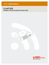
Configurable FlexPower Node with discrete and thermocouple I/O
The SureCross® wireless system is a radio frequency network with integrated I/O that can
operate in most environments and eliminate the need for wiring runs. Wireless networks are
formed around a Gateway, which acts as the wireless network master device, and one or
more Nodes.
• Wireless industrial I/O device with up to two selectable discrete inputs, one NMOS dis-
crete output, and four thermocouple inputs (defaults to J-type)
• One thermistor input used for integrated cold junction compensation (CJC)
• Selectable transmit power levels of 250 mW or 1 Watt and license-free operation up to 4
watt EIRP, with a high-gain antenna, in the U.S. and Canada for 900 MHz
• FlexPower® power options allows for +10 to 30V dc, solar, and battery power sources for
low power applications.
• DIP switches for user configuration
• Frequency Hopping Spread Spectrum (FHSS) technology and Time Division Multiple Ac-
cess (TDMA) control architecture ensure reliable data delivery within the unlicensed In-
dustrial, Scientific, and Medical (ISM) band
• Transceivers provide bidirectional communication between the Gateway and Node, in-
cluding fully acknowledged data transmission
• Lost RF links are detected and relevant outputs set to user-defined conditions
For additional information, the most recent version of all documentation, and a complete list of accessories, refer to Banner Engineering's
website, www.bannerengineering.com/surecross.
Models Frequency Power Housing I/O
DX80N9X2S-P3
900 MHz ISM
Band
10 to 30V dc or battery supply mod-
ule
IP67, NEMA
6
Inputs: Two selectable discrete, four ther-
mocouple, one thermistor for CJC
Outputs: One NMOS sinking discrete
DX80N9X1S-P3E 10 to 30V dc or integrated battery
IP54, NEMA
4
DX80N2X2S-P3
2.4 GHz ISM
Band
10 to 30V dc or battery supply mod-
ule
IP67, NEMA
6
DX80N2X1S-P3E 10 to 30V dc or integrated battery
IP54, NEMA
4
DX80...C (IP20; NEMA 1) models are also available. To order this model with an IP20 housing, add a C to the
end of the model number: DX80N9X2S-P3C.
The integrated battery models are also available without batteries. If you purchase a model without the bat-
tery, Banner Engineering recommends using the XENO XL-205F battery or equivalent. For DX99 models, on-
ly a XENO XL-205F battery is certified.
WARNING: Not To Be Used for Personnel Protection
Never use this device as a sensing device for personnel protection. Doing so could lead to serious
injury or death. This device does NOT include the self-checking redundant circuitry necessary to allow its
use in personnel safety applications. A sensor failure or malfunction can cause either an energized or de-
energized sensor output condition.
Important: Never Operate 1 Watt Radios Without Antennas.
To avoid damaging the radio circuitry, never power up SureCross Performance or SureCross MultiHop (1
Watt) radios without an antenna.
SureCross Performance FlexPower Node
P/N 155863_web
Rev. C
11/7/2012

The SureCross® Performance Wireless Network
The SureCross® Performance wireless I/O network provides reliable monitoring without the burden of wiring or conduit installation. The
SureCross wireless network can operate independently or in conjunction with a host system, PLC, and/or PC software.
Each wireless network system consists of one Gateway and one or more Nodes. Devices ship with factory defined inputs and outputs
that may be all discrete, all analog, or a mix of discrete and analog I/O.
Gateway
Node
Node
FlexPower Node with
integrated battery
The SureCross® Performance network is a deterministic system—the network identifies when the radio signal is lost and drives relevant
outputs to user-defined conditions. Once the radio signal is reacquired, the network returns to normal operation.
SureCross® Performance Gateways and Nodes
A Gateway is the master device within each radio network. Every wireless network must have one Gateway that schedules communica-
tion traffic and controls the I/O configuration for the network. A radio network contains only one Gateway, but can contain many Nodes.
Similar to how a gateway device on a wired network acts as a “portal” between networks, the SureCross Gateway acts as the portal
between the wireless network and the host controller. When the Gateway, using its Modbus RTU RS-485 connection, is a Modbus slave
to a Modbus RTU host controller, the wireless network may contain up to 47 Nodes in a single wireless network and the Gateway holds
the Modbus registers of all wireless devices within the network.
A Node is a wireless network end-point device used to provide sensing capability in a remote area or factory. The Node collects data
from sensors and communicates the data back to the Gateway. Nodes are available in a wide variety of power or input/output options.
Each Node device can be connected to sensors or output devices and reports I/O status to the Gateway.
SureCross User Configuration Tool
The User Configuration Tool (UCT) offers an easy way to link I/O points in your
wireless network, view I/O register values graphically, and set system communi-
cation parameters when a host system is not part of the wireless network.
The UCT requires a special USB to RS-485 (model number BWA-UCT-900 for 1
Watt radios, BWA-HW-006 can be used for all other radios) converter cable to
pass information between your computer and the Gateway. Download the most
recent revisions of the UCT software from Banner Engineering's website: http://
www.bannerengineering.com/wireless.
Setting Up Your Wireless Network
To set up and install your wireless network, follow these steps:
1. Configure the DIP switches of all devices.
2. Connect the sensors to the SureCross devices.
SureCross Performance FlexPower Node
2 www.bannerengineering.com - tel: 763-544-3164 P/N 155863_web
Rev. C

3. Apply power to all devices.
4. Form the wireless network. For binding instructions, refer to the product manual.
5. Observe the LED behavior to verify the devices are communicating with each other.
6. Conduct a site survey between the Gateway and Nodes. For site survey instructions, refer to the product manual.
7. Install your wireless sensor network components. For installation instructions, refer to the product manual.
For additional information, including installation and setup, weatherproofing, device menu maps, troubleshooting, and a list of accesso-
ries, refer to one of the following product manuals.
• SureCross Quick Start Guide: Banner part number 128185
• SureCross Wireless I/O Network Manual: 132607
• Web Configurator Manual (used with "Pro" and DX83 models): 134421
• Host Configuration Manual 132114
Configuring the DIP Switches
Before making any changes to the DIP switch positions, disconnect the power. For devices with batteries integrated into the housing,
remove the battery for at least one minute. DIP switch changes will not be recognized if power isn't cycled to the device.
Accessing the Internal DIP Switches
To access the internal DIP switches, follow these steps:
1. Unscrew the four screws that mount the cover to the bottom housing.
2. Remove the cover from the housing without damaging the ribbon cable or the pins the cable plugs into.
3. Gently unplug the ribbon cable from the board mounted into the bottom housing. For integrated battery models (no ribbon cable) and
Class I, Division 2 certified devices (ribbon cable is glued down), skip this step.
4. Remove the black cover plate from the bottom of the device's cover.
The DIP switches are located behind the rotary dials.
After making the necessary changes to the DIP switches, place the black cover plate back into position and gently push
into place. Plug the ribbon cable in after verifying that the blocked hole lines up with the missing pin. Mount the cover back onto the
housing.
DIP Switch Settings
Switches
Device Settings 1 2 3 4 5 6 7 8
Transmit power level: 1 Watt (30 dBm) OFF*
Transmit power level: 250 mW (24 dBm), DX80
compatibility mode
ON
Temp °Fahrenheit OFF*
Temp °Celsius ON
High resolution (0.1 degree) ** OFF*
Low resolution (1 degree) ON
Discrete sinking inputs OFF*
Discrete sourcing inputs ON
Thermocouple, J-Type OFF* OFF* OFF* OFF*
Thermocouple, B-Type OFF OFF OFF ON
SureCross Performance FlexPower Node
P/N 155863_web
Rev. C
www.bannerengineering.com - tel: 763-544-3164 3

Switches
Device Settings 1 2 3 4 5 6 7 8
Thermocouple, C-Type OFF OFF ON OFF
Thermocouple, D-Type OFF OFF ON ON
Thermocouple, E-Type OFF ON OFF OFF
Thermocouple, G-Type OFF ON OFF ON
Thermocouple, K-Type OFF ON ON OFF
Thermocouple, L-Type OFF ON ON ON
Thermocouple, M-Type ON OFF OFF OFF
Thermocouple, N-Type ON OFF OFF ON
Thermocouple, P-Type ON OFF ON OFF
Thermocouple, R-Type ON OFF ON ON
Thermocouple, S-Type ON ON OFF OFF
Thermocouple, T-Type ON ON OFF ON
Thermocouple, U-Type ON ON ON OFF
Host configured (overrides DIP switches) ON ON ON ON
* Default configuration
** In high resolution mode, the temperature = (Modbus register value) ÷ 20. In low resolution mode, the temperature = (Modbus register
value) ÷ 2.
Discrete Input Type
Select the type of discrete input sensors to use with this device: sourcing (PNP) sensors or sinking (NPN) sensors.
Host Configured
Selecting “Host Configured (override switches)” uses the factory’s default configuration for this device or allows a host system to set
parameters. If the host configured option is not selected, use the DIP switches to configure the device parameters.
Temperature Resolution
When set to high resolution, temperature values are stored to the nearest tenth (0.1) of a degree (default position). To measure tempera-
tures above 1600 degrees Fahrenheit or 1600 degrees Celsius, switch the DIP switch to the ON position and use low resolution mode. In
high resolution, the device cannot store values larger than 1600.
Temperature Units
Use the DIP switch to specify if the temperature is stored in degrees Fahrenheit or Celsius. The default position is OFF, setting the
temperature to Fahrenheit. For Celsius measurements, set this switch to the ON position.
Thermocouple Type
Use DIP switches 5, 6, 7, and 8 to select the thermocouple type. The default position is the OFF position for all switches, setting the
thermocouple to a J-type thermocouple.
Transmit Power Levels
The 900 MHz radios can be operated at 1 watt (30 dBm) or 250 mW (24 dBm). While the radios operate in 1 Watt mode, they cannot
communicate with 150 mW DX80 radio devices. To communicate with the 150 mW radio models, operate this radio in 250 mW mode.
For 2.4 GHz radios, this DIP switch is disabled. The transmit power for 2.4 GHz is fixed at about 100 mW EIRP (18 dBm), making the 2.4
GHz Performance models automatically compatible with the DX80 2.4 GHz models.
Wiring Your SureCross® Device
Use the following wiring diagrams to first wire the sensors and then apply power to the SureCross devices.
5-pin Euro-Style Wiring (Nodes)
Wiring the 5-pin Euro-style connector depends on the model and power requirements of the device.
SureCross Performance FlexPower Node
4 www.bannerengineering.com - tel: 763-544-3164 P/N 155863_web
Rev. C

Wire No. Wire Color 10 to 30V dc Powered Nodes Battery Powered Nodes
1
2
3
4
5
1 Brown 10 to 30V dc
2 White
3 Blue dc common (GND) dc common (GND)
4 Black
5 Gray 3.6 to 5.5V dc
Connecting dc power to the communication pins will cause permanent damage. For FlexPower devices, do not apply more than 5.5V to
the gray wire.
Terminal Block (IP67)
A4+
A2-
A2+
GND
PWR
DO2
DI2
A3+
A1-
A1+
GND
PWR
DO1
DI1
A4- A3-
Ax+ and Ax-. Analog IN x. Analog inputs for devices requiring more than
one connection, such as thermocouples or RTDs. When there is no Ax-,
use Ax+ as an analog input.
DIx. Discrete IN x.
DOx. Discrete OUT x.
GND. Ground/dc common connection.
PWR. Power, 10 to 30V dc power connection.
DX80...C Wiring
Wiring power to the DX80...C models varies depending the power requirements of the model.
Terminal Label Gateway, DX85 * 10 to 30V dc Powered Nodes Battery Powered Nodes **
V+ 10 to 30V dc 10 to 30V dc
Tx/+ RS485 / D1 / B / +
V- dc common (GND) dc common (GND) dc common (GND)
Rx/- RS485 / D0 / A / -
B+ 3.6 to 5.5V dc
* Connecting dc power to the communication pins will cause permanent damage.
** For FlexPower devices, do not apply more than 5.5V to the gray wire.
Terminal Block (IP20)
For the DX8x...C models, PWR in the wiring diagram refers to V+ on the wiring board and GND in the wiring diagram refers to V- on the
wiring board.
SureCross Performance FlexPower Node
P/N 155863_web
Rev. C
www.bannerengineering.com - tel: 763-544-3164 5

DI1
DI2
A1+
A1-
A2+
A2-
V-
V-
V+
B+
A4-
A4+
DO1
DO2
A3+
A3-
Tx
Rx
DIx. Discrete IN x.
DOx. Discrete OUT x.
GND. Ground/dc common connection.
PWR. Power, 10 to 30V dc power connection.
RX/-. Serial comms line
TX/+. Serial comms line
V+. Power, 10 to 30V dc power connection.
V-. Ground/dc common connection.
Ax+ and Ax-. Analog IN x. Analog inputs for devices requir-
ing more than one connection, such as thermocouples or
RTDs. When there is no Ax-, use Ax+ as an analog input.
B+. 3.6 to 5.5V dc (for battery powered models only).
Wiring for DX80...E Radios
Connecting dc power to the communication pins will cause permanent damage.
The integrated battery DX80...E radios may also be powered by 10 to 30V dc. The power for the sensors can be supplied by the radio's
SPx terminals or from the 10 to 30V dc used to power the radio.
Integrated battery (RS-485)
(P1E, M-H1E Models)
Integrated battery (RS-232)
(P3E, P4E, M-H3E, M-H4E Models)
1
2
3
4
BAT
1 10 to 30V dc (optional) 10 to 30V dc (optional)
2 RS-485 / D1 / B / + RS-232 Tx
3 dc common (GND) dc common (GND)
4 RS-485 / D0 / A / - RS-232 Rx
The BAT connection is a low voltage connection to the internal battery. Remove the internal battery if a low voltage source is connected
to the BAT terminal. When powering the device from the integrated battery, the BAT connection must remain open.
Terminal Block (IP54)
A4
A1
A3
A2
GND
A3+
PWR
DO1
DI1
A1-
A1+
A3-
A2-
A2+
A4+
GND
DI2
A4-
DO2
PWR
Ax+ and Ax-. Analog IN x. Analog inputs for devices requiring more than
one connection, such as thermocouples or RTDs. When there is no Ax-,
use Ax+ as an analog input.
DIx. Discrete IN x.
DOx. Discrete OUT x.
GND. Ground/dc common connection.
PWR. Power, 10 to 30V dc power connection.
Wiring Diagrams for Discrete Inputs
Connecting dc power to the communication pins will cause permanent damage. For the DX8x...C models, PWR in the wiring diagram
refers to V+ on the wiring board and GND in the wiring diagram refers to V- on the wiring board.
Discrete Input Wiring for PNP Sensors Discrete Input Wiring for NPN Sensors
SureCross Performance FlexPower Node
6 www.bannerengineering.com - tel: 763-544-3164 P/N 155863_web
Rev. C

DIx
PWR
10-30V dc
DIx
GND
dc common
Wiring Diagrams for Discrete Outputs
Connecting dc power to the communication pins will cause permanent damage. For the DX8x...C models, PWR in the wiring diagram
refers to V+ on the wiring board and GND in the wiring diagram refers to V- on the wiring board.
Discrete Output Wiring (NPN or NMOS)
DOx
GND
PWR
10-30V dc
Load
dc common
Wiring Diagram for Thermocouple Inputs
Ax+
Ax−
TC
+
−
Thermocouple: When wiring the thermocouple, x is the same number. For ex-
ample, a thermocouple is wired to A1+ and A1-.
Supported Thermocouple Types
The thermocouple Node is configured, by default, to use J-type thermocouples. The following thermocouples are available by configuring
the Node.
Thermocouple Range °F Range °C
Type B 212 to 3,272 °F 100 to 1,800 °C
Type C 32 to 4,208 °F 0 to 2,320 °C
Type E -58 to 1,832 °F -50 to 1,000 °C
Type J -292 to 1,382 °F -180 to 750 °C
Type K -292 to 2,282 °F -180 to 1,250 °C
Type L -328 to 1,652 °F -200 to 900 °C
Type N 32 to 2,192 °F 0 to 1,200 °C
Type R 32 to 2,912 °F 0 to 1,600 °C
Type S 32 to 2,642 °F 0 to 1,450 °C
Type T -238 to 752 °F -150 to 400 °C
Type U -148 to 1,112 °F -100 to 600 °C
LED Behavior for the Nodes
After powering up and binding the Gateway and its Nodes, verify all devices are communicating properly. A Node will not sample its
inputs until it is communicating with the Gateway to which it is bound. When testing communication between the Gateway and Node,
SureCross Performance FlexPower Node
P/N 155863_web
Rev. C
www.bannerengineering.com - tel: 763-544-3164 7

verify all radios and antennas are at least two meters apart or the communications may fail. This table lists the LED behavior for the Node
models with two LEDs.
LED 1 LED 2 Node Status
(green flashing, 1/sec)
Radio Link Ok
(red flashing) (red flashing, 1/sec)
Device Error
(red flashing, 1 per 3 sec)
No Radio Link
Mixing Performance and Non-Performance Radios in the Same Network
To comply with federal regulations, the 150 mW radios and 1 Watt radios communicate differently. To mix Performance radios with non-
Performance radios:
• Performance radios must operate in 250 mW mode, not 1 Watt mode (DIP switch 1 ON)
• Non-Performance radios must be set to use Extended Address Mode (DIP switch 1 ON)
For more detailed instructions about setting up your wireless network, refer to the Quick Start Guide, Banner document number 128185.
For more information about using Performance and non-Performance radios within the same network, refer the technical note titled
Mixing Performance Radios and 150 mW Radios in the Same Networklisted on the FAQ/Knowledgebase section of Banner's Wireless
Sensor Networks website.
Storage Mode and Sleep Mode
While in storage mode, the radio does not operate. All SureCross® radios powered from an integrated battery ship from the factory in
storage mode to conserve the battery. To wake the device, press and hold button 1 for five seconds. To put any FlexPower® or integra-
ted battery SureCross radio into storage mode, press and hold button 1 for five seconds. The radio is in storage mode when the LEDs
stop blinking, but in some models, the LCD remains on for an additional minute after the radio enters storage mode. After a device has
entered storage mode, you must wait one minute before waking it.
During normal operation, the SureCross radio devices enter sleep mode after 15 minutes of operation. The radio continues to function,
but the LCD goes blank. To wake the device, press any button.
Modbus Register Table (High Resolution Mode)
I/O Modbus Holding Register I/O Type Units I/O Range Holding Register
Value
Terminal
Block La-
bels
Gateway Any Node Min.
Temp
Max.
Temp
Min.
(Dec.)
Max.
(Dec.)
1 1 1 + (Node# × 16) Thermocouple IN 1 °F/°C
-1638.3 +1638.4 -32768 32767
A1+/A1-
2 2 2 + (Node# × 16) Thermocouple IN 2 °F/°C A2+/A2-
3 3 3 + (Node# × 16) Thermocouple IN 3 °F/°C A3+/A3-
4 4 4 + (Node# × 16) Thermocouple IN 4 °F/°C A4+/A4-
5 5 5 + (Node# × 16) Thermistor IN °F/°C (on board)
6 6 6 + (Node# × 16) Discrete IN 1, 2 * - 0 3 0 3 DI1, DI2
7 7 7 + (Node# × 16) Reserved
8 8 8 + (Node# × 16) Device Message
9 9 9 + (Node# × 16) Discrete OUT 1 - 0 1 0 1 DO1
...
15 15 15 + (Node# × 16) Control Message
SureCross Performance FlexPower Node
8 www.bannerengineering.com - tel: 763-544-3164 P/N 155863_web
Rev. C

I/O Modbus Holding Register I/O Type Units I/O Range Holding Register
Value
Terminal
Block La-
bels
Gateway Any Node Min.
Temp
Max.
Temp
Min.
(Dec.)
Max.
(Dec.)
16 16 16 + (Node# × 16) Reserved
In high resolution mode, the temperature = (Modbus register value) ÷ 20. In low resolution mode, the temperature is (Modbus register
value) ÷ 2.
Temperature values are stored as signed values in the Modbus register. A 0 in the register is interpreted as 0°; and -32767 (65535
unsigned) in the register (0xFFFF) is interpreted as −1 ÷ 20 = −0.05° in high resolution mode and −1 ÷ 2 = −0.5° in low resolution mode.
* The discrete inputs 1 and 2 are bit-packed into register 6, with discrete IN 1 using bit 0 and discrete IN 2 using bit 1. Because the two
discrete INs are bit packed, only discrete IN 1 may be mapped using the User Configuration Tool. To use both discrete inputs you must
use a host system.
Integrated Battery Replacement (DX80...E Models)
For outside or high humidity environments, conductive grease may be applied to the battery terminals to prevent moisture and corrosion
buildup. To replace the lithium "D" cell battery in any integrated housing model, follow these steps.
1. Remove the four screws mounting the face plate to the housing and remove the face plate. Do not
remove the radio cover from the face plate.
2. Remove the discharged battery and replace with a new battery. Only use a 3.6V lithium battery from
Xeno, model number XL-205F.
3. Verify the battery’s positive and negative terminals align to the positive and negative terminals of the
battery holder mounted within the case. Caution: There is a risk of explosion if the battery is re-
placed incorrectly.
4. After replacing the battery, allow up to 60 seconds for the device to power up.
Properly dispose of your used battery according to local regulations by taking it to a hazardous waste col-
lection site, an e-waste disposal center, or other facility qualified to accept lithium batteries. As with all
batteries, these are a fire, explosion, and severe burn hazard. Do not burn or expose them to high temper-
atures. Do not recharge, crush, disassemble, or expose the contents to water.
Replacement battery model number: BWA-BATT-001. For pricing and availability, contact Banner Engineering.
Specifications
Radio General
Radio Range
900 MHz (1 Watt): Up to 9.6 kilometers (6 miles) *
2.4 GHz: Up to 3.2 kilometers (2 miles) *
Radio Transmit Power
900 MHz (1 Watt): 30 dBm conducted (up to 36 dBm
EIRP)
2.4 GHz: 18 dBm conducted, less than or equal to 20
dBm EIRP
900 MHz Compliance (1 Watt Radios)
FCC ID UE3RM1809: This device complies with FCC
Part 15, Subpart C, 15.247
IC: 7044A-RM1809
2.4 GHz Compliance
FCC ID UE300DX80-2400 - This device complies with
FCC Part 15, Subpart C, 15.247
Power*
DX80 and DX80...C Model Requirements: +10 to 30V
dc or 3.6 to 5.5V dc low power option (For European
applications: +10 to 24V dc, ± 10% or 3.6 to 5.5V dc
low power option)
DX80...E Model Requirements: 3.6V dc low power op-
tion from an internal battery or 10 to 30V dc
900 MHz Consumption: Maximum current draw is <40
mA and typical current draw is <30 mA at 24V dc. (2.4
GHz consumption is less.)
Housing
Polycarbonate housing and rotary dial cover; polyester
labels; EDPM rubber cover gasket; nitrile rubber, non-
sulphur cured button covers
Weight: 0.26 kg (0.57 lbs)
SureCross Performance FlexPower Node
P/N 155863_web
Rev. C
www.bannerengineering.com - tel: 763-544-3164 9

Radio General
ETSI/EN: In accordance with EN 300 328: V1.7.1
(2006-05)
IC: 7044A-DX8024
Spread Spectrum Technology
FHSS (Frequency Hopping Spread Spectrum)
Antenna Connection
Ext. Reverse Polarity SMA, 50 Ohms
Max Tightening Torque: 0.45 N·m (4 in·lbf)
Link Timeout
Gateway: Configurable
Node: Defined by Gateway
* With the 2 dB antenna that ships with the product. High-gain an-
tennas are available, but the range depends on the environment
and line of sight. To determine the range of your wireless network,
perform a Site Survey.
DX80 and DX80...C Mounting: #10 or M5 (SS M5 hard-
ware included)
DX80...E Mounting: 1/4-inch or M7 (SS M7 hardware
included)
Max. Tightening Torque: 0.56 N·m (5 in·lbf)
Interface
Indicators: Two bi-color LEDs
Buttons: Two
Display: Six character LCD
Wiring Access
DX80: Four PG-7, One 1/2-inch NPT, One 5-pin Euro-
style male connector
DX80...C: External terminals
DX80...E: Two 1/2-inch NPT
* For European applications, power the DX80 from a Limited Pow-
er Source as defined in EN 60950-1.
Inputs Outputs
Discrete Input
Rating: 3 mA max current at 30V dc
Sample Rate: 1 second
Report Rate: On change of state
Discrete Input ON Condition
PNP: Greater than 8V
NPN: Less than 0.7V
Discrete Input OFF Condition
PNP: Less than 5V
NPN: Greater than 2V or open
Thermocouple Inputs
Sample Rate: 8 seconds
Report Rate: 32 seconds
Accuracy: 0.1% of full scale reading + 0.8° C
Resolution: 0.1° C, 24-bit A/D converter
Thermistor (used for CJC)
Model: BWA-THERMISTOR-001
Accuracy: 0.4° C (10 to 50° C); Up to 0.8° C (−40 to
+85° C)
Resolution: 0.1° C, 24-bit A/D converter
Discrete Output
Update Rate: 1 second
ON Condition: Less than 0.7V
OFF Condition: Open
Discrete Output Rating (Performance NMOS)
Less than 1 A max current at 30V dc
ON-State Saturation: Less than 0.7V at 20 mA
Output State Following Timeout
De-energized (OFF)
Environmental
Rating
DX80 models:IEC IP67; NEMA 6; (See UL section be-
low for any applicable UL specifications)
DX80...C models: IEC IP20, NEMA 1
DX80...E models: IEC IP54; NEMA 4
Conditions
Operating Temperature (P3 and P3C models): −40 to
+85° C (Electronics); −20 to +80° C (LCD)
Operating Temperature (P3E model): −40 to +65° C
Shock and Vibration
IEC 68-2-6 and IEC 68-2-7
Shock: 30g, 11 millisecond half sine wave, 18 shocks
Vibration: 0.5 mm p-p, 10 to 60 Hz
Refer to the SureCross® DX80 Wireless I/O Network product
manual, Banner p/n 132607, for installation and waterproofing in-
structions. Operating the devices at the maximum operating condi-
tions for extended periods can shorten the life of the device.
SureCross Performance FlexPower Node
10 www.bannerengineering.com - tel: 763-544-3164 P/N 155863_web
Rev. C

Environmental
Operating Humidity: 95% max. relative (non-condens-
ing)
Radiated Immunity: 10 V/m, 80-2700 MHz
(EN61000-6-2)
Included with Model
The following items ship with the DX80 radios.
• BWA-HW-002: DX80 Access Hardware Kit, containing four PG-7 plastic threaded plugs, four PG-7 nylon gland fittings, four PG-7 hex
nuts, one 1/2-inch NPT plug, and one 1/2-inch nylon gland fitting. (Not included with IP20 DX80...C models)
• BWA-HW-001: Mounting Hardware Kit, containing four M5-0.8 x 25mm SS screws, four M5-0.8 x 16mm SS screws, four M5-0.8mm
SS hex nuts, and four #8-32 x 3/4" SS bolts
• BWA-HW-003: PTFE tape
• BWA-9O2-C (900 MHz) or BWA-2O2-C (2.4 GHz): Antenna, 2 dBd Omni, Rubber Swivel RP-SMA Male. (Not included with Internal
antenna models)
• Quick Start Guide (128185 for DX80 Gateways or 152653 for MultiHop models)
• MQDC1-506: 5-Euro (single ended) straight cable, 2m (Not included with FlexPower devices)
• BWA-HW-011: IP20 Screw Terminal Headers (2 pack) (Included only with the IP20 DX80...C models)
Warnings
The manufacturer does not take responsibility for the violation of any warning listed in this document.
Make no modifications to this product. Any modifications to this product not expressly approved by Banner Engineering could void the
user’s authority to operate the product. Contact the Factory for more information.
All specifications published in this document are subject to change. Banner reserves the right to modify the specifications of prod-
ucts without notice. Banner Engineering reserves the right to update or change documentation at any time. For the most recent version of
any documentation, refer to our website: www.bannerengineering.com. © 2006-2010 Banner Engineering Corp. All rights reserved.
Banner Engineering Corp Limited Warranty
Banner Engineering Corp. warrants its products to be free from defects in material and workmanship for one year following the date of
shipment. Banner Engineering Corp. will repair or replace, free of charge, any product of its manufacture which, at the time it is returned
to the factory, is found to have been defective during the warranty period. This warranty does not cover damage or liability for misuse,
abuse, or the improper application or installation of the Banner product.
THIS LIMITED WARRANTY IS EXCLUSIVE AND IN LIEU OF ALL OTHER WARRANTIES WHETHER EXPRESS OR IMPLIED (IN-
CLUDING, WITHOUT LIMITATION, ANY WARRANTY OF MERCHANTABILITY OR FITNESS FOR A PARTICULAR PURPOSE), AND
WHETHER ARISING UNDER COURSE OF PERFORMANCE, COURSE OF DEALING OR TRADE USAGE.
This Warranty is exclusive and limited to repair or, at the discretion of Banner Engineering Corp., replacement. IN NO EVENT SHALL
BANNER ENGINEERING CORP. BE LIABLE TO BUYER OR ANY OTHER PERSON OR ENTITY FOR ANY EXTRA COSTS, EXPEN-
SES, LOSSES, LOSS OF PROFITS, OR ANY INCIDENTAL, CONSEQUENTIAL OR SPECIAL DAMAGES RESULTING FROM ANY
PRODUCT DEFECT OR FROM THE USE OR INABILITY TO USE THE PRODUCT, WHETHER ARISING IN CONTRACT OR WAR-
RANTY, STATUTE, TORT, STRICT LIABILITY, NEGLIGENCE, OR OTHERWISE.
Banner Engineering Corp. reserves the right to change, modify or improve the design of the product without assuming any obligations or
liabilities relating to any product previously manufactured by Banner Engineering Corp.
SureCross Performance FlexPower Node
www.bannerengineering.com - tel: 763-544-3164
/