Gianni Industries DG-30 User manual
- Category
- Access control readers
- Type
- User manual

Copyright Gianni Industries, Inc. All Rights Reserved.
P-MU-DG30 Ver. A Publish:2004.08.26 Page: 1/ 4
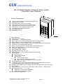
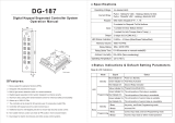
DG-30 Digital Keypad / Proximity Entry system
Operation User's Manual
1. Product Characteristic:
Allows up to 150 Proximity cards / tokens or PIN codes
Tamper Switch Included
Door Reed Switch Input for Anti-Trailing
Fully Programmable via keypad and master code
Extendable from keypad only to proximity controller
Supports 26 or 34-bit Wiegand auxiliary reader
Logical memory to prevent duplication
Non-Volatile Memory
Invalid PIN Lock-out
2. Specifications:
Operating Voltage: 12 Vdc
Current Draw: 60mA Max @12VDC
Input: request-to-exit, time out reed switch contact, auxiliary reader
Relays Electric Current: 2A MAX @30Vdc ;0.4A @ 120Vac
Memory Volume: 150 PIN codes or 100 Proximity cards/tokens and 50 PIN codes
Format: 26 or 34-bit Wiegand hexadecimal.
Relay 1 is controlled by 001~100 user slots(Cards or PIN codes)
Relay 2 is controlled by 101~150 user slots(PIN codes)
PIN codes: 5 digit codes only
Case Material: ABS (UL94V0)
Operating Temperature: -20~+70℃
Ambient Humidity: 5~95% relative humidity non-condensing
Visual Signals:
Red: Power on
Green: Relay activated
Tri-color LED:
Yellow: Program Mode
Red: The slot is registered、Lock-out
Green: This slot may register the card or PIN codes.
Factory Master Code: 12345
Invalid PIN Lock-out: The system will shut down for 60 seconds while 32 codes of
incorrectly Master Codes enrolled or PIN codes attempted.
EPROM: Non-volatile memory, System will retain all programs and codes after a total
loss of power.
Output: Dual relay, N.O./N.C./Com. Output (free voltage contact) 、Tamper switch
Relay Activation Time: (*10、*20)
Strike Time: 1~99 seconds(adjustable)
Strike mode: Access Timer or Latch
Color: Dark gray/ Beige White

Copyright Gianni Industries, Inc. All Rights Reserved.
P-MU-DG30 Ver. A Publish:2004.08.26 Page: 2/ 4
3. The indicator signal chart:
Sound and LED indicator:
Red LED Power on
Green LED Relay activated
Tri-color-Yellow Entering the Program mode
Tri-color-Red Slot position is registered
LED signal
Tri-color-Green Slot position is ready to register
1 Beep
Slot position is ready to register、Effective card( PIN
codes)、Exit from the Program mode
2 Beeps Entering the Program mode
3 Beeps
Slot position is registered 、Data computing error 、 other
operation mistakes、 duplicate card
Sound signal
5 Beeps
Master Code reset to Factory (12345)
Factory Parameter list:
Format 26 bits
Card register None
Master Codes 12345 (5 digits)
Strike Time 1 seconds
Pressed key delay time (Time Out) 5 seconds
Program mode delay time 60 seconds
Invalid PIN Lock-out time 60 seconds
4. Operation Instruction:
Enter Program Mode:
1. Compose twice the master code (Factory master is 「12345」)
→ 2 beeps and the Yellow LED will light up
→ you are now in the "programming mode".
2. Note: After 60 seconds if you have not entered any codes or data, the system will
automatically exit from the programming mode. After 6 wrong attempts at the master
code the lockout facility will operate.
Exiting from the program mode:
1. Press「#」 to exit from the programming mode.
2. Note: After 60 seconds if you have not entered any codes or data, the system will
automatically exit from the programming mode. After 6 wrong attempts at the master
code the lockout facility will operate.
Selecting The User Format
Enter the Programming mode, Press「*30」
Followed By「01」:This will set the system to be used as :Wiegand 26-bit;Slots
001~100 for cards/tokens and slots 01~150 for PIN codes
OR
Followed By 「02」:This will set the system to be used as : Wiegand 34-bit, Slots
001~100 for cards/tokens and slots 01~150 for PIN codes
OR

Copyright Gianni Industries, Inc. All Rights Reserved.
P-MU-DG30 Ver. A Publish:2004.08.26 Page: 3/ 4
Followed By 「03」:This will set the system to be used as : Slots 001~150 for PIN
codes only
Note: When system format has the change, there’s a possibility the card stored would be
invalid. Please reset the system and input all cards /tokens.
Add card and deletion
Enter the Programming mode, Enter the slot position code 「001~100」
A.
Green light comes on: This slot position is ready to register the card
1. Present card in front of the readerÆYellow LED blinks (beep) Æ enrolled
completed Æ(repeat)
2. Present card in front of the readerÆ (3 audible beeps) another card has already
been input (duplicate card).
B.
Red light comes on: This slot already has a code registered
1. Press「**」(deletion) Æ Green light Æ Enter the slot position code again
ÆPresent the card in front of the reader Æ﹝same as Step “A”﹞
2. Enter another slot card position
Add PIN codes and deletion
Enter the Programming mode, Enter the slot position code 「101~150」
A. Green light comes on: This slot position code may register the PIN codes
Input 5 digit PIN codes ÆYellow LED blinks (beep) Æ enrolled Æ(repeat)
B.
Red light comes on: This slot position code is registered
1. Press「**」(deletion) Æ Green light Æ Press the slot position code again Æ
Input 5 digit PIN codes Æ﹝same as Step “A”﹞
2. Enter another slot card position
Note 1: The codes"12345" or master code are not be used for PIN code.
Note 2: PIN codes operate open door:「???????????*****#」
「???….」random codes,「*****」5 digit PIN codes,「#」Enter
To Program Relocking Timer
Enter the Programming mode,
A. Relay 1:Press「*10」Followed by the number of seconds the relay should
open→「05」=5 seconds(01 ~99 = seconds)→(beep)→enrolled → Press
「#」 to exit from the programming mode, or program other operating.
B. Enter「00」Sets the relay to latching mode.
(Correct code entered opens the relay,
and the relay stays open until the correct code is entered again).
C. Relay 2:Press「*20」Followed by the number of seconds the relay should
open)→「05 =5 seconds (01 ~99 = seconds). →(beep)→enrolled → Press
「#」 to exit from the programming mode, or program other operating.
D. Enter「00」Sets the relay to latching mode.
(Correct code entered opens the relay,
and the relay stays open until the correct code is entered again).
Changing the Master codes:
Enter the Programming mode, Enter「*00」Followed by the new 5 digit master
code→(beep)→enrolled→Enter 「#」 to exit from the programming mode, or
program other operating.

Copyright Gianni Industries, Inc. All Rights Reserved.
P-MU-DG30 Ver. A Publish:2004.08.26 Page: 4/ 4
Reset to Factory
Master Code reset to Factory 「12345」
Insert the jumper RES1Æ 1-2 positionÆ5 audible beepsÆReset successfulÆ Return
Insert the jumper to 2-3 position
Remove all stored information
Insert the jumper RES1Æ 1-2 positionÆ5 audible beepsÆ Master Code reset to
Factory 「12345」Æ after 5 secondsÆ5 audible beepsÆ Remove all stored
information Æ Return Insert the jumper to 2-3 position.
Note: If you only wish to reset the Master Code to the Factory default, remove the
jumper after exactly 5 audible beeps, otherwise all cards / codes will be deleted.
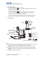
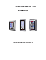
5. Wiring diagram:
123
+12V
GND
DATA
CLK
BUZZER
+5V
A
uxiliary Reader
(Wiegand 26 or
34-bit Format)
Auxiliary Reader
(Data/CLK Format)
To follow the
precedent of
Group 1 contacts
T
a
m
p
e
r
s
w
i
t
c
h
c
o
n
t
a
c
t
o
u
t
p
u
t
(
f
r
e
e
v
o
l
t
a
g
e
c
o
n
t
a
c
t
)
Tamper
Switch
Push Button
FAIL-SAFE
LOCKING DEVICE
Power Supply
Re-set of all
system parameter
Contact door reed switch
This reed switch is used
to reset the re-locking time
to 0 second when the door is moved.
(Using N.O. contact in case of door closed,
changeover to N.C. When door is moved)
Note:
DG-30 controller and auxiliary reader distance must not exceed 20 meters; the data will
not transmit beyond this. The suggested wire gauge is #22~26 AWG.
Using a Linear supply power recommended, to prevent power reduction at the card
reader.
The varistor or diode must be connected across the lock terminal (electromagnet...)
operated by the device. The vartistor controls the overload produced by the strike coil
(EMP).
Egresses switch should be N.O. type.
-
 1
1
-
 2
2
-
 3
3
-
 4
4


Gianni Industries DG-30 User manual
- Category
- Access control readers
- Type
- User manual
Ask a question and I''ll find the answer in the document
Finding information in a document is now easier with AI
Related papers
-
GEM DG-101 User manual
-
Gianni Industries DG-200 Installation guide
-
 Gianni DG-187 Operating instructions
-
-
Gianni Industries DG-120 Installation guide
-
-
-
-
-

Other documents
-
 ANXELL DG-30 Operation User's Manual
-
-
 Gianni DG-160 Operating instructions
-
 Alarm Controls Corporation KP-100 Operating Instructions Manual
-
-
 SIB Standalone Keypad Access Control User manual
-
-
Paxton OEM Plastic Reader Keypad Owner's manual
-
-
Mace Ins-50012-MS User manual


