Page is loading ...

1
740DM - 20
6/22
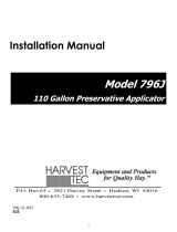
OWNER’S MANUAL
Model 740DM
Dye Sprayer Marking System
Forage Harvester

2
Harvest Tec 740DM Table of Contents
Page
Introduction & Tools Needed
2
Installation of Dye Sprayer Tank & Plumbing
3-8
Installation of Mounting Bracket & Tank – Large Square Balers
3
System Wiring
4
Installation of Plumbing and Wiring
5-6
Plumbing Diagram
7
Common Questions & Troubleshooting
7
Maintenance
7
Filling Tank & First Time & Annual Start UP
8
1. Filling the Tank
8
2. First Time & Annual Start up
8
Operation Instructions Automatic or Manual Mode
8
Pin Outs
9
Parts Breakdown
10
Warranty
18
Introduction
Congratulations on purchasing a Harvest Tec Dye Sprayer Marking System. When attached to a 700 Series
Automatic Applicator or 700 Series Moisture Only kit for any large square baler, will allow you to visibly mark
the wet areas on your bales. The system includes the tank, pump, plumbing mounting hardware and necessary
cables. There is a parts breakdown in the back of the manual to reference if replacement parts are needed. All
replacement parts and dye will be ordered through your local equipment dealer.
Tools Needed
Standard wrench set
Hammer
Straight edge
Standard socket set
Tape measure
Metal drilling and cutting tools
Center punch
Marker

3
Installation of Dye Sprayer Tank & Plumbing
Installation of Mounting Bracket & Tank – Large Squares
Locate the tank and mounting bracket assembly. Looking at Figures 1, 2 & 3 decide which of these mounting
locations will be the most convenient and work the best for the user.
a. Once tank location is decided, mark the mounting holes and drill out using 3/8” bit.
b. Fasten the mounting bracket to the baler using the 5/16” hardware provided in the kit.
Figure 2
New Holland 590,595, BB940-960A
Case LBX331-432
Figure 3
New Holland BB9060-9080
Case LB & New Holland BB Models
Figure 1
Common Hesston, Massey Ferguson,
Challenger Balers

4
System Wiring
1. Locate the wiring harness (006-765IDM) supplied in the 740 dye Sprayer Marking Kit. Attached
12 pin plug into module mounted on the metal frame of the dye marker.
2. Plug uncapped triangle plug into plug on metal frame.
3. Run Dye Marking harness down to main applicator harness (006-765B or 006-765B2) and
attach it to one of the two CAN plugs.
System Wiring Diagram
Hay Indicators
006-7502(E / R)
Solenoids
002-2203F
Flow Meter
006-4724A
ISO Communication Module
(ICM) 030-6672C
Power Harness on Tractor
006-765IC
700 ISO Pump Module
006-7671LS
Power Harness on Tractor
006-765B
End of Bale Sensor
006-7400
Moisture Harness
006-7303EM2
Key Power Harness
006-765CPH
Optional Harvest Tec
Display Harness
006-765GH
Baler Integration Harness
006-765VA
Active Terminator from Baler
Optional
Hay Indicator Harness
006-7503H
Solenoid Harness
006-3650-S1
Star Wheels
030-4642 (U/UE)
Dye Marker Harness
006-765IDM

5
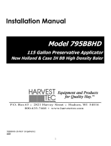
Installation of Plumbing
To most effectively mark the wet spots in any bale, Harvest Tec recommends that the nozzles are
mounted directly above or below the Star Wheels. To get the best spray pattern focused directly on
the wet spot of the bale the nozzles will need to be approximately 1” above the bale that is being
marked. A small notch may need to be cut to increase surface area of the bale being marked.
1. Once you have the tank and mounting bracket securely fastened to the baler, locate parts A, B,
C, D & E pictured below in Figure 1 or 2. Assemble in the following order: (A) Elbow | (B) nozzle
holder | (C) check valve | (D) reducing bushing | (E) tip as pictured below.
*****Note: All parts should be thread taped*****
2. Once the nozzle holders are fastened to the balers, route the 3/8” hose to the tips. Make sure to
fasten the hose securely but avoid pinching the lines. (Plumbing Diagram pictured in Figure 7)
*****Keep from routing the hose in the way of moving parts on the baler*****
3. Attach drain hose top hose barb fitting at bottom of tank. Run hose to a secure point and attach
valve assembly.
J
Check Valve
004-1207V
A
Elbow
003-SE14F
C
Brass Tip
004-TX-5
F
Straight Fitting
003-A1418
G
Quick Connect
004-1207H
H
Rubber Gasket
004-1207W
I
Tip Screen
004-1203-100
E
Nozzle Holder
001-4216
B
Nozzle Body
004-4722
D
Nozzle Cap
004-4723

6
Installation of Plumbing and Wiring
4. Install the tip and nozzle holder assemblies in the suggested locations pictured shown below.
Use the 1/4” hardware provided to do so.
a. Make sure that the tip assemblies (A) are mounted in line with the star wheels (B) so that
the system is marking the wet spots of the bale.
Example A
A
B
A
B
Example B

7
Plumbing Diagram
Common Question
1. Is the marking dye safe for livestock consumption?
The DSM uses red-colored, food-grade dye and is safe for all livestock.
2. How do I bleed the air out of the lines properly?
Remove the tips from the check valves that they’re threaded into and press the prime button on
the dye marker until the air is pushed out of the lines.
Troubleshooting
Problem
Possible Cause
Solution
The tips are not spraying Dye
1. The system is out of dye.
2. There is air in the lines,
preventing a steady mist
coming from the tips.
3. Damaged/pinched hose.
4. Tip is plugged.
5. Set point is set too high
1. Check the tank for solution. If the tank
is empty, refill and bleed air from lines.
2. Remove the tips from the check valves
and using the priming button bleed the
air out of the lines.
3. Inspect all the hose making sure the
lines are damaged or pinched.
4. Removed the tip from the bushing and
inspect, clean is necessary.
5. Lower the set point level at which the
user would like to have the bales
marked at.
Maintenance
1. For winter storage, drain all of the liquid out of the lines and tank and pump.
Tank
005-9019
Pump
007-4120LF
3/8” Hose
002-9003AS
Hose Barb Tee
003-T3838
Brass Tip
004-TX-5
Drain Valve
002-2216

8
Filling Tank & First Time and Annual Startup
1. Filling the Tank
A. Remove the tank lid from the 3 gallon tank. Make sure the tank is clean and completely
empty. Mix the Dye (009-0800) with warm water inside the Dye bottle. Make sure that the
bottle is shaken vigorously so that the dye completely dissolves. Once the solution is mixed,
add it to the 3 gallon tank and fill the tank with water.
2. First Time and Annual Startup
A. Once the tank has been filled the plumbing lines will need to be primed. With the system
turned on and in a paused mode, hold the priming button until all the air is flushed out of the
lines and there is a steady stream of liquid coming from each of the tips.
***NOTE: The system needs to be primed every time the system has run out of dye***
B. You can adjust the moisture content level at which you would like the system to mark the ‘Wet
Flakes’ in the bale being made. This can be done by entering ‘Setup’ followed by moisture
setup, then adjust Set Point.
Operating Instructions Automatic Mode or Manual Mode
Auto & Manual mode will automatically mark bales with dye if the moisture dye marking system is
turned on and moisture content sensed by the star wheels is above the moisture ‘Set Point’ level that
was set by the operator.
1. The moisture sensed by the star wheels is indicated below. See page 9 for set-up instructions.
Moisture form
star wheels
Dye marker
Set Point

9
Pin Outs
Integrated Dye Marker Module (IDM) on harness 006-765IDM
(Deutsch Plug Number: DTM06-12SA)
ISOBUS Plug on harness 006-765IDM
(Deutsch Plug Number: DT04-4P)
End of Bale Sensor Plug on Harness 006-765IDM
(Deutsch Plug Number: DT06-3S)
Prime Switch Plug on Harness 006-765IDM
(Deutsch Plug Number: DT06-3S)
Pin 1
Red
+12V from ECU
Pin 2
Red/Black
+12V, EOB
Pin 3
Black/White
Ground, EOB
Pin 4
-
-
Pin 5
-
-
Pin 6
Purple
Signal, EOB
Pin 7
Green
ISO CAN Lo
Pin 8
Yellow
ISO CAN Hi
Pin 9
Red/White
+12 DSM
Pin 10
Black/White
Ground DSM
Pin 11
Blue
Prime, DSM
Pin 12
Black
Ground from ECU
Pin 1
Red
+12V from ECU
Pin 2
Yellow
ISO CAN Hi
Pin 3
Green
ISO CAN Lo
Pin 4
Black
Ground from ECU
Pin 1
Red/Black
+12V to End of Bale Sensors
Pin 2
Black/White
Ground to End of Bale Sensors
Pin 3
Purple
Signal
Pin 1
Orange/White
+12V to Pump
Pin 2
Black/White
Ground to Pump
Pin 3
Blue
Prime
1
3
v
2
v
4
v
7
8
9
10
11
12
1
2
3
4
5
6
1
3
2

10
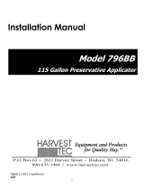
Parts Breakdown
Ref
Description
Part#
Qty
Ref
Description
Part#
Qty
1
Tank
005-9019
1
12
3/4x1/4” Reducer
003-RB3414
1
2
DSM Mounting Bracket
001-2500
1
13
1/4x1/4” Nipple
003-M1414
1
3
Tank Cap
005-9022C
1
14
1/4x3/8” Fitting
003-A1438
2
4
Dye Marker Control
006-2472DM
1
15
1/4" FPT Tee
003-TT14
1
5
DSM Wire Harness
006-765IDM
1
16
1/4x3/8” Elbow
003-EL1438
1
6
Remote Push Switch
006-2850
1
17
SLV Bottle Valve
002-2216
1
7
DM Pump Switch
006-765IDM2
1
18
Male Quick Connect
004-4710
1
8
Hose Clamp
002-9002
10
19
Rubber Gasket
004-1207W
2
9
3/8” Barbed Tee
003-T3838
1
20
Shut-Off Cap
004-1207F
1
10
3/8” EDPM Hose
002-9003AS
26’
11
DSM Pump
007-4120LF
1
NP
Tank Cap Gasket
005-9022CG
1
Ref
Description
Part#
Qty
21
Nozzle Holder
001-4216
2
22
Straight Fitting
003-A1438
2
23
Quick Connect
004-1207H
2
19
Rubber Gasket
004-1207W
2
25
Tip Screen
004-1203-100
2
26
Check Valve
004-1207V
2
27
Street Elbow
003-SE14F
2
28
Nozzle Body
004-4722
2
29
Brass Tip
004-TX-5
2
30
Nozzle Cap
004-4723
2
5
1
2
4
3
21
23
22
19
27
28
26
29
25
30
6
7
8
9
10
11
12
13
14
15
16
14
17
18
19
20

11
Harvest Tec LLC. Warranty and Liability Agreement
Harvest Tec, LLC. will repair or replace components that are found to be defective within 12 months from the
date of manufacture. Under no circumstances does this warranty cover any components which in the opinion
of Harvest Tec, LLC. have been subjected to negligent use, misuse, alteration, accident, or if repairs have
been made with parts other than those manufactured and obtainable from Harvest Tec, LLC.
Our obligation under this warranty is limited to repairing or replacing free of charge to the original purchaser
any part that in our judgment shows evidence of defective or improper workmanship, provided the part is
returned to Harvest Tec, LLC. within 30 days of the failure. If it is determined that a non-Harvest Tec branded
hay preservative has been used inside the Harvest Tec applicator system where the failure occurred, then
Harvest Tec reserves the right to deny the warranty request at their discretion. Parts must be returned through
the selling dealer and distributor, transportation charges prepaid.
This warranty shall not be interpreted to render Harvest Tec, LLC. liable for injury or damages of any kind,
direct, consequential, or contingent, to persons or property. Furthermore, this warranty does not extend to
loss of crop, losses caused by delays or any expense prospective profits or for any other reason. Harvest
Tec, LLC. shall not be liable for any recovery greater in amount than the cost or repair of defects in
workmanship.
There are no warranties, either expressed or implied, of merchantability or fitness for particular purpose
intended or fitness for any other reason.
This warranty cannot guarantee that existing conditions beyond the control of Harvest Tec, LLC. will not affect
our ability to obtain materials or manufacture necessary replacement parts.
Harvest Tec, LLC. reserves the right to make design changes, improve design, or change specifications, at
any time without any contingent obligation to purchasers of machines and parts previously sold.
Revised 6/22

12
HARVEST TEC, LLC.
P.O. BOX 63
2821 HARVEY STREET
HUDSON, WI 54016
PHONE: 715-386-9100
1-800-635-7468
FAX: 715-381-1792
Email: info@harvesttec.com
/