Page is loading ...


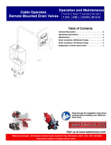
Table of Contents
Safety 4
Safety Precautions 4
Introduction 5
Using this Document 5
Viewing the Document Electronically 5
Printing the Document 5
Additional Documentation 5
Symbols 5
Product Overview 6
Congurations 6
Individually Installed Components 7
Panel Switch with Single Priming Pump
Overview 8
Auto-Prime Switch 8
Standard Push Button Switch 8
Oversized Push Button Switch 8
Multiple Priming Valve System Overview 9
Dual Priming Pump System Overview 10
Auto-Prime Switch 12
Standard Push Button Switch 14
Oversize Push Button Switch 15
Priming Pump—12V 16
Priming Pump—24V 17
Pressure Switch 18
Priming Valve Solenoid 19
Priming Valve 20
Priming Pump Cable 21
Priming Valve Solenoid Extension Cable 22
Extension Cable—Optional 23
Pressure Switch Extension Cable 24
Installation 26
Installation Overview 26
Determining Cable and Wire Routing 26
Preparing for the Installation 26
Optional Equipment 26
Hose and Tubing Requirements 26
Tubing 26
Hose 26
Determining the Installation Requirements 27
Installation Requirements 27
Auto-Prime Switch Cutout Dimensions 28
Standard Push Button Switch Dimensions 29
Oversized Push Button Switch Dimensions 30
Priming Pump Dimensions 31
Panel Cutout and Mounting Holes 32
Installing the Auto-Prime Switch 33
Positioning the Switch 33
Mounting the Enclosure 34
Mounting the Panel 35
Installing the Standard Push Button Switch 36
Installing the Oversized Push Button Switch 37
Installing the Priming Pump 38
Installing the Priming Valve 39
Installing the Pressure Switch 40
Installing the Priming Valve Solenoid 41
Connecting to Apparatus Power 42
Priming Pump—12V 42
Priming Pump—24V 43
Dual Priming Pumps—12V 44
Dual Priming Pumps—24V 45
Connecting the Extension Cable 46
Priming Pump—12V 46
Priming Pump—24V 47
Dual Priming Pumps—12V 48
Dual Priming Pumps—24V 49
Connecting the Priming Components 50
Priming Pump and Priming Valve 50
Multiple Priming Valves 51
Dual Priming Pumps 52
Auto-Prime Push Button Switch 53
Standard Push Button Switch 54
Oversized Push Button Switch 55
Multiple Priming Valves 56
Multiple Priming Pumps 57
Operation 58
Priming the Pump—Auto-Prime Switch 58
Priming the Pump—Manual-Prime Switch 59
Maintenance 60
Maintenance Schedule 60
Vacuum Testing 60
Priming Valve 60
Priming Tank 60
Priming Pump 60

4 | 62
Safety Precautions
• Read and understand all the associated documentation before you begin the
installation.
• Read and understand all the notices and safety precautions.
• Be aware that these instructions are only guidelines and are not meant to be
definitive. Contact Waterous when you have questions about installing,
operating, or maintaining the equipment.
• Do not install the equipment if you are not familiar with the tools and skills
needed to safely perform the required procedures—proper installation is the
responsibility of the purchaser.
• Do not operate the equipment when safety guards are removed.
• Do not modify the equipment.
• Regularly check for leaks, worn, or deteriorated parts.
NOTICE
Before Operation
• Read and understand all
the instructions provided.
• Check all fluid levels
and replenish if necessary.
• Remove all shipping plugs
and install the operation
plugs or caps.
NOTICE
• Do not prime the pump for
more than 1 minute.
• Operating the priming pump
more than 1 minute can
damage the motor or the
motor solenoid.
Priming Pump Damage

5 | 62
Use this document to install and operate your Waterous equipment. Understand
the following conditions before continuing with the document:
• The instructions may refer to options or equipment that you may not have
purchased with your system.
• The illustrations in this document are intended to convey concepts. Do not
use the illustrations to determine physical attributes, placement, or
proportion.
• Understand that your application may require additional steps, that are not
described in the illustrations or instructions, to perform the installation.
• Any equipment described in this document is intended to be installed by a
person or persons with the necessary skills and knowledge to perform the
installation.
• Any equipment described in this document is intended to be operated by a
person or persons with the basic knowledge of operating similar equipment.
• Do not install the equipment if you are not familiar with the tools and skills
needed to safely perform required procedures—proper installation is the
responsibility of the purchaser.
This document is divided into the following sections:
This section describes general precautions and alert symbols that are in this
document.
This section is an overview of the document.
This section describes the components that make-up the system.
This section describes the installation and initial setup procedures.
This section describes the equipment operation.
This section describes maintaining the equipment.
Using this Document
Use the guidelines below when viewing this document.
Viewing the Document Electronically
• View this document in landscape orientation.
• Use the table of contents to navigate directly to that section.
• Text with this appearance is linked to a reference.
Printing the Document
• The document is viewed the best when printed in color.
• The print on both sides and flip on long edge features can provide the
best results.
• Use a 3-ring binder to store the document.
Additional Documentation
Additional documentation is available through the MyWaterous login at
Waterousco.com. Use your serial number to gain access to the service parts
list associated with your system. Dimensional drawings are available through
the Waterous Service department.
Symbols
Symbols are used to illustrate additional tools or operations that are required to
complete the instructions.
Drill—This symbol tells you to drill the mounting holes in the
apparatus.
Jig saw—This symbol tells you to make a cutout in the apparatus.
Torque to specification—This symbol tells you to torque the
hardware to the specified value.

6 | 62
When ordered together with the pump and transmission, depending on the configuration, the priming pump (VPO), priming valve (VAP), hose, and panel cable are
installed at the factory. Otherwise, components are shipped loose and installed individually.
Factory Mounted Priming System Individually Installed Components

7 | 62
Individually Installed Components
Individually installed components in your application may include the following items.
Auto-Prime Switch Standard Push Button Switch Oversized Push Button Switch Switch Cable—70 inches Panel Plate
Priming Pump Outlet Muffler Priming Hose Kit—48 inches Additional Fittings Dual Priming Pump Jumper
Wire—18 inches
Safe-Prime™ Lubrication
System

8 | 62
Panel Switch with Single Priming Pump Overview
There are 3 panel switch options available that operate the priming system.
Auto-Prime Switch
Auto-prime with integrated push-to-prime operation.
Standard Push Button Switch
Standard push-to-prime switch.
Oversized Push Button Switch
Larger button push-to-prime switch preferred by
some operators.


Notes


13 | 62
Auto-Prime Switch
FeatureFeature DescriptionDescription
1Mounting holes—Panel This mounts the switch to the apparatus.
2Button This operates the priming function.
3Enclosure This contains the electronic components.
4Mounting holes—Enclosure This mounts the enclosure to the apparatus.
5 Pressure switch connector This connects to the pressure switch—DT06-2S.
6 Priming valve solenoid connector This connects to the priming valve solenoid when applicable—DTM04-2P.
7Priming pump connector This connects to the priming pump switch cable—DT04-4P.
8Power connector This connects to apparatus power or to the previous switch—DT06-4S.

14 | 62
Standard Push Button Switch
This allows you to manually prime the pump.
543
1
2
FeatureFeature DescriptionDescription
1Mounting holes This mounts the switch to the apparatus.
2Prime button This activates the priming operation.
3Additional panel connector This connects to the next switch, when applicable—DT06-4S, Pin 1=12 V, Pin 2=Ground.
4 Priming valve solenoid connector This connects to the priming valve solenoid, when applicable—DTM04-2P.
5Priming pump connector This connects to the priming pump switch cable—DT04-4P.

15 | 62
Oversize Push Button Switch
This allows you to manually prime the pump.
3
1
2
FeatureFeature DescriptionDescription
1Mounting holes This mounts the switch to the apparatus.
2Prime button This activates the priming operation.
3Priming pump connector This connects to the priming pump switch cable—DT04-4P.

16 | 62
Priming Pump—12V
This generates the vacuum that primes the pump.
1
2
3
4
5
6
8
74
FeatureFeature DescriptionDescription
1Power terminal This is connected to the red extension cable wire.
2Signal terminal This is connected to the white extension cable wire.
3Ground terminal This is connected to the black extension cable wire.
4Mounting holes This mounts the priming pump to the transmission bracket.
5Inlet This connects to the hose fitting—3/4-inch NPT.
6 Priming lubricant port This connects to the optional prime-lubricant tank—1/8-inch NPT.
7Outlet This exhausts the evacuated air—3/4-inch NPT.
8Solenoid This engages the priming pump. Note: The solenoid does not incorporate flyback voltage protection.

17 | 62
Priming Pump—24V
This generates the vacuum that primes the pump.
1
2
3
4
5
6
74
8
FeatureFeature DescriptionDescription
1Power terminal This is connected to the red extension cable wire.
2Signal terminal This is connected to the white extension cable wire.
3Ground terminal This is connected to the black extension cable wire—the 24V incorporates an additional jumper wire.
4Mounting holes This mounts the priming pump to the transmission bracket.
5Inlet This connects to the hose fitting—3/4-inch NPT.
6 Priming lubricant port This connects to the optional prime-lubricant tank—1/8-inch NPT.
7Outlet This exhausts the evacuated air—3/4-inch NPT.
8Solenoid This engages the priming pump. Note: The solenoid does not include flyback voltage protection.

18 | 62
Pressure Switch
This facilitates the auto-prime operation.
1
2
FeatureFeature DescriptionDescription
1Connector This connects to the auto-prime switch—DT04-2P, cable length: 10 inches (254 mm).
2 Switch housing This threads into the fire-pump intake—1/4 NPT.

19 | 62
Priming Valve Solenoid
This allows multiple priming valves to be isolated from each other. Only used with single priming pump/multiple priming valve applications.
2
1
3
FeatureFeature DescriptionDescription
1Connector This connects to the switch—DTM06-2S, cable length: 6.5 inches (165 mm).
2Vent port This allows vacuum to be pulled from the top of diaphragm.
3Mounting holes This mounts the solenoid to the priming valve.

20 | 62
Priming Valve
This allows air to evacuate the fire pump.
1
4
5
3
2
6
FeatureFeature DescriptionDescription
1Mounting hardware This mounts the priming valve to the fire-pump intake or priming valve base.
2Priming valve top This is the top of the priming valve.
3Priming valve outlet This connects to the priming pump.
4Priming valve inlet plug This plugs the unused inlets.
5Priming valve intake This draws the vacuum from the pump.
6 Priming valve base This is an alternative mount for certain fire pump models.
/