ESAB MA44 Aristo User manual
- Category
- Welding System
- Type
- User manual
This manual is also suitable for
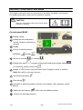
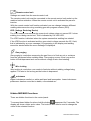
ESAB MA44 Aristo is a versatile welding control panel that offers precise control over MIG/MAG and MMA welding processes. With its user-friendly interface, you can easily set and monitor welding parameters such as voltage, wire feed speed, and welding current. The MA44 also features advanced functions like QSet and synergic welding, making it ideal for both basic and complex welding tasks.
ESAB MA44 Aristo is a versatile welding control panel that offers precise control over MIG/MAG and MMA welding processes. With its user-friendly interface, you can easily set and monitor welding parameters such as voltage, wire feed speed, and welding current. The MA44 also features advanced functions like QSet and synergic welding, making it ideal for both basic and complex welding tasks.


-
 1
1
-
 2
2
-
 3
3
-
 4
4
-
 5
5
-
 6
6
-
 7
7
-
 8
8
-
 9
9
-
 10
10
-
 11
11
-
 12
12
-
 13
13
-
 14
14
-
 15
15
-
 16
16
-
 17
17
-
 18
18
-
 19
19
-
 20
20
-
 21
21
-
 22
22


ESAB MA44 Aristo User manual
- Category
- Welding System
- Type
- User manual
- This manual is also suitable for
ESAB MA44 Aristo is a versatile welding control panel that offers precise control over MIG/MAG and MMA welding processes. With its user-friendly interface, you can easily set and monitor welding parameters such as voltage, wire feed speed, and welding current. The MA44 also features advanced functions like QSet and synergic welding, making it ideal for both basic and complex welding tasks.
Ask a question and I''ll find the answer in the document
Finding information in a document is now easier with AI
Related papers
-
ESAB ESAT ESAB Software Administration Tool Software version 1.3 User manual
-
-
-
-
-
ESAB MA24 Origo™ User manual
-
-
-
ESAB MA25 Pulse User manual
-