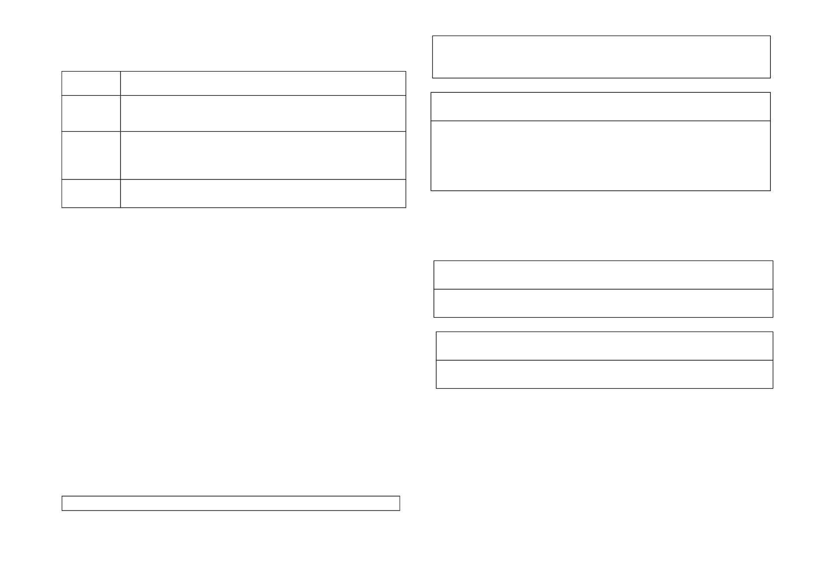
Z-Wave z-WAVE PAD07 In Wall Smart Dimmer User manual

Type
User manual

This manual is also suitable for

Z-Wave PAD07 In Wall Smart Dimmer is a wireless dimmer that enables you to control the brightness of your dimmable LED bulbs and other compatible lights using Z-Wave technology. You can turn lights on/off by pressing the button briefly or adjust brightness by long pressing. The dimmer also features built-in thermal cut-off fuse protection for added safety and supports association with other Z-Wave devices for creating smart scenes and automations.

Z-Wave PAD07 In Wall Smart Dimmer is a wireless dimmer that enables you to control the brightness of your dimmable LED bulbs and other compatible lights using Z-Wave technology. You can turn lights on/off by pressing the button briefly or adjust brightness by long pressing. The dimmer also features built-in thermal cut-off fuse protection for added safety and supports association with other Z-Wave devices for creating smart scenes and automations.

PAD07 In Wall Smart Dimmer
Action Button
(Power/Include/Exclude)
Warning: Do not use Non-Dimmable LED lamps.
PAD07 is a security enabled wireless dimmer, based on Z-Wave
Plus technology. Z-Wave Plus
TM
enabled devices displaying the Z-
Wave Plus
TM
logo can also be used with it regardless of the manu-
facturer, and can also be used in other manufacturers Z-Wave
TM
enabled networks. You can On/Off the light by pressing the button
briefly, or a long pressing to control the brightness of dimmable
light bulb.
This dimmer is a transceiver which is a security enabled device
which based on Z-Wave Plus technology, and it is fully compatible
with any Z-Wave
TM
enabled network. Since PAD07 supports Se-
curity Command Class, it can learn with a Secured enabled con-
troller to fully utilize the device. Its functionality and supported
command classes is identical when included as a secure and non-
secure device.
Specification
Rated 100-240 Vac 50Hz-60Hz 1A
Output Load Maximum 0.9A (100-240 Vac)
Fuse Information
Built-in High Breaking Capacity Current Fuse Protection.
Rated: 2A; 250V
Built-in Thermal Cut-off Fuses Protection.
Rated Temperature: 125°C; Rated: 2A 250V
Maximum Watts 200W (13W x 15 pieces) (Dimmable LED bulbs)
(230Vac)
Maximum Watts 100W (6.5W x 15 pieces)or (10W x 10 pieces) (Dimmable
LED bulbs); (120Vac)
Max. load (watts) Maximum: 15 pieces (Dimmable LED bulbs)
Operating Temperature 0°C to 40°C
Humidity Up to 85% max
Storage Temperature -20°C - 60°C
Location Indoor use only
Frequency Range
868.40MHz, 869.85MHz EU
908.4MHz, 916.0MHz US,
922.5MHz, 923.9MHz, 926.3MHz (JP)
920.9MHz, 921.7MHz, 923.1MHz (TW/KR/Thai/SG)
RF Maximum Power +5dBm
Transmission Range Up to 40m indoors or up to 100m outdoors (depending on
building materials)
OTA support
FCC ID RHHPAD07
Dimensions 47.5 x 39 x16 mm
Wire 0.75mm² ; 18AWG
Specifications are subject to change and improvement without notice
.
1
Troubleshooting
Symptom Cause of Failure Recommendation
The dimmer does not
work and LED off
1.
The dimmer does not
connect to electrical wire
properly.
2.
Dimmer is broken.
1.
Check the power
connections.
2.
Do not open the dimmer
and send it back to
distributor.
The dimmer LED
illuminating, but cannot
control the ON/OFF
state of the load
attached
Check if the load connected to
the dimmer has its own
ON/OFF switch
Set the ON/OFF switch of the
load attached
to ON
The dimmer LED
illuminating, but the
detector cannot control
the Switch
1. Not carry out association
2. Same frequency
interference
1. Carry out association
2. Wait for a while to re-try
Installation
Fig 1. Assembling & Wiring
IMPORTANT
Installation must be performed by skilled technicians who are
informed about the standards and technical requirements of the
appliance and its proper installation.
Check your local codes as they apply to your situation. If the
house wiring is of aluminum, consult with an electrician about
proper wiring methods.
Before proceeding with the installation, TURN OFF THE POWER
TO THE LIGHTING CIRCUIT AT THE CIRCUIT BREAKER OR
FUSE BOX TO AVOID ELECTRICAL SHOCK.
For Instruction to http://
www.philio-tech.com
Danger
Danger of Electrocution!
All works on the device may be performed only by a qualified and
licensed electrician. Observe national regulations. Any works
introducing changes into the configuration must be always
performed with disconnected voltage.
Choosing a Suitable Location
1.
Do NOT place the module/device direct under sunlight, in a
2
humid place or in any location where they may contact
moisture, dirt, dust.
2.
Do NOT place the module/device where exists combustible
substance or any source of heat, fires, radiators, boiler etc.
3.
When the module/device be used, the module/device might
get warm. This is a normal condition.
Adding to Z-WaveTM
Network
In the front casing, there is an on/off button (also an include button) with LED
indicator below which is used to dim on and off or carries out inclusion, exclu-
sion, reset or association. When first power applied, its LED flashes on and off
alternately and repeatedly at 0.5 second intervals. It implies that it has not been
assigned a node ID and start auto inclusion.
Auto Inclusion
The function of auto inclusion will be executed as long as the dimmer does not
have Node ID and just connect the switch to main power.
Note: Auto inclusion timeout is 2 minute during which the node information of
explorer frame will be emitted once every several seconds. Unlike “inclusion”
function as shown in the table below, the execution of auto inclusion is free
from pressing the On/Off button on the dimmer.
The table below lists an operation summary of basic Z-Wave functions. Please
refer to the instructions for your Z-Wave
TM
Certificated Primary Controller to ac-
cess the Setup function, and to Add/Remove/Reset/associate devices
Function Description Annotation
No node ID The Z-Wave Controller does not allocate
a node ID to the Switch.
LED 2-second on, 2-
second off
Add
(Inclusion)
1. Put your Z-Wave controller into
inclusion mode by following the
instructions provided by the
controller manufacturer.
2. Pressing Include button of PAD07
three times within 2 seconds will
enter inclusion mode.
Remove
(Exclusion)
1. Put your Z-Wave controller into
exclusion mode by following the
instructions provided by the
controller manufacturer.
2. Pressing Include button of PAD07
three times within 2 seconds will
enter exclusion mode.
3. Node ID has been excluded. 0.5s On, 0.5s Off (Enter
auto inclusion)
Reset 1. Pressing Include button of PAD07
three times within 2 seconds will
enter inclusion mode.
Use this procedure only
in
the event that the primary
controller is lost or
otherwise inoperable.
2. Within 1 second, press Include
button of PAD07 again for 5
seconds.
3. IDs are excluded. 0.5s On, 0.5s Off (Enter
auto inclusion)
Association 1. The PAD07 is an always listening
Z-Wave device, so associations may
be added or removed by a controller
at any time.
Or If your controller requires to have
the PAD07 send a 'node information
frame' or NIF for associations, then
pressing the On/Off button three
times within 2 seconds will cause
the PAD07 to send its NIF.
2. There are two groups for the dimmer.
Adding a node ID allocated by Z-Wave Controller means inclusion. Removing a
node ID allocated by Z-Wave Controller means exclusion.
Failed or success in including/excluding the node ID can be viewed from the Z-
Wave Controller.
3
LED Indication
To distinguish what mode the switch is in, view from the LED for identification.
State
Type
LED Indication
Normal Whenever we switch On and off of the PAD07 by On/Off button
or RF command, the LED will lights up when switch on;
whereas LED off when switch off.
No node
ID
Under normal operation, when the Switch has not been
allocated a node ID, the LED flashes on and off alternately at
2-second intervals. By pressing On/Off button, it will stop
flashing temporarily.
Learning When PAD07 is in learning mode, LED flashes on and off al-
ternately and repeatedly at 0.5 second intervals.
Manual dim level control :
To manually switch on the light, press and release the On/Off button or S1/S2
shortly when the light is off. The light will dim from off to the level which was set
before switch off. To manually switch off the light, press and release the On/Off
button or S1/S2 shortly when the light is on. To adjust the dim level, press and
hold the On/Off button or S1/S2 until the desired dim level is achieved, then re-
lease.
Programming
1. Basic Command Class / Multilevel Switch Command Class
The dimmer will respond to BASIC and MULTILEVEL SWITCH commands that
are part of the Z-Wave system. If PAD07 is included as a secured node, it will
only response to the security encapsulation command of BASIC and MULTI-
LEVEL SWITCH.
1-1 BASIC_GET / MULTILEVEL_SWITCH_GET
Upon receipt of the following commands from a Z-Wave Controller, the Switch
will report its dimmer state to the node inquired.
Basic Get Command: [Command Class Basic, Basic Get]
Basic Report Command:
Report OFF: [Command Class Basic, Basic Report, Value = 0]
Report ON:[Command Class Basic, Basic Report, Value = 1~99]
Multilevel Switch Get Command:[Command Class Multilevel Switch,
Multilevel Switch Get]
Multilevel Switch Report Command:
Report OFF:[Command Class Multilevel Switch, Multilevel Switch Re-
port, Value=0]
Report ON:[Command Class Multilevel Switch, Multilevel Switch Re-
port, Value =1~99]
1-2 BASIC_SET / MULTILEVEL_SWITCH _SET
Upon receipt of the following commands from a Z-Wave Controller, the load
attached to the dimmer will turn on or off.
[Command Class Basic, Basic Set, Value = 0] : the load attached to the
dimmer turns off.
[Command Class Basic, Basic Set, Value = 1~99] : the attached load
dim on as the level.
[Command Class Multilevel Switch, Multilevel Switch Set, Value=0,
Duration = 0~255] : the load attached to the dimmer turns off.
[Command Class Multilevel Switch, Multilevel Switch Set, Value
=1~99, Duration = 0~255] : the attached load dim on as the level.
1. Z-Wave’s Groups
The Switch can be set to send reports to associated Z-Wave devices. It sup-
ports one association group with five nodes support for grouping 1. For group 1,
the dimmer will report MULTILEVEL_SWITCH_REPORT, ALARM_REPORT
and DEVICE_RESET_LOCALLY_NOTIFICATION.
2-1 Grouping 1 Lifeline(Maximum 5 nodes)
2-1-1 Device reset locally notification :
When PAD07 is reset manually, it will send a DEVICE_RESET_LOCALLY_
4
NOTIFICATION to the nodes of group 1.
2-1-2 On/Off Event Report
When “on” or “off ” state has been changed, it will send Multilevel Switch Report
to the nodes of Grouping 1.
Multilevel
Switch Report
ON:[Command Class Multilevel Switch, Multilevel Switch Report,
Value =1~99]
OFF:[Command Class Multilevel Switch, Multilevel Switch Report,
Value =0(0x00)]
2-1-3 Overload alarm report
When PAD07 detects the Overload, it will send Alarm Report to Group 1 nodes.
After detecting overload state and sending this alarm report, PAD07 will turn off
the dimmer automatically and lockout the On/Off button and S1/S2. The only
thing to do is unplug PAD07 and reduce the load. Then re-power on PAD07 and
it will work again.
The content of Alarm Report
Alarm report command: [Command_Class_Alarm, Alarm_Report, Alarm Type
= 0x08, Alarm Level = 0xFF]
2-2 Grouping 2 Control_Key1 : (Maximum 5 nodes)
When the On/Off status changes or the dim level is achieved manually, it will
send BASIC_SET command to group 2 nodes to make them unanimous.
Dimmer Off : [Command Class Basic, Basic Set, Value = 0]
Dimmer On : [Command Class Basic, Basic Set, Value = 1~99]
3.
Z-Wave’s Configuration
Configuration
Parameter
Function Size
(Byte)
Value Unit Default Description
1Dimmer Level
Report mode
1 0-1 1 0 : Disable
1 : Enable
2LED indication 1 1-3 1 1: Show dimmer state
mode 2 : Show night mode
3: One flash mode
3External switch
type
1 1-3 1 1 : One switch mode
2 : Two switch mode
3: Up/Down switch
mode
4Restore dimmer
state
1 0-2 1 0 : Dimmer off
1 : Last dimmer state
2 : Dimmer on
3-1 Dimmer level report mode :
Whenever dimmer on/off state changes, it will send MULTILEVEL_SWITCH_
REPORT to the nodes of group1. The default setting is Enable the function.
3-2 LED indication mode :
3-2-1 Show dimmer StateWhen dimmer is on, LED is on. When dimmer is
off, LED is off. The default setting is Show dimmer State.
3-2-2 Show Night modeWhen dimmer is on, LED is off. When dimmer is
off, LED is on.
3-2-3 One flash mode When dimmer on/off state changes, LED will light
on one second and then off.
3-3 External switch type
3-3-1 One switch modeOnly S1 can dim up the light bulb to brightest level,
then dim down to darkest level, and so on…
3-3-2 Two switch modeS1 and S2 can dim up the light bulb to brightest
level, then dim down to darkest level, and so on…
3-3-3 Up/Down switch modeS1 can only dim up the light bulb to brightest
level, and S2 can only dim down to Off.
3-4 restore dimmer state :
Whenever the AC power return from lost, PAD07 will restore the switch state
5
which could be Dimmer offLast dimmer stateDimmer on. The default set-
ting is Last dimmer state.
4. Firmware update over the air (OTA)
PAD07 is based on 500 series SoC and supports Firmware Update Com-
mand Class, it can receives the updated firmware image sent by controller
via the Z-wave RF media. It is a helpful and convenient way to improve
some function if needed.
1. Command Classes
The Switch supports Command Classes including…
* COMMAND_CLASS_ZWAVEPLUS_INFO
* COMMAND_CLASS_VERSION_V2
* COMMAND_CLASS_MANUFACTURER_SPECIFIC_V2
* COMMAND_CLASS_SECURITY
* COMMAND_CLASS_DEVICE_RESET_LOCALLY
* COMMAND_CLASS_ASSOCIATION_V2
* COMMAND_CLASS_ASSOCIATION_GRP_INFO
* COMMAND_CLASS_POWERLEVEL
* COMMAND_CLASS_BASIC
* COMMAND_CLASS_SWITCH_MULTILEVEL_V2
* COMMAND_CLASS_CONFIGURATION
* COMMAND_CLASS_ALARM
* COMMAND_CLASS_FIRMWARE_UPDATE_MD_V2
* COMMAND_CLASS_SCENE_ACTIVATION
* COMMAND_CLASS_SCENE_ACTUATOR_CONF
Disposal
This marking indicates that this product should not
be disposed with other household wastes throughout
the EU. To prevent possible harm to the environment
or human health from uncontrolled waste disposal,
recycle it responsibly to promote the sustainable
reuse of material resources. To return your used
device, please use the return and collection systems
or contact the retailer where the product was
purchased. They can take this product for
environmentally safe recycling.
Philio Technology Corporation
8F., No.653-2, Zhongzheng Rd., Xinzhuang Dist., New Taipei City
24257, Taiwan(R.O.C)
www.philio-tech.com
FCC Interference Statement
This equipment has been tested and found to comply with the
limits for a Class B digital device, pursuant to Part 15 of the FCC
Rules.
These limits are designed to provide reasonable protection
against harmful interference in a residential installation.
This equipment generates, uses, and can radiate radio fre-
quency energy and, if not installed and used in accordance with
the instructions, may cause harmful interference to radio commu-
nications.
However, there is no guarantee that interference will not occur
in a particular installation.
If this equipment does cause harmful interference to radio or
television reception, which can be determined by turning the
equipment off and on, the user is encouraged to try to correct the
interference by one of the following measures:
Reorient or relocate the receiving antenna.
Increase the separation between the equipment and receiver.
6
Connect the equipment into an outlet on a circuit different from
that to which the receiver is connected.
Consult the dealer or an experienced radio/TV technician for
help.
This device complies with Part 15 of the FCC Rules. Operation is
subject to the following two conditions:
1. This device may not cause harmful interference, and
2. This device must accept any interference received, including
interference that may cause undesired operation.
FCC Caution: Any changes or modifications not expressly ap-
proved by the party responsible for compliance could void the
user's authority to operate this equipment.
This transmitter must not be co-located or operating in conjunction
with any other antenna or transmitter.
警語:
「取得審驗證明之低功率射頻器材,非經核准,公司、商號或使⽤
者均不得擅⾃變更頻率、加⼤功率或變更原設計之特性及功能。
低功率射頻器材之使⽤不得影響⾶航安全及⼲擾合法通信;經發現
有⼲擾現象時,應立即停⽤,並改善⾄無⼲擾時⽅得繼續使⽤。
前述合法通信,指依電信管理法規定作業之無線電通信。低功率射
頻器材須忍受合法通信或⼯業、科學及醫療⽤電波輻射性電機設備
之⼲擾。」
7
  • Page 1 1
  • Page 2 2
  • Page 3 3
  • Page 4 4
  • Page 5 5
  • Page 6 6
  • Page 7 7

Z-Wave z-WAVE PAD07 In Wall Smart Dimmer User manual

Type
User manual
This manual is also suitable for

Z-Wave PAD07 In Wall Smart Dimmer is a wireless dimmer that enables you to control the brightness of your dimmable LED bulbs and other compatible lights using Z-Wave technology. You can turn lights on/off by pressing the button briefly or adjust brightness by long pressing. The dimmer also features built-in thermal cut-off fuse protection for added safety and supports association with other Z-Wave devices for creating smart scenes and automations.

Ask a question and I''ll find the answer in the document

Finding information in a document is now easier with AI