Philio Technology PSE04-B User manual

Type
User manual

This manual is also suitable for

Multiple Sound Siren PSE04 A/B
Built-in high accuracy Temperature sensor
The PSE04 is a wireless siren, based on Z-Wave
TM
technology. It is the
Z-Wave Plus
TM
product, it support the security, OTA... Those newest
features of the Z-Wave
TM
technology. Z-Wave
TM
is a wireless
communication protocol designed for home automation, specifically to
remotely control applications in residential and light commercial
environments. The technology uses a low-power RF radio embedded or
retrofitted into home electronics devices and systems, such as lighting,
home access control, entertainment systems and household appliances.
This product can be included and operated in any Z-Wave
TM
network
with other Z-Wave
TM
certified devices from other manufacturers and/or
other applications. All non-battery operated nodes within the network
will act as repeaters regardless of vendor to increase reliability of the
network.
The device adopt the Z-Wave
TM
700 series chip, when your Z-Wave
TM
network system is all made by Z-Wave
TM
700 series devices. The
network system will have the advantages as below.
Concurrent multi-channel support reduces external interference.
Better RF range, improve about 10 meters in indoor.
Support 100 Kbps transmit speed, speed up communication.
Specification
Rating 6VDC (AA Battery *4), Max.300mA
Battery lifetime 5 Years
RF distance Min. 40M indoor,
100M outdoor line of sight,
RF Frequency
868.40 MHz, 869.85 MHz(EU)
908.40 MHz, 916.00 MHz(US)
920.9MHz, 921.7MHz, 923.1MHz
(TW/KR/Thai/SG)
RF Maximum Power +10dBm (Peak), -10dBm (Average)
Dimension 170mm(L) X 58mm (W) X 30mm(H)
Weight 205g
IP classification, Location IPx4; Outdoor use
Operation temperature -20 to 54° C
Humidity 85%RH max
FCC ID RHHPSE04
Max. sound duration time 110dB @30cm
Multi sound
6 Different tunes, Fire
Alarm/Ambulance/Police/Alarm/Door
chime/beep
Temperature detector range -20 to 54° C
Specifications are subject to change and improvement without notice.
1
F
FF
Fu
uu
un
nn
nc
cc
c
o
oo
on
nn
n
Siren Temperature
sensor
PSE04-A V V
PSE04-B V
Troubleshooting
Symptom Cause of Failure Recommendation
The device can not
join to Z-Wave™
network
The device may in a Z-
Wave™ network.
Exclude the device
then include again.
For Instruction to http:// www.philio-tech.com
Overview
CAUTION
replacement of a battery with an incorrect type that can defeat a
safeguard (for example, in the case of some lithium battery types);
disposal of a battery into fire or a hot oven, or mechanically crushing
or cutting of a battery, that can result in an explosion;
leaving a battery in an extremely high temperature surrounding
environment that can result in an explosion or the leakage of flammable
liquid or gas;
– a battery subjected to extremely low air pressure that may result in an
explosion or the leakage of flammable liquid or gas
The marking information is located at the bottom of the apparatus.
2
Battery Installation
When the device report the low battery message. The user should
replace the battery to new one. The battery type is AA, 1.5V
Please loosen the screw on the back cover to release the front cover
3
Adding to Z-Wave
TM
Network
There is one tamper key on the device. The tamper key can add,
remove, reset from Z-Wave
TM
network.
In the first time, add the device into the Z-Wave
TM
network. First,
make sure the primary controller is in the add mode. And then power
on the device. The device will auto start the SmartStart Inclusion mode.
Notice: Including a node ID allocated by Z-Wave
TM
Controller means
Add or Inclusion”. Excluding a node ID allocated by Z-Wave
TM
Controller means “Remove” or “Exclusion”.
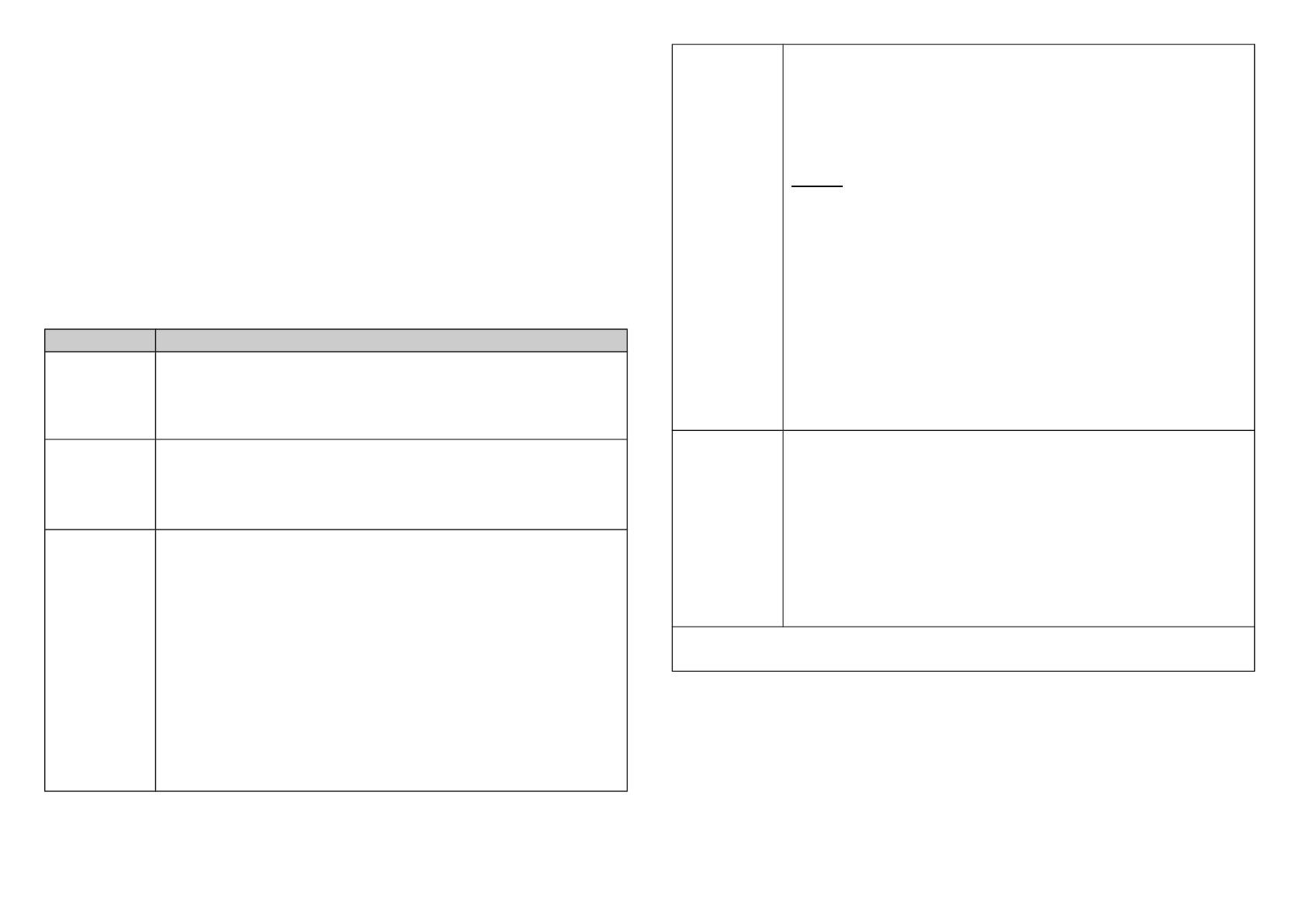
Function Description
Add
1. Have Z-Wave
TM
Controller entered inclusion mode.
2. Pressing tamper key three times within 1.5 seconds
to enter the inclusion mode.
3. After add successful, the LED will light ON 1 second
Remove
1. Have Z-Wave
TM
Controller entered exclusion mode.
2. Pressing tamper key three times within 1.5 seconds
to enter the exclusion mode.
3. Node ID has been excluded.
Reset
Notice: Use this procedure only in the event
that the primary controller is lost or
otherwise inoperable.
1. Pressing tamper key four times within 1.5 seconds
and do not release the tamper key in the 4
th
pressed, and the LED will light ON.
2. After 3 seconds the LED will turn OFF, after that
within 2 seconds, release the tamper key. If
successful, the LED will light ON one second.
Otherwise, the LED will flash once.
3. IDs are excluded and all settings will reset to
factory default.
SmartStart
1. Product has a DSK string , you can key in first five
digit to increment SmartStart process,or you can
scan QR code.
Ex:mydsk
10209-46687-52248-13629-04783-07465-15776-56519
2. SmartStart enabled products can be added into a
Z-Wave network by scanning the Z-Wave QR Code
present on the product providing SmartStart
inclusion. No further action is required and the
SmartStart product will be added automatically
within 10 minutes of minutes On in the network
vicinity.
*notice1:The QR code can be found on the device
PSE04 or on the box.
Association
This machine provides one groups of nodes. Each
group can set 1 Nodes.
Group 1 is called Lifeline the device will report :
1.Notification report
2.Sensor multilevel report
3.Device Reset Locally Notification
4.Battery Report
5.Indicator Report
Failed or success in including/excluding the node ID can be
viewed from Z-Wave
TM
Controller.
Notice 1: Always RESET a Z-Wave
TM
device before trying to add it to a
Z-Wave
TM
network.
4
LED Light Indication
The LED light indicates the different modes of the PSE04
State Type LED Indication
Without Node ID Under normal operation, when the PSE04 has not
been allocated a node ID, the LED light will flash on
and off alternately at 0.5 second intervals. By
pressing the On/Off button, LED light will stop
flashing temporarily.
Learning Slow flashes once when learning is successful.
Alarm Trigger All LED flashes until trigger off.
Z-Wave
TM
Message Report
In default the device will using Notification Report to represent the
tamper trigger event.
* Tamper Report:
When the tamper key is pressed over 5 seconds. The device will into
the alarm state. In that state, if the tamper key be released, the device
will unsolicited to send the report to the nodes in the group 1.
Notification Report (V8)
Notification Type: Home Security (0x07)
Event: Tampering. Product covering removed (0x03)
* Siren State Report:
When the siren start playing or stop the alarm sounds, the device will
unsolicited to send the “Notification Report” to the nodes in the group
1.
Notification Report (V8)
Notification Type: Siren (0x0E)
Event: Siren active (0x01) , Siren idle (0x00)
*Temperature Report:
When the temperature differential over, the device will unsolicited to
send the “Sensor Multilevel Report” to the nodes in the lifeline group.
Sensor Type: Temperature (0x01)
*** Temperature differential report ***
This function default is disable, to enable this function by setting the
configuration NO.5 is greater than 0.
In the default, is disable temperature differential report.
If setting the configuration NO.5 to 1, when the temperature is
changed to plus or minus one degree Celsius (1.8 degree Fahrenheit),
the device will report temperature information to the nodes in the
lifeline group.
The device will measure the temperature in every 10 seconds.
Notice 1:
The PSE04 must stay awake for at least 2 seconds after
communicating, so therefore the more communication, the power
consumption fast, please pay attention to use configuration NO.5.
Notice 2:
This product cannot reflect outdoor temperature immediately
because of the temperature sensor equipped inside rather than surface.
5
*Play Sound:
Using the BASIC_SET or Sound_Switch_Tone_Play_Set to play the
siren, BASIC_SET
or
Sound_Switch_Tone_Play_Set
with Value 0xFF, the
Sound ID will be the same as the value which was set in Configuration
No.7
, 0x00 will stop to play.
Basic Set (V2) or Sound Switch Tone Pley Set (V1)
Value Sound
0x00 Stop Play
0x01 Fire
0x02 Ambulance
0x03 Police
0x04 Alarm
0x05 Ding Dong
0x06 Beep
0xFF Same as configuration NO.7 setting,
or sound switch configuration setting.
* Timing Report:
Beside the event triggered could report message, the device also
support the timing unsolicited report of the status.
Battery level report: Every 6 hours report once in default.
It could be changed by setting the configuration NO. 6.
Low battery report: When the battery level is too low, every 30
minutes will report once.
Temperature report: Every 6 hours report once in default.
It could be changed by setting the configuration NO. 4.
Notice: The configuration NO. 4 and 6 could be setting to
zero to disable the auto report. And the configuration NO. 1 could
change the tick interval, the default value is 30, if setting to 1, that
means the minimum auto report interval will be one minute. And please
notice if setting this value to zero, that means disable all of the timing
report except the low battery detection.
Power Up Procedure
*Battery Power Check
When the device power up, the device will detect the power level of the
battery immediately. If the power level is too low, device will report low
battery even every 30 minutes. Please change another new battery.
*Wake up beam
If a Z-Wave controller or other node in the network needs to
communicate with a battery-powered device such as a door lock, the
controller sends a special beam signal. The purpose of this beam is to
wake up the FLiRS device.
When the FLiRS device receives this beam, it immediately fully wakes
up and then communicates with the controller or other Z-Wave device
utilizing standard Z-Wave protocol commands. If the device does not
hear a Beam it goes back to full sleep for another period until it
partially awakes again and listens for a Beam.
Over The Air (OTA) Firmware Update
The device is supported with Z-Wave™ firmware update via OTA.
1. Set the Z-Wave
TM
Controller into the firmware update mode.
2. Choose the hex file to update the firmware.
3. Wait 10~15 minutes for completing the OTA process.
4. Result of OTA will show in Z-Wave™ Controller log.
6
During the OTA process, please DO NOT remove the power,
otherwise, the firmware will be broken, and the device will be
nonfunctional.
Z-Wave Configuration Settings
Notice 1:
All of the configuration, the data size is 1.
Notice 2:
The reserve bit or not supported bit is allowed any value, but no
effect.
Notice 3:
The PSE04 must stay awake for at least 2 seconds after
communicating, so therefore the more communication, the
power
consumption
fast, please pay attention to use
configuration
NO.1, NO.4,
NO.5, NO.6.
NO. Name Def. Valid Description
1Auto Report
Tick Interval 0x1E 0~255 The interval time for auto report
each tick.
2Sound
Duration 0x06 0~255 Play sound duration, 1 tick is 30
seconds.
3 Customer
Function 0x00 All Customer function switch, using
bit control.
0
Bit0: Disable Trigger Alarm.
0:Enable , 1:Disable.
0
Bit1: Disable Sound. Only using
optical alarm. 0:Enable ,
1:Disable.
0
Bit2: Temperature Unit.
0:Fahrenheit , 1:Celsius.
0
Bit3: Reserve.
0
Bit4: Reserve.
0
Bit5: Reserve.
0
Bit6: Reserve.
0
Bit7: Reserve.
4
Auto Report
Temperature
Time 0x0C 0~255 The interval time for auto report
the temperature.
5
Temperature
Differential
Report
0x00 0~255 The temperature differential to
report.
6Auto Report
Battery Time 0x0C 0~255 The interval time for auto report
the battery level.
7Play Sound
Control
0x43 All Control play sound's level and
which sound.
3
Bit0~1: Play sound's level.
Level 1~3, 0: Level 3.
0
Bit2: Reserve.
0
Bit3: Reserve.
4
Bit4~7: Which sound id will
play, when control form
controller.
Sound ID 1~6, 0: Disable.
7
Z-Wave Supported Command Class
Command Class Version Required Security Class
Z-Wave Plus™ Info 2None
Security 1None
Security 2 1None
Supervision 1None
Transport Service 2None
Association 2Highest granted Security Class
Association Group
Information
3Highest granted Security Class
Device Reset Locally 1Highest granted Security Class
Firmware Update Meta
Data
5Highest granted Security Class
Indicator 3Highest granted Security Class
Manufacturer Specific 2Highest granted Security Class
Multi-Channel Association 3Highest granted Security Class
Powerlevel 1Highest granted Security Class
Version 3Highest granted Security Class
Configuration 4Highest granted Security Class
Sensor Multilevel 11 Highest granted Security Class
Basic 1 Highest granted Security Class
Notification 8 Highest granted Security Class
Sound Switch 1 Highest granted Security Class
Battery 1 Highest granted Security Class
Warning
Caution,
avoid listening at high volume levels for long
periods
CAUTION
Risk of explosion if battery is replaced by an incorrect type.
Dispose of used battery according to the instructions.
Choosing a Suitable Location
1. The suitable ambient temperature for the module/device is
0°C~40°C.
2. Do NOT place the module/device direct under sunlight, in a humid
place or in any location where they may contact moisture, dirt, dust.
3. Do NOT place the module/device where exists combustible
substances or any source of heat, fires, radiators, boiler etc.
Disposal
This marking indicates that this product should not
be disposed with other household wastes throughout
the EU. To prevent possible harm to the
environment or human health from uncontrolled
waste disposal, recycle it responsibly to promote the
sustainable reuse of material resources. To return
your used device, please use the return and
collection systems or contact the retailer where the
product was purchased. They can take this product
for environmentally safe recycling.
Philio Technology Corporation
8F., No.653-2, Zhongzheng Rd., Xinzhuang Dist., New Taipei City
24257, Taiwan(R.O.C)
w ww.philio-tech.com
8
FCC Interference Statement
This equipment has been tested and found to comply with the limits
for a Class B digital device, pursuant to Part 15 of the FCC Rules.
These limits are designed to provide reasonable protection against
harmful interference in a residential installation.
This equipment generates, uses, and can radiate radio frequency en-
ergy and, if not installed and used in accordance with the instructions,
may cause harmful interference to radio communications.
However, there is no guarantee that interference will not occur in a
particular installation.
If this equipment does cause harmful interference to radio or televi-
sion reception, which can be determined by turning the equipment off
and on, the user is encouraged to try to correct the interference by one
of the following measures:
Reorient or relocate the receiving antenna.
Increase the separation between the equipment and receiver.
Connect the equipment into an outlet on a circuit different from that
to which the receiver is connected.
Consult the dealer or an experienced radio/TV technician for help.
This device complies with Part 15 of the FCC Rules. Operation is sub-
ject to the following two conditions:
1. This device may not cause harmful interference, and
2. This device must accept any interference received, including inter-
ference that may cause undesired operation.
FCC Caution: Any changes or modifications not expressly approved by
the party responsible for compliance could void the user's authority to
operate this equipment.
This transmitter must not be co-located or operating in conjunction with
any other antenna or transmitter.
警語
語:
::
:
「取得審驗證明之低功率射頻器材,非經核准,公司、商號或使用者均不得擅自
更頻率、加大功率或變更原設計之特性及功能。
低功率射頻器材之使用不得影響飛航安全及干擾合法通信;經發現有干擾現象時
應立即停用,並改善至無干擾時方得繼續使用。
前述合法通信,指依電信管理法規定作業之無線電通信。低功率射頻器材須忍受
法通信或工業、科學及醫療用電波輻射性電機設備之干擾。」
9
  • Page 1 1
  • Page 2 2
  • Page 3 3
  • Page 4 4
  • Page 5 5
  • Page 6 6
  • Page 7 7
  • Page 8 8
  • Page 9 9

Philio Technology PSE04-B User manual

Type
User manual
This manual is also suitable for

Ask a question and I''ll find the answer in the document

Finding information in a document is now easier with AI