Page is loading ...

Texmate, Inc. Tel. (760) 598-9899 • www.texmate.com
PM-45L Manual (X10) Page 1
High Accuracy LED Meter with 10mV Resolution, True Differential Inputs
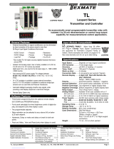
PM-45L
±0.02% Precision Panel Meter with
Differential Input 200PPM/ºC
General Features Specifications
PM-Series, high performance versatility for a wide range of applications
I
nput Configuration: ......... True differential and single-ended
Full Scale Ranges: ............ ±199.99mVDC
±1.9999VDC (standard)
±19.999VDC
±199.99VDC (maximum input signal,
higher voltages can be measured
if voltage dividing resistors are
located externally)
Input Impedance: .............. Exceeds 1000MΩ on 200mV and
2V ranges; 10MΩ on all other ranges
Input Protection: ............... ±170VDC or 120VAC on 200mV
and 2V ranges; ±1200VDC
or 850VAC on all other ranges
Accuracy: ........................... ±0.015% of reading + 2counts
±(0.02% of reading + 3 counts) for
200mV range.
Temperature Coefficient: 5PPM/°C in ratiometric,
200PPM/˚C using internal adjustable
T.C. reference.
Warm Up Time: .................. 10 seconds to specified accuracy
Conversion Rate: .............. 2.5 readings per second
Display:............................... 0.4" LED
Overrange Indication: ...... When input exceeds full scale on
any range being used, most
significant “1” digit & polarity symbol
are displayed with all other digits
blank
Power Requirements: ....... L o w R i p p l e + 4 . 5 t o + 5 . 5 V D C a t 2 2 5 m A
Operating Temperature: .. 0° to +60°C
Storage Temperature: ...... -20° to +70°C
Relative Humidity ............. 95% (non-condensing)
Case Dimensions: ............. Bezel 2.76” x 1.17” (69.75 x 29.7mm)
Depth behind Bezel 3.32”(84mm) plus
0.68” (17.27mm) for connector.
Weight: ............................... 88 gms (3.1 oz)
The PM-45L is a truly unique and extremely versatile instru-
ment. It offers more high performance features than most larger
and more expensive DPM’s.
The meter incorporates a crystal controlled 100KHz clock
that provides an exceptionally high normal mode rejection of
120dB at multiples of 50/60Hz. Bipolar differential and single-end-
ed DC voltages from ±199.99mV to ±199.99V full scale can be
measured and scaled in almost any known engineering unit.
Provision has been made for signal offsetting and the capability
of attenuating both high and low signal inputs. Resolution is 10µV
over ±19999 counts, and errors due to zero drift are virtually elim-
inated by autozeroing. Other optional modes of operation include
an ohmmeter mode, current meter mode and ratiometric mode.
Differencial Inputs
The PM-45L may be used in a wide variety of configurations.
For Differential inputs meter, please use order code ZRS-PMRP
and specify Inputs and Display.
4 1/2 DIGIT with 0.4” LED
4BASIC MODEL NUMBER
PM-45L
....4.5 digit Red LED, Precision Meter w/Differential Input
4SPECIAL OPTIONS (Specify Inputs & Req. Reading)
ZS..........Custom display scaling within standard ranges
ZR-200V ....200 VDC Range Change.
ZR-20V ......20 VDC Range Change.
ZRS-200MV ..200 mVDC range change.
ZRS-PMRP...Non-standard range and scale change including wired
connector.
Z50K........Zero offset 50 K Pot.
4ACCESSORIES
CN-L10 ...... Dual Row 10 Pin Connector, Solder Type
Ordering Information
PM-35A .................... 3.5 digit Red LED, Precision Preference, 2VDC, 5VDC Power
PM-35U.................... 3.5 digit Red LED, Low Cost, 2VDC, 5VDC Power
PM-45L ................ 4.5 digit Red LED, Precision Meter w/Differential Input
PM-45X ............... 4.5 digit LCD, Precision Meter w/Differential Input
PM-45XU ................. 3.5 digit LCD, Low Cost Meter w/Differential Input

Texmate, Inc. Tel. (760) 598-9899 • www.texmate.comPage 2 PM-45L Manual (X10)
Connector Pinouts
The Texmate Model PM-45L is interconnected by means of a
standard PC board edge connector having two rows of 10 pins,
spaced on 0.156" centers.
1
A
2
B
3
C
45678910
D E F H J KL
Calibration Pot
Component Side Solder Side
10 L
9K
8J
7H
6F
5E
4D
3C
2B
1A
OFFSET VOLTAGE OUTPUT
REFERENCE INPUT
SIGNAL LOW INPUT
DECIMAL SELECT (1XX.XX)
DECIMAL SELECT COMMON
DECIMAL SELECT (1X.XXX)
DESPLAY TEST
CLOCK INPUT
BUSY OUTPUT
RUN / HOLD
REFERENCE OUTPUT
SIGNAL HIGH INPUT
ANALOG COMMON
DECIMAL SELECT (1XXX.X)
DECIMAL SELECT (1.XXXX)
NO CONNECTION
DISPLAY DISABLE
CLOCK OUTPUT
+5VDC SYSTEM POWER INPUT
POWER GROUND INPUT
Pin A - Reference Output: Internal precision voltage reference.
Standard output is 1.0000V, adjustable ±5% by R10 potentiometer. The
primary reference voltage of the PM-45L is trimmed by potentiometer
R20 to obtain the optimum compensated temperature coefficient.
Pin B - Signal High Input: Pin B is the signal high input for all input
signal ranges. Optional 200mVDC, 20VDC and 200VDC ranges are
available from Texmate.
Pin C - Analog Common: Pin C is signal return common for differential
inputs, ratiometric inputs, or external reference inputs. For single-ended
inputs, Signal Low Input Pin 3 must be connected to Analog Common Pin
C. To minimize any errors caused by ground loop currents, it is recom-
mended that this connection be made as close as possible to the input
signal source ground.
Pins D, E, 4 and 6 - Decimal Select: Decimal points may be displayed
as required by connecting the appropriate pin to Decimal Select Common
Pin 5. Any number of decimal points can be turned ON at the same time.
An open circuit will turn off the decimal points.
Pin F- No Connection: No connection has been made to this pin.
Pin H - Display Disable: If this pin is connected to the Power Ground
Pin L, the display is disabled and the reading is blanked out. Only the
polarity sign stays on to indicate that power is being applied to the meter.
For normal operation, this pin is left unconnected.
Pin J - Clock Output: A quartz crystal controlled oscillator provides a
stable clock signal output of 100KHz.
Pin K - +5VDC System Power Input: The meter requires a low ripple
DC power supply of 4.5V to 5.5VDC at 225mA. The positive terminal of
the power supply should be connected to Pin K.
Pin L - Power Ground Input: Negative terminal of the +5VDC power
supply should be connected to Pin L. All digital signals, Display Test,
and Run/Hold should be returned to this ground point. Pin L is internally
connected to Analog Common Pin C.
Pin 1 - Reference Input: Reference voltage input for A to D converter.
Normally supplied from Pin A. An external reference source referred to
Pin C may be used instead. Pin 1 may be used as an input for ratiometric
measurements. Minimum usable voltage is 0.1VDC, with a maximum
voltage of 4.0V. For ratiometric operation; Displayed Reading = 10000
x (Signal Input Voltage ÷ Reference Input Voltage). The maximum signal
input voltage is ±4V. Higher voltages must be scaled down through a
voltage divider installed by Texmate. Reference input voltage must remain
stable during measurement period.
Pin 2 - Offset Voltage Output: 0 to +2.490V is available with the
addition of a 3/4", 20KΩ to 100KΩ pot installed by Texmate. The offset
voltage is derived from the internal precision voltage reference and is
available for applications requiring a zero offset such as 4~20mA receiver
and temperature measurements.
Pin 3 - Signal Low Input: Pin 3 is the signal low input for all input
signals. Optional 200mVDC, 20VDC and 200VDC ranges are available
from Texmate.
Pin 5 - Decimal Select Common: Pin 5 serves as a common for the
Decimal Select Pins D, E, 4 and 6. To turn on any required decimal point,
connect the appropriate Decimal Select Pin to Decimal Select Common
Pin 5.
Pin 7 - Display Test: If this pin is connected to the Power Ground Pin L,
all segments of the display come on and 18888 is displayed. For normal
operation, this pin is left unconnected.
Pin 8 - Clock Input: Normally Pin 8 is connected to the 100KHz clock
output from Pin J, thereby providing the optimum rejection of 50/60Hz
noise. For inputs below 100KHz or above 300KHz, contact Texmate for
custom configuration.
Pin 9 - Busy Output: Pin 9 goes to logic “1” at the beginning of the
signal integration and remains at “1” until the first clock pulse after the
zero-crossing is detected at the completion of deintegration. In addition
to its use as a Busy or End-of Conversion signal, the output on Pin 9
can be used in some control applications to indicate the digital reading
of the meter as a function of time or clock pulses. Displayed Reading is
equal to the total clock pulses during Busy less 10,000, or total elapsed
time during Busy, less 100 milliseconds if the clock frequency is 100KHz.
Pin 10 - Run/Hold: If Pin 10 is left open (or connected to +5VDC System
Power Input Pin K for logic control purposes), the meter will operate in a
free-running mode. Under control of the internal 100KHz quartz crystal
clock, readings will be updated every 400mS (2.5 per sec.). If Pin 10 is
connected to Power Ground Input Pin L (logic low), the meter will con-
tinue the measurement cycle that it is doing, then latch up and continu-
ously hold the reading obtained as long as Pin 10 is held low. If Pin 10
is released from Pin L (Pin 10 then goes logic high) for more than 300ns
and returned to Pin L (logic low), the meter will complete one conversion,
update, and then hold the new reading. For all practical purposes, a man-
ually actuated normally closed pushbutton switch will provide sufficient
timing for “press-to-update” operation.
CAUTION: This meter employs high impedance CMOS inputs. Although internal
protection has been provided for several hundred volt overloads, the meter will
be destroyed if subjected to the high kilovolts of static discharge that can be
produced in low humidity environments. Always handle the meter with ground
protection.
45 6 D
E
DECIMAL
SELECT
COMMON DECIMAL SELECT "NOTE: PM-45L meters are intended for use by skilled end users
and support "DIY" features that may permanently modify the
product involved. Texmate CAN NOT provide detailed technical
support or use notes beyond what is covered in our documen-
tation and warranty coverage will only apply to meters in an un-
modied condition. Repair, maintenance, and calibration through
Texmate are available as a paid service through our website or by
sending an RMA request to "[email protected]"."

Texmate, Inc. Tel. (760) 598-9899 • www.texmate.com
PM-45L Manual (X10) Page 3
Component Layout
Signal Conditioning Components
SPAN Potentiometer (Pot)
The SPAN pot is on the right side of the display.
Typical adjustment is 20% of the input signal
range.
ZERO Potentiometer (Pot) optional
The ZERO pot is on the right side of the SPAN
Pot. Typically it enables the displayed reading to
be offset ±500 counts.
Calibration Procedure
VOLTAGE CALIBRATION 2V RANGE
After making the appropriate connections as shown in the instruc-
tions, apply power to the meter. Then, with a precision DC reference
source, apply +1.9000VDC between the Signal High Input Pin B and
the Signal Low Input Pin 3. Adjust R10 potentiometer (on left side as
viewed from rear) until the display reads +1.9000V. NOTE: For other
ranges, the voltage applied should be similarly proportionate to the
particular full scale voltage.
TEMPERATURE COEFFICIENT COMPENSATION
A potentiometer(R20) is factory calibrated so that the output at Test
Point 1 (TP1) referred to Analog Common Pin C, is 2.490V which
provides the optimum temperature coefficient for the average oper-
ating temperature range. For some applications, the user may wish
to adjust the meter’s temperature coefficient. Turn R20 clockwise to
obtain a negative temperature coefficient (higher voltage and positive
TC of primary ref.), and counter clockwise to obtain a positive tem-
perature coefficient (lower voltage and negative TC of primary ref.).
NOTE: Any adjustments of the primary reference voltage will necessi-
tate a recalibration of the meter.
PCB Edge Connector
A standard 20-pin edge con nec tor (two rows of 10 pins on 0.156"
centers) is used to connect the PM-Series of meters. Order part
no. CN-L10.
Optional PCB Edge Connector
PM Case Dimensions and Panel Cutouts
Case Dimensions
TOP VIEW
FRONT VIEW
PANEL CUTOUT SIDE VIEW
16.82mm
0.662in
29.60mm
1.165in
14.50mm
0.571in
64.77mm
2.550 in
24.64mm
0.970in
69.90mm
2.752in
option metal
screw mounting clip
102.36mm
4.030in
84.50mm
3.330in
Edge connector
When extra panel mounting
tightness is required, optional
Screw Mounting Clips can be
purchased seperately and attach
to the sliding mounting side clips
8.50mm
0.335in
2.50mm
0.098in
TC Adjusting Potentiometer
(R20)
TP1
Span Pot
(R10)

Texmate, Inc. Tel. (760) 598-9899 • www.texmate.comPage 4 PM-45L Manual (X10)
Copyright © 2022 Texmate Inc. All Right Reserved.
WARRANTY
Texmate warrants that its products are free from defects in material and workmanship under
normal use and service for a period of one year from date of shipment. Texmate’s obligations
under this warranty are limited to replacement or repair, at its option, at its factory, of any of
the products which shall, within the applicable period after shipment, be returned to Texmate’s
facility, transportation charges pre-paid, and which are, after examination, disclosed to the sat-
isfaction of Texmate to be thus defective. The warranty shall not apply to any equipment which
shall have been repaired or altered, except by Texmate, or which shall have been subjected
to misuse, negligence, or accident. In no case shall Texmate’s liability exceed the original pur-
chase price. The aforementioned provisions do not extend the original warranty period of any
product which has been either repaired or replaced by Texmate.
USER’S RESPONSIBILITY
We are pleased to offer suggestions on the use of our various products either by way of printed
matter or through direct contact with our sales/application engineering staff. However, since
we have no control over the use of our products once they are shipped, NO WARRANTY
WHETHER OF MERCHANTABILITY, FITNESS FOR PURPOSE, OR OTHERWISE is made
beyond the repair, replacement, or refund of purchase price at the sole discretion of Texmate.
Users shall determine the suitability of the product for the intended application before using,
and the users assume all risk and liability whatsoever in connection therewith, regardless
of any of our suggestions or statements as to application or construction. In no event shall
Texmate’s liability, in law or otherwise, be in excess of the purchase price of the product.
Texmate cannot assume responsibility for any circuitry described. No circuit patent or software
licenses are implied. Texmate reserves the right to change circuitry, operating software, speci-
fications, and prices without notice at any time.
1934 Kellogg Ave. Carlsbad, CA 92008
Tel: 1-760-598-9899 • USA 1-800-839-6283 • That’s 1-800-TEXMATE
• Email: [email protected] • [email protected]
• Web: www.texmate.com
PM-45L Technical Manual Copyright © 2022 Texmate Inc. All rights reserved.
Published by: Texmate Inc. USA. Information in this Technical Manual is
subject to change without notice due to correction or enhancement. The in-
formation described in this manual is proprietary to Texmate, Inc. and may
not be copied, reproduced or transmitted, in whole or in part, in connection
with the design, manufacture, or sale of apparatus, device or private label
product without the express written consent of Texmate, Inc.
/