Page is loading ...

ZRS 6060
Retroreflectometer
Firmware as from v.1.0
Instruction manual

Page 2
Index
Exclusion of liability ................................................... Error! Bookmark not defined.
1 Description of device........................................................................................... 7
2 Safety information ............................................................................................... 8
2.1 Symbols used ............................................................................................... 8
2.2 Safety notes and hints .................................................................................. 8
3 Delivery of device ............................................................................................... 9
3.1 Damages during carriage ............................................................................. 9
3.2 Shipment ...................................................................................................... 9
3.3 Standard delivery ........................................................................................ 10
3.4 Shoulder bag .............................................................................................. 11
3.5 Options with modification of the ZRS 6060 (built-in) ................................... 11
3.6 Options without modification of the ZRS 6060 ............................................ 11
4 Device overview ................................................................................................ 13
4.1 Adjustable display inclination ...................................................................... 14
4.2 Main window ............................................................................................... 14
5 Setting up .......................................................................................................... 17
6 Navigation ......................................................................................................... 17
6.1 Activation / Deactivation ............................................................................. 17
6.2 Scrolling ...................................................................................................... 17
6.3 Exit.............................................................................................................. 17
7 Calibrate ........................................................................................................... 18
7.1 Front plate with calibration standard ........................................................... 18
7.2 Cleaning of the calibration standard ........................................................... 19
7.3 Calibration on calibration standard ............................................................. 19
7.4 Calibration on second calibration standard ................................................. 21
8 Measure ............................................................................................................ 24
8.1 General ....................................................................................................... 24
8.2 Practical examples ..................................................................................... 24
8.3 Preparation and safety precautions ............................................................ 25
8.4 Single measurements ................................................................................. 25
8.5 Average measurements .............................................................................. 26
8.6 Pass/Fail measurements ............................................................................ 26

Page 3
8.7 Interval timer measurements ....................................................................... 27
8.8 Edit, delete and store measurements .......................................................... 28
9 Quickstart menu ................................................................................................ 29
10 Options .............................................................................................................. 29
10.1 Illumination adapters ................................................................................. 29
10.2 Handles ..................................................................................................... 30
10.2.1 Mounting of the handles ................................................................... 30
10.2.2 Dismounting ..................................................................................... 33
10.3 Camera...................................................................................................... 34
10.4 WAAS GPS-unit ........................................................................................ 35
10.5 Barcode reader and QR barcode reader ................................................... 37
10.5.1 General ............................................................................................ 37
10.5.2 Barcode measurements ................................................................... 37
10.5.3 QR barcode measurements ............................................................. 38
11 Archive............................................................................................................... 39
11.1 Sorting of the measurements .................................................................... 39
11.2 Overview measurements (sorted) ............................................................. 40
11.3 Detailed entry information .......................................................................... 40
11.4 Input of additional information ................................................................... 40
11.5 Printing of a measuring report ................................................................... 41
11.6 Storing the measuring data on USB flash drive ......................................... 42
12 Data export and MappingTools software ........................................................... 43
12.1 Interfaces ................................................................................................... 43
12.2 PC Mode ................................................................................................... 43
12.3 Storing the measuring data on a USB flash drive ...................................... 43
12.4 Mapping and data analysis software MappingTools .................................. 43
12.5 Data export to Microsoft® Excel ................................................................. 44
13 Menu ................................................................................................................. 46
13.1 Menu structure .......................................................................................... 46
13.2 Navigation in the menu .............................................................................. 47
13.3 Measure mode .......................................................................................... 47
13.3.1 Auto save measurements ................................................................ 47
13.3.2 Average ........................................................................................... 47

Page 4
13.3.3 Pass/Fail ......................................................................................... 48
13.4 Timer – Interval timer ................................................................................ 48
13.5 Jobs .......................................................................................................... 49
13.6 Setup ........................................................................................................ 49
13.6.1 User ................................................................................................ 49
13.6.2 Language ........................................................................................ 50
13.6.3 Date and time .................................................................................. 51
13.6.4 Power .............................................................................................. 51
13.6.5 Sound .............................................................................................. 51
13.6.6 Database ......................................................................................... 51
13.6.7 Camera ........................................................................................... 52
13.6.8 Printer ............................................................................................. 53
13.6.9 Calibration ....................................................................................... 53
13.6.10 Units .............................................................................................. 53
13.6.11 Display .......................................................................................... 54
13.6.12 Options .......................................................................................... 54
13.6.13 Reset settings to factory default .................................................... 54
13.7 Diagnostics ............................................................................................... 55
14 Built-in battery and charging ............................................................................. 56
14.1 Battery ...................................................................................................... 56
14.2 Battery status indication on the display..................................................... 56
14.3 Charging ................................................................................................... 56
15 Status and error messages ............................................................................... 57
15.1 General ..................................................................................................... 57
15.2 Status message “Battery voltage is critical” .............................................. 57
15.3 Status message “Please calibrate 0.2°” .................................................... 57
15.4 Error message “Calibration is not OK” ...................................................... 58
15.5 Error message “Factory calibration has expired” ...................................... 58
15.6 Reset of ZRS 6060 ................................................................................... 59
16 Maintenance and cleaning ................................................................................ 59
16.1 Maintenance carried out by the user......................................................... 59
16.2 Cleaning ................................................................................................... 60

Page 5
16.3 Adjustment of display inclination resistance .............................................. 61
17 Technical specifications ..................................................................................... 61
Glossary .................................................................................................................. 63

Page 6
Exclusion of liability
Illustrations, descriptions as well as the technical specifications conform to the
instruction manual on hand at the time of publishing or printing.
However, Proceq SA policy is one of continuous product development. All changes
resulting from technical progress, modified construction or similar are reserved
without obligation for Proceq SA to update.
Some of the images shown in this instruction manual may be of a pre-production
model and/or are computer generated; therefore, the design / features of the
delivered product may differ in various aspects.
The instruction manual has been drafted with the utmost care. Nevertheless, errors
cannot be entirely excluded. The manufacturer will not be liable for errors in this
instruction manual or for damages resulting from any errors.
The manufacturer will be grateful at any time for suggestions, proposals for
improvement and indications of errors.
© Proceq SA

Page 7
1 Description of device
The ZRS 6060 is an ergonomic retroreflectometer for determination of night visibility
(coefficient of retroreflection RA and R’) of traffic signs, safety garments and other
reflective materials with measurement of three different observation angles at the
same time.
In particular, this instrument has the following features
• The very first retroreflectometer with LED illumination system and with a 3.5”
high resolution colour touchscreen with adjustable display inclination for
excellent visibility under all lighting conditions, even in bright sunlight
• Innovative options to customize the reflectometer to personal requirements:
integrated 5-megapixel camera, WAAS GPS-unit, holster and handles
• Easy and quick calibration with only a single working standard
• For all kinds of retroreflective materials and colours with automatic colour
indication
• Continuously updated average value; each single measurement is stored
additionally
• Integrated measurement of temperature (°C / °F) and relative humidity (% rF)
• Measurements can be evaluated with the included mapping and data analysis
software „MappingTools”
• Easy to operate with multilingual menu navigation
• Sturdy construction and ergonomic design

Page 8
2 Safety information
2.1 Symbols used
This note comprises instructions needed to follow directions, specifications,
proper working procedure and to avoid data loss, damage or destruction of
the instrument.
This note signifies a warning about dangers to life and limb if the apparatus
is handled improperly. Observe these notes and be particularly careful in
these cases. Also inform other users on all safety notes. Besides the notes
in this instruction manual the generally applicable safety instructions and
regulations for prevention of accidents must be observed.
2.2 Safety notes and hints
It is strictly forbidden to open the housing of the ZRS 6060! If not
observed, all guarantee and liability claims to Proceq SA will be void.
The ZRS 6060 is a high quality, state of the art instrument and is safe to
operate. Nevertheless, risks may occur during improper use.
Every person working with the ZRS 6060 or maintaining the ZRS 6060 must
read and understand the manual completely in particular the safety
precautions and warnings.
The ZRS 6060 is exclusively intended for determination of the night visibility
(coefficient of retroreflection RA and R’) of traffic signs, safety garments and
other reflective materials with measurement of three different observation
angles at the same time. Any other use is considered as not being in
accordance with the intentions of the manufacturer. The manufacturer is not
liable for damage resulting from inappropriate application. The user bears
full responsibility.
Never leave the ZRS 6060 under direct sunlight exposure over a longer
period. Always store it in it´s shoulder bag.
Unauthorized modifications and changes of the ZRS 6060 are not allowed.
Unauthorized reproduction is not permitted.
Proceq SA refuses all warranty and liability claims for damages caused by
usage of the ZRS 6060 in combination with non-original accessories, or
accessories from 3rd party suppliers.
All maintenance and repair work which is not explicitly allowed and
described in this manual (see chapter 16.1 on page 59) shall only be carried
out by Proceq SA or your authorized Proceq agent, failure to comply voids
warranty.
Make sure that the ZRS 6060 is turned off and unplugged before any
maintenance.
For the operation of the ZRS 6060 apply all local safety regulations.

Page 9
3 Delivery of device
3.1 Damages during carriage
On receipt of the goods, check for any visible damages on the packaging. If it is
undamaged you may sign the receipt of the goods. If you do suspect by your visual
inspection that damage has occurred, make a note of the visible damage on the
delivery receipt and request the courier to countersign it. Moreover, the courier must
be held responsible for the damage in writing.
If any damages are discovered during unpacking, you have to inform and hold the
courier liable immediately in the following way: “When opening the parcel, we
noticed that … etc. “This superficial checking of the goods has to be done within a
time limit set by the carrier, which is normally 7 days. However, this period may vary
depending on the courier. Hence, it is recommended to check the exact time limit
when receiving the goods.
If there are any damages also inform your authorized Proceq agent or Proceq SA
immediately.
3.2 Shipment
Should the device be transported again, it must be packaged properly. Preferably
use the original packaging for later shipments. Additionally, use filling material in the
package to protect the device from any shock during carriage.

Page 10
3.3 Standard delivery
The following parts are included in the delivery:
1 Retroreflectometer
1 calibration standard / front plate
1 battery charger (100 – 240V, 50-60 Hz)
1 mapping and data analysis software
„MappingTools“
1 USB-cable for data transfer to computer
1 certificate of manufacturer
1 certificate of calibration
1 shoulder strap
1 shoulder bag

Page 11
3.4 Shoulder bag
The ZRS 6060 is delivered in a shoulder bag. Whenever you want to transport the
instrument, use this shoulder bag. Additionally, for shipments the shoulder bag has
to be put into a cardboard box and protected with filling material. The shoulder bag
is at the same time an optimal storage case for the ZRS 6060. The calibration
standard / front plate always has to be mounted on the ZRS 6060 before stowing it
in the shoulder bag.
3.5 Options with modification of the ZRS 6060 (built-in)
WAAS GPS-unit
holster
barcode reader
QR barcode reader
5-megapixel camera
It is recommended to buy any desired built-in options when purchasing the
ZRS 6060. All options can be retro-fitted, but some require return to the
manufacturer for installation.
3.6 Options without modification of the ZRS 6060
portable USB-printer

Page 12
handle 1.2 m
extendable handle from 1.7 m to 3 m (66.9” –
118.1”)
extendable handle from 2.2 m to 4 m (86.6” –
157.5”)
adapter for illumination (entrance) angle 20°
adapter for illumination (entrance) angle 30°
adapter for illumination (entrance) angle 40°
adapter for illumination (entrance) angle 45°
voltage converter DC/AC 12V/230V to be plugged
into the cigarette lighter
Proceq SA refuses all warranty and liability claims for damages caused by
usage of the ZRS 6060 in combination with non-original accessories, or
accessories from 3rd party suppliers.

Page 13
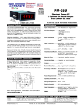
4 Device overview
(4)
(5)
(1)
(11)
(3)
(10)
(7)
(6)
(14)
(9)
(8)
(2)
(13)
(12)
(15)
(2)
(2)
(4)
(5)
(5)
(5)
(6)
(6)
(6)
(7)
(8)
(9)
(10)
(14)
(16)

Page 14
(1) On/off button
(2) Measuring button
(3) Quick start menu button
(4) Touchscreen with adjustable display inclination
(5) Handle
(6) Integrated battery
(7) Calibration standard / front plate
(8) Suspension clip
(9) Cover of connection socket for battery charger and optional handles
(10) Cover string
(11) Label
(12) Host USB-interface (type A)
(13) Mini USB-interface (type B)
(14) Thread socket for mounting optional handles
(15) Measuring area
(16) Adjusting screw for display inclination resistance of touchscreen
4.1 Adjustable display inclination
The ZRS 6060 is equipped with an adjustable display inclination. This ensures an
optimal visibility of the display in all conditions.
Pull the upper part of the display ahead until you reach the optimal angle. The
display inclination can be adjusted seamlessly between the standard vertical
position and the maximum tilted position.
Standard position One of many positions Maximum tilted position
Always put the adjustable display back into the standard vertical position
before storage.
4.2 Main window
Display view in single mode

Page 15
Main window Enlarged view Overview
Display view in average mode
Main window Enlarged view Overview
(22)
(17)
(18)
(19)
(20)
(21)
(21)
(21)
(23)
(25)
(26)
(27)
(23)
(31)
(28)
(28)
(28)
(30)
(17)
(18)
(19)
(30)
(29)
(20)
(20)

Page 16
(3) Quick start menu
(17) Enlarged view icon
(18) Overview icon
(19) Main window icon
(20) Average mode is activated
(21) Colour identification of measuring sample determined atomatically
(22) Observation angle
(23) Single values of observation angle
(24) Average value of observation angle
(25) Temperature and relative humidity
(26) Illumination (entrance) angle
(27) Battery status
(28) Current job
(29) Last single measurement in average mode
(30) Number of single measurements of the current calculated average
value
(31) GPS-status

Page 17
5 Setting up
Press the on/off button shortly to switch on the unit.
Older ZRS 6060 versions can be put into stand-by mode. This enables a fast
switch-on in a few seconds. To switch the unit into stand-by-mode, press the on/off
button shortly.
If the battery was completely empty or the unit was not used for a longer period, it
takes about 30 seconds to boot up, as the ZRS 6060 was shut off completely. To
shut off the unit completely, press the on/off button for at least 8 seconds.
Press the measuring button continuously during switch-on to get directly to the
language settings.
The „auto off time“ and in case of older units the „auto sleep time“ can be set in the
menu, see chapter 13.6.4 “Power” on page 51.
6 Navigation
6.1 Activation / Deactivation
Certain functions can be activated / deactivated by tipping on the corresponding
icon on the display.
This is either shown with a white tick on green background for active functions, a
green tick for chosen menu options, a yellow highlight e.g. for active control
elements or a grey highlight e.g. for chosen measurements.
6.2 Scrolling
For scrolling use either the navigation arrows and or your fingers by
pressing and pulling into the desired direction.
6.3 Exit
The measuring mode can be opened by triggering the measuring button from every
function. The only exceptions are functions with a “cancel” button . These
have to be interrupted first by pressing the button. In certain functions there
is a backwards arrow to get back a level.

Page 18
7 Calibrate
7.1 Front plate with calibration standard
The front plate with calibration standard should always be mounted on the ZRS
6060. For measurements, it must be mounted in the measuring position, for
calibration in the calibration position.
Mounted in the Removing calibration standard, Mounted in the
Measuring position turning and remounting calibration position
If the front plate with calibration standard is
properly mounted in the measuring position, no
status message will be displayed.
If the front plate with calibration standard is not
mounted, the status message „Plate is missing“ is
displayed. Should you carry out a measurement
without front plate, the illumination angle 0° will be
stored at the measurement. If the front plate with calibration standard is
properly mounted in the calibration position, the
status message „Standard is mounted“ is
displayed. Should you carry out measurements
with mounted calibration standard, this
information will be stored with the measurements.
Depending on version, there are two front plates with calibration standard – with
illumination angle (β) +5°and with illumination angle (β) -4°
Backside of a front plate with calibration standard as an example

Page 19
Label of the calibration standard with following
information:
- article number
- serial number
- illumination (entrance) angle (β)
- observation angles
- calibration values
- expiry date of calibrationstandard
calibration standard – measured in factory
After the expiry date of the calibration standard
a factory calibration of the ZRS 6060 and its corresponding calibration
standard is required. Contact either Proceq or your authorized Proceq agent.
The calibration standard delivered with the ZRS 6060 is not interchangeable
and is valid only for the delivered instrument.
Always protect the calibration standard from dust, moisture and other
environmental factors, keep it mounted on the ZRS 6060 and store the
instrument in its shoulder bag.
7.2 Cleaning of the calibration standard
The calibration standard can be cleaned using standard window cleaner and a soft
cloth.
A damaged or a polluted calibration standard may cause incorrect calibration
and therefore incorrect measuring results.
7.3 Calibration on calibration standard
Should the unit indicate that the calibration is outdated
or it is required by the regulations, the ZRS 6060 has
to be calibrated. The calibration interval can be
changed as described in chapter 13.6.9 “Calibration”
on page 53.

Page 20
Press the symbol and to open the calibration
function. By pressing you trigger the
calibration.
After calibration a message is displayed showing the
calibration results. Confirm the successful calibration
with .
Should the calibration not be OK (e.g. the standard or
the optical window is damaged or soiled), the
instrument will inform accordingly
Reject the wrong calibration with , eliminate the
cause e.g. by cleaning and recalibrate.
Should the calibration still not be OK after trying several times and despite
cleaning the calibration standard and the optical window, it might be
necessary to send the instrument to the manufacturer for maintenance and
calibration. Please contact Proceq or your authorized Proceq agent.
/