Page is loading ...

Radiators Line TS2000 Series
Natural draught system gas convectors for heating of small
size rooms, with no need of electrical power supply
Natural gas/LPG fired
Installation, use and
maintenance manual


TABLE OF CONTENTS
SECTION 1 GENERAL INSTRUCTIONS..................................................................................... 3
1.1 PRODUCT DESCRIPTION AND MAIN OPERATING CHARACTERISTICS .................... 4
1.2 TECHNICAL DATA.............................................................................................................5
SECTION 2 INSTALLATION OF THE HEATER........................................................................ 6
2.1 SEQUENCE OF INSTALLATION ....................................................................................... 7
2.2 CONNECT THE CONVECTOR TO THE GAS NETWORK ............................................... 9
2.2.1 NATURAL GAS FEEDING ................................................................................................. 9
2.2.2 L.P.G. GAS FEEDING ........................................................................................................ 10
2.3 HOW TO REPLACE THE BURNER INJECTOR................................................................ 10
2.4 GAS CONVERSION ........................................................................................................... 10
SECTION 3 USE AND OPERATION OF THE UNITS.............................................................. 11
3.1 STARTING OF THE UNIT .................................................................................................. 11
3.2 OPERATION OF THE UNIT ............................................................................................... 11
SECTION 4 MAINTENANCE AND SERVICE............................................................................. 12
4.1 TURNING OFF OF THE UNIT........................................................................................... 12
4.2 IMPROPER OPERATING PROCEDURES........................................................................ 12
4.3 TYPE OF FAILURES AND SERVICING ............................................................................ 12
4.4 MAINTAINANCE................................................................................................................. 13
4.5 SERVICING ........................................................................................................................ 13
All the instructions contained in this manual should be carefully read. They contain important instructions
regarding installation, use, maintenance and safety. Keep this manual for any further need of information.
The manufacturer cannot be held responsible for any damage due to improper, erroneous or irrational
use.
NOTE

Installation, Maintenance and User Manual
2
L.P.G. / Natural Gas Convectors Series TS 2000

Installation, Maintenance and User Manual
3
L.P.G. / Natural Gas Convectors Series TS 2000
This manual is an integral and essential part of this product and must be given to the end user.
This unit (Direct-Vent Wall Gas Convector) must be exclusively used for the purpose it was intended. Any other
use is to be considered improper and therefore dangerous.
The manufacturer cannot be held responsible for any damage resulting from incorrect installation or failure to
comply with the manufacturer’s instructions.
In case of failure and/or bad/poor operation, stop the unit (shut off the gas supply) do not attempt any repair or
direct servicing. Call only qualified service engineer. Qualified service engineers are those having specific
technical experience in the installation of heating units for residential applications, designated by a local
authority.
The service on the unit should be carried out only by a technical centre authorized by the manufacturer, using
only original spare parts.
Any misapplication of the above instructions can compromise the safety of the unit.
To ensure the efficiency of the unit and its proper operation, it is essential that a qualified service engineer
carries out annual maintenance in accordance with the manufacturer’s instructions.
Should the unit be sold or transferred to another owner, ensure that the manual remains with the unit for the use
of the new owner and/or the installer.
Qualified personnel must check:
• that the electrical and the gas supply ratings do exactly correspond to those shown on the original rating
plate.
• that the exhaust flue and the inlet air supply are properly installed.
• that the combustion air feed and exhaust are properly fitted in accordance with the existing standards..
• the proper internal and external sealing of the combustion apparatus.
• that fuel flow control is in accordance with the unit power requirements.
• that the unit is fed with the specific type of fuel for which it has been pre-set.
• that the fuel supply pressure is within rated limits.
• that the fuel supply system is suitable for the unit and that all safety and control devices required by the
existing standards are duly installed.
Do not use gas pipes to earth electric apparatus.
Avoid unnecessary supply when the unit is not in use and always close the gas valve.
In case of prolonged absence isolate the main gas inlet valve to the unit.
• do not activate electric switches, telephones or any other object or device that may cause sparks.
• immediately open doors and windows to create drafts of air that purify the room.
• shut off gas supply.
• call for Qualified Servicing Engineer.
1 GENERAL INSTRUCTIONS
BEFORE STARTING THE UNIT
IF YOU SMELL GAS

4 Installation, Maintenance and User Manual
L.P.G. / Natural Gas Convectors Series TS 2000
1.1 PRODUCT DESCRIPTION AND MAIN OPERATING CHARACTERISTICS
Il TS2000 gas heater is an independent heating product with an isolated combustion chamber and balanced flue
natural draught.
It can operate either with natural gas and liquid propane gas (category II
2H3B/P
, type C11, regulation EN 613).
Il prelievo dell’aria di combustione e lo scarico dei fumi avvengono all’esterno dell’ambiente di installazione
mediante due tubi coassiali. Pertanto l’apparecchio dovrà essere posizionato su una parete perimetrale esterna.
The combustion air intake and the exhaust of fumes are external to the system through two coaxial pipes.
Therefore, the unit will have to be installed on an external perimeter wall.
Precisely because of the dual function (the intake and flue exhaust) of the coaxial pipe, you cannot make a
connection with a traditional chimney.
The operation principle of TS2000 hater is based on a convective movement of the ambient air. The air going
through the unit is drawn upwards and heated then diffused in the ambient through the outlet grille. This
convective motion is natural.
For this reason, you should not place on the grid clothing, newspapers or any other object that could obstruct
the air flow: also make sure that curtains, backs of chairs or furniture are not placed at a distance of less than 30
cm from the unit.
The operation of the unit is very simple and completely automatic thanks to the thermostatic regulation: the end
user only needs to start the unit and choose the desired temperature (to be selected on the thermostat).
Since the combustion chamber of the unit is completely sealed (C-type unit), the installation of grids or holes
in the room, for ventilation, are not necessary.
The Room sealed combustion circuit is the best safety feature for the premises where the unit is to be installed:
there is no risk of leakage of the combustion products and neither the oxygen necessary for the combustion has
been taken from indoor.
A special flame detection device, that operates through a thermocouple, immediately stops the gas supply in
case the flame accidentally goes off.

Installation, Maintenance and User Manual
5
L.P.G. / Natural Gas Convectors Series TS 2000
1.2 TECHNICAL DATA
DESCRIPTION U.M. VALUE
TYPE OF EQUIPMENT
C
11
UNIT CATEGORY
II
2H3B/P
MAXIMUM NOMINAL HEAT INPUT
kW 1,97
MAXIMUM NOMINAL HEAT OUTPUT
kW 1,69
GAS CONSUMPTION NATURAL GAS (G20)
(15°C - 1013 mbar) L.P.G.* (G30)
m
3
/h
kg/h
0,20
0,15
EFFICIENCY (EFFICIENCY CLASS NO.1 ”ONLY HEATING”)
% 86
BURNER PRESSURE NATURAL GAS (G20) MAX
REDUCED
mbar
mbar
15,2
6,8
BURNER PRESSURE L.P.G. (G30 BUTANE ) MAX
REDUCED
mbar
mbar
29
14
BURNER PRESSURE L.P.G. (G31 PROPANE) MAX
REDUCED
mbar
mbar
29
18
FEEDING PRESSURE NATURAL GAS (G20)
L.P.G. (G30)
mbar
mbar
20
30
MAIN BURNER NOZZLE DIAMETER NATURAL GAS (G20)
L.P.G. (G30)
mm
mm
1,30
0,75/0,80
PILOT NOZZLE DIAMETER NATURAL GAS (G20)
L.P.G. (G30)
mm
mm
0,30
0,30
Ø HOLE DIAMETER FOR CONCENTRIC INLET/OUTLET PIPE AIR INLET
FLUE GAS
mm
mm
100
60
WALL THICKNESS MAX
MIN
mm
mm
500
150
GAS CONNECTION
” 3/8
WEIGHT
kg 16,8
* VALUE WITH A PROPANE - BUTANE MIXTURE (70% PROPANE - 30% BUTANE)
ACCORDING TO EU NORM EN 613
Table 1 – TEHCNICAL DATA

6 Installation, Maintenance and User Manual
L.P.G. / Natural Gas Convectors Series TS 2000
17
10
48 cm
19 29
10
10
max 35
min 5
10
10
57,7 cm
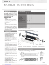
Figura 1 – EXTERNAL DIMENSIONS AND INSTALLATION LIMITS
The installation shall be made, according to the Manufacturer’s instructions, by qualified service engineers.
An incorrect installation can cause damages to people, animals and property. In case of erroneous installation,
the Manufacturer cannot be held responsible for such damages.
The installation must be performed in compliance with the existing European laws, rules and regulations
referred to gas and electrical appliances.
In particular it must be respected all related to the distance between the external flue terminal and windows,
balconies, gutters, etc., and distances to the soil or to the sidewalk.
The unit is delivered with concentric pipes for walls with max thickness 50 cm.
For the correct installation is required to respect the following conditions:
1. The gas convector must be installed indoor on an external perimeter wall, respecting the distances indicated
in Figura 1, so that a minimum space for technical service and maintenance is foreseen. The minimum
recommended distance from the basement is 5 cm and possibly not superior to 35 cm because, for bigger
height, there will be a non uniform distribution of the heat in the building.
2. Keep a minimum distance of 10 cm between the sides of the gas convector and any type of object in order
to permit the dismounting and remounting of the panel.
3. If a bracket, shelf etc. would be installed above the unit, a space of 10 cm (at least) between the top of the
unit and the bracket must be considered. MOREOVER DO NOT INSTALL ANY KIND OF COVERAGE ON
THE UNIT.
4. The external flue terminal must not be nearer than 40 cm to obstruction like: angles, pipes, gutter-pipes,
bushes, wires, etc.
5. If the exhaust terminal should come out at a lower height than 2 metres from the ground, you should install
a protection grid (Cod.O-12456340).
6. Make sure that adequate furniture and network of gas exists.
2 INSTALLATION OF THE HEATER
NOTE

Installation, Maintenance and User Manual
7
L.P.G. / Natural Gas Convectors Series TS 2000
2.1 SEQUENCE OF INSTALLATION
Before unpacking the unit check that the external packaging is in good condition and that no damage has
occurred during transportation, if so promptly contact your supplier.
Then proceed like follows:
1. Unpack the unit from its protection wrapping, slip off the inlet and outlet flues first. DO NOT DAMAGE OR
THROW AWAY THE TEMPLATE where a drilling guide for the correct installation of the unit is given.
2. Fix the template to the wall where the unit is to be installed making sure it is perpendicular to the floor, and
then point on the wall the holes where to locate the inlet/exhaust pipe and the support bracket.
3. Drill a hole (Ø 100 mm) to locate the main pipe on the wall with max. thickness 500 mm. The hole can be
realised by a rotary cutter. Drill also the holes Ø 6 mm to fix the support bracket (for the insertion of the
support frame).
If the unit must be installed on a wall with flammable material on it (such as upholstery, etc.) it is necessary to
remove part of this material on the wall till a diameter of 130 mm around the flue hole, in order to reach the
bare wall If it’s not possible to remove the only the flammable layer (for example: walls made entirely of wood)
it will be necessary to break through the wall near the pipes to a depth of 30 mm (see Figura 2).
4. Through the plastic anchors provided, fix the
support bracket on the wall, being sure that the
holes placed on the two sides are positioned in
the lower part of the bracket (see Figura 3).
Be also sure that the bracket is horizontal.
5. Adapt the length of the pipes (exhaust outlet and
intake air) to the effective depth of the wall,
cutting the exceeding part: for the exact length
see Figura 4.
6. Remove the casing from the heater body,
unscrewing the two mounting screws. (see
Figure n.5).
Figura 2
Figura 3
Figura 4
7. Insert the smallest tube (diameter Ø 60 mm) in the combustion chamber (see Figura 6). Mount the largest
tube (Ø 100 mm) and the gasket on the unit frame with the screws provided. (see Figura 7).
8. Position the heater on the wall inserting the inlet/outlet flue in the hole previously drilled. Make sure that the
edges of the support bracket perfectly match the existing holes in the back on the unit (see Figura 8).
WARNING
130 mm
30 mm
A + 9 cm
A + 1 cm
A

8 Installation, Maintenance and User Manual
L.P.G. / Natural Gas Convectors Series TS 2000
9. Attach the heater the support bracket with the two screws provided. During this operation make all
necessary adjustments to have a correct installation of the unit.
10. Mount the vent cap on the flue pipe and fix it with the three self–tapping screws provided. (see Figura 9).
Figura 5
Figura 6
Figura 7
Figura 8
11. Connect the gas supply line.
12. Reinstall the external casing by tightening the
relevant screw (see Figura 5).
13. Turn on gas supply and check the correct
functioning according to the next paragraph
“CONNECT THE CONVECTOR TO GAS
NETWORK”.
Figura 9
Cod.A0092
Cod.A0093
Cod.A0094
Cod.A0198
Ø 60 mm
Ø 100 mm

Installation, Maintenance and User Manual
9
L.P.G. / Natural Gas Convectors Series TS 2000
2.2 CONNECT THE CONVECTOR TO GAS NETWORK
The wall gas convector TS2000 is supplied to operate with natural gas and is equipped with an LPG conversion
kit. During the final quality tests in the factory each unit is set to operate with natural gas. The gas valve is
produced by SIT model EUROSIT (see Figura 10). Subsequent adjustments can be carried out on the spot,
following these instructions.
Figura 10 – VALVOLA EUROSIT
2.2.1 NATURAL GAS FEEDING
In order to adjust the gas valve, after having removed the casing and checked if the unit is prepared to operate
with natural gas (if you need to operate with LPG please see next paragraph; if you need to change the nozzle
please see paragraph 2.3 & 2.4), please proceed like it follows:
REGULATION FOR MAXIMUM AND REDUCED HEAT OUTPUT
The regulation for maximum heat output must be carried out with an operating unit in a room with an ambient
temperature not higher than 20° C and after having positioned the temperature regulation knob on the max
value (position 7).
In case of installations with ambient temperatures above 20° C, you should dip the sensor bulb into cold water,
after having detached it from the related supports.
1. Connect a pressure gauge to outlet pressure (T) placed on the valve (see Figura 10).
2. Make sure that the value is 15.2 mbar.
3. Regulate the pressure to the burner by means of the screw for hi pressure adjustment (P) in clockwise
sense to increase it and in counterclockwise to decrease it, and set the pressure at the requested value.
Proceed now to the pressure regulation at the reduced heating power as indicated here below:
Cod.A0157
(M) CONTROL KNOB
(Q) SCREW FOR Lo
PRESSURE ADJUSTMENT
(Y) GAS PRESSURE ADJUSTMENT
FOR THE PILOT FLAME
(T) TEST GAUGE
CONNECTION FOR
GAS MANIFOLD PRESSURE
(T) TEST GAUGE
CONNECTION FOR
GAS INLET PRESSURE
(P) SCREW FOR HI PRESSURE
ADJUSTMENT
TEMPERATURE SENSOR

10 Installation, Maintenance and User Manual
L.P.G. / Natural Gas Convectors Series TS 2000
4. With the pressure gauge connected and the unit operating, slowly turn the knob to the position as close as
possible to shutdown position.
5. Make sure that the value is 6.8 mbar.
6. Regulate the pressure to the burner by means of the screw for LO pressure adjustment (Q) in
counterclockwise sense to increase it and in clockwise sense to decrease it, and set the pressure at the
requested value.
7. Check the pressure value, after removal of the screwdriver from the pressure adjustment screw.
2.2.2 L.P.G. GAS FEEDING
In order to adjust the gas valve, after having removed the casing and checked if the unit is prepared to operate
with L.P.G. (if you need to operate with natural gas see previous paragraph; if you need to change the nozzle
please see paragraph 2.3 & 2.4), please proceed like it follows:
1. Excluding the pressure regulator by tightening completely the screw (P).
2. The maximum operating pressure depends only on the supply pressure, which must be calibrated to 30
mbar (G30) through a pressure reducer before the unit.
3. Tighten in clockwise sense the screw for low pressure adjustment (Q).
2.3 HOW TO REPLACE THE BURNER INJECTOR
With OFF unit (not operating):
1. Disconnect the gas pipe from the burner
2. Unscrew the nozzle support.
3. Change the nozzle.
4. Retighten the assemble nozzle support and the burner nozzle.
2.4 GAS CONVERSION
The gas replacement operation must be performed by qualified personnel.
If the type of gas indicated on the label does not match that to be used, the appliance must be converted and
adapted to the desired type of gas. Do to this operation, please proceed as follows:
CONVERSION FROM NATURAL GAS TO LPG
After having replaced the burner injector with the L.P.G one (see previous paragraph “How to replace the burner
injector”), proceed as follows:
1. Excluding the pressure regulator by tightening completely the screw (P).
2. The maximum operating pressure depends only on the supply pressure, which must be calibrated to 30
mbar (G30) through a pressure reducer before the unit.
3. Tighten in clockwise sense the screw for low pressure adjustment (Q).
4. Remove the sticker ”METANO/NATURAL GAS” and replace with the sticker “L.P.G. / G.P.L.”.
CONVERSION FROM LPG TO NATURAL GAS
After having replaced the burner injector with the natural gas one (see previous paragraph “How to replace the
burner injector”), proceed as indicated in the paragraph “2.2.1. Regulation for maximum and reduced heat
output”, remove the sticker “L.P.G.” and replace it with the sticker “Natural gas”.
WARNING

Installation, Maintenance and User Manual
11
L.P.G. / Natural Gas Convectors Series TS 2000
The first start up of the unit must be carried out by qualified service engineer
.
Before turning the unit on the qualified service engineer must check:
• That the values shown on the unit plate are exactly the same as the ones of the gas supply.
• That the unit adjustment actually responds to the unit operating capacity.
• The proper working of air inlet and fume exhaust flue system (in accordance with the existing regulations)
Pay attention to the front grid (see following Figura 11) because it is particularly warm.
Figura 11
3.1 STARTING OF THE UNIT
1. Open the main gas supply (this must be done only once, in the beginning of the heating season).
2. Turn the gas control knob to position
(see Figura 12).
3. Push the same control knob all the way and hold in.
4. While holding the knob, press the piezo igniter to the end of the stroke until the flame appears in the flame
view.
5. Wait for some seconds and then release the knob. The pilot flame should remain lit.
The first start up operation of the units can be somehow difficult due to the presence of air in the supply pipes.
3.2 OPERATION OF THE UNIT
Once the unit is started, turn the thermostat knob counterclockwise to increase the room temperature and in the
opposite way to decrease it.
Put the knob in position 7 in order to have the max desired ambient temperature; knob in position 1 corresponds
to the minimum desired ambient temperature.
The values shown on the thermostat knob are typical. The temperature value is dependent upon the
environment where the unit has been installed. An actual relationship between the thermostat value and the
room temperature can be achieved by measuring the temperature of the room at a certain thermostatic
regulating value.
3 USE AND OPERATION OF THE UNITS
WARNING: FIRST UNIT START UP
NOTE
A0163
NOTE
NOTE

12 Installation, Maintenance and User Manual
L.P.G. / Natural Gas Convectors Series TS 2000
After choosing your desired temperature, the TS 2000 operation becomes fully automatic and the set value is
kept constant.
In case of accidental or intentional shutdown of the unit, wait 3 minutes before restarting the unit, so that
unburned gas can go out of the combustion chamber.
Figura 12
4.1 TURNING OFF OF THE UNIT
1. In order to turn off the unit, turn the thermostat knob till the position In this way, only the pilot flame will
be lit.
2. In case of long inactivity of the unit, turn the knob to the position
●. x. Then close the gas inlet valve.
All maintenance and service operation must be performed by qualified personnel.
4.2 IMPROPER OPERATING PROCEDURES
Before making any direct control on the unit, make sure that:
a) There is a full gas supply.
b) The feeding pressure to the burner is within the tolerances given.
Only after all the above checks have been successfully carried out, should a specific trouble shooting procedure
commence.
4.3 TYPE OF FAILURES AND SERVICING
CASE 1: Absence of ignition spark.
a) Check the connection of the ignition cable and the electrode.
b) Check the correct operating of the piezo igniter and its contact with the unit surface.
4 MAINTENANCE AND SERVICE
WARNING
Piezo Electric Ignition Button
A0140
CONTROL KNOB
Pos. pilot (ignition)
Pos. 1 min. temperature
Pos. 7 max temperature
Pos.
● closed (switching off)
WARNING

Installation, Maintenance and User Manual
13
L.P.G. / Natural Gas Convectors Series TS 2000
CASE 2: Pilot does not light.
a) there is air in the gas pipe: press and hold the control knob and continue pressing and releasing the piezo
ignition button (with the control knob pressed down).
b) Check the flame through the flame view that is located on the external casing.
CASE 3: Pilot lights but the flame extinguishes.
a) Check the connections between thermocouple and the gas valve and assure that they are well done.
b) Check that the sensor of the thermocouple is reached by the flame.
CASE 4: The gas convector does not guarantee the desired comfort.
a) First check that the room dimensions are not too big for the performances of the unit (in that case, the
comfort is not enough even if the unit is working at maximum power).
b) After that, check that the temperature sensor (see image at page 9) is correctly positioned in its support.
4.4 MAINTAINANCE
The only maintenance activity required is a periodical and proper cleaning of the external panel (to be carried
out when the unit is cold). Periodically clean from dust on heat exchanger and fan.
If you intend to use spray products, please remember that you should not use them on warm bodies or heat
sources in general.
An annual maintenance service carried out by qualified service engineer is highly recommended. It will assure
safety, saving and reliability.
4.5 SERVICING
For all installation, start up and servicing operation contact qualified service engineer.
Before calling for servicing, make sure that the manual as well as all the unit technical data is available namely:
- product serial number
- unit model
- type of gas
- brief description of the installation

gaseous 162
Item Symbol Value
Unit Item Symbol Value Unit
Nominal heat output
P
nom
1,69 kW
Useful efficiency at nominal
heat output
η
th,nom
86,0 %
Minimum heat output
(indicative)
P
min
1,20 kW
Useful efficiency at
minimum heat output
(indicative)
η
th,min
86,0 %
At nominal heat output
el
max
0,000 kW no
At minimum heat
output
el
min
0,000 kW no
In standby mode
el
SB
0,000 kW yes
no
no
no
no
no
no
no
no
no
Pilot flame power
requirement (if
applicable)
P
pilot
0,200 kW
Robur SPA
Via Parigi 4/6
I-24040 Zingonia (BG)
with black bulb sensor
Permanent pilot flame power requirement
Contact details
(*) NO
x
= nitrogen oxides
Other control options (multiple selections possible)
room temperature control, with presence
detection
room temperature control, with open window
detection
with distance control option
with adaptive start control
with working time limitation
with electronic room temperature control plus
week timer
Select fuel type [gaseous/liquid]
[mg/kWh
input
] (GCV)
Heat output
Useful efficiency (NCV)
Auxiliary electricity consumption
Type of heat output/room temperature control (select one)
single stage heat output, no room temperature
control
two or more manual stages, no room temperature
control
with mechanic thermostat room temperature
control
with electronic room temperature control
with electronic room temperature control plus day
timer
Direct heat output: [kW]
1,69
Indirect heat output: [kW]
Fuel
Space heating emissions (*)
NO
x
Table 1
Information requirements for gaseous/liquid fuel local space heaters
Model identifier(s):
TS 2000
Indirect heating functionality: [yes/no]
no
COMMISSION REGULATION (EU) 2015/1188

14 Installation, Maintenance and User Manual
L.P.G. / Natural Gas Convectors Series TS 2000
With the aim of continuously improving the quality of our products, Robur reserves the right to vary the above
instructions and drawings without any prior notice.
ROBUR S.p.A.
Via Parigi, 4/6
24040 Verdellino/Zingonia (Bergamo)
Tel. 035- 888111 Fax 035 - 884165
INTERNET: www.robur.it e-mail [email protected]


Robur is dedicated to dynamic progression
in research, devepment and promotion
of safe, environmentally-friendly, energy-efficiency products,
through the commitment and caring
of its employees and partners.
Robur Mission
Robur Spa
advanced heating
and cooling technologies
Via Parigi 4/6
24040 Verdellino/Zingonia (Bg) Italy
T +39 035 888111 F +39 035 4821334
www.robur.com export@robur.it
Revision: B Code: D-LBR628 18 MCM SDC003 23/01/2018
/