Page is loading ...

ISTRUZIONI E AVVERTENZE PER L’INSTALLATORE
INSTRUCTIONS AND RECOMMENDATIONS FOR THE INSTALLER
ANWEISUNGEN UND HINWEISE FÜR DEN INSTALLATEUR
INSTRUCTIONS ET AVERTISSEMENTS POUR L’INSTALLATEUR
INSTRUCCIONES Y ADVERTENCIAS PARA EL INSTALADOR
INSTRUÇÕES E AVISOS PARA O INSTALADOR
Serie R23

3
This installaon manual is intended for qualied personnel only.
ROGER TECHNOLOGY cannot be held responsible for any damage or injury due to improper use or any use other the intended usage indicated in
this manual.
Installaon, electrical connecons and adjustments must be performed by qualied personnel, in accordance with best pracces and in
compliance with applicable regulaons.
Read the instrucons carefully before installing the product. Bad installaon could be dangerous.
Before installing the product, make sure it is in perfect condion: if in doubt, do not use the equipment and contact qualied personnel only.
Do not install the product in explosive areas and atmospheres: the presence of inammable gas or fumes represents a serious safety hazard.
Before installing the motorisaon device, make all the necessary structural modicaons to create safety clearance and to guard or isolate all the
crushing, shearing, trapping and general hazardous areas.
Make sure the exisng structure is up to standard in terms of strength and stability.
ROGER TECHNOLOGY is not responsible for failure to observe Good Working Methods when building the frames to be motorised, or for any
deformaon during use.
The safety devices (photocells, safety edges, emergency stops, etc.) must be installed taking into account: applicable laws and direcves, Good
Working Methods, installaon premises, system operang logic and the forces developed by the motorised door or gate.
The safety devices must protect against crushing, cung, trapping and general danger areas of the motorised door or gate.
ROGER TECHNOLOGY declines all responsibility if component parts not compable with safe and correct operaon are ed.
Display the signs required by law to idenfy hazardous areas.
Each installaon must bear a visible indicaon of the data idenfying the motorised door or gate.
An omnipolar disconnecon switch with a contact opening distance of at least 3mm must be ed on the mains supply.
Make sure that upline from the mains power supply there is a residual current circuit breaker that trips at no more than 0.03A and overcurrent
cutout upstream of the electrical system in accordance with best pracces and in compliance with applicable regulaons.
When requested, connect the automaon to an eecve earthing system that complies with current safety standards.
During installaon, maintenance and repair operaons, cut o the power supply before opening the cover to access the electrical parts.
The electronic parts must be handled using earthed anstac conducve arms.
Only use original spare parts for repairing or replacing products.
The installer must supply all informaon concerning the automac, manual and emergency operaon of the motorised door or gate, and must
provide the user with the operang instrucons.
The packaging materials (plasc, polystyrene, etc.) should not be discarded in the environment or le within reach of children, as they are a
potenal source of danger.
Dispose of and recycle the packing components in accordance with the standards in force.
These instrucon must be kept and forwarded to all possible future user of the system.
I the undersigned, as acng legal representave of the manufacturer:
hereby DECLARE that the appliance described hereaer:
Descripon: Swing gate automaon
Model: serie R23
Is conformant with the legal requisites of the following direcves:
• Direcve (EMC Direcve) and subsequent amendments;
• Direcve (Low Voltage Direcve) and subsequent amendments;
and that all the standards and/or technical requirements indicated as follows have been applied:
Last two gures of year in which marking was applied | 03.
Place: Mogliano V.to Date: 02-01-2003 Signature
ROGER TECHNOLOGY is the exclusive proprietor holder of all rights regarding this publicaon.
ROGER TECHNOLOGY reserves the right to implement any modicaons without prior nocaon. Copying, scanning or any alteraons to this document are
prohibited without express prior authorised from by ROGER TECHNOLOGY.
This instrucon manual and the warnings for the installer are given in printed form and included in the box containing the product.
The digital version of this documentaon (in PDF format) and all future revisions are available from the reserved area of our website www.rogertechnology.com/
B2B, in the secon ‘Self Service’.
ROGER TECHNOLOGY CUSTOMER SERVICE:
business hours: Monday to Friday 08:00 to 12:00 - 13:30 to 17:30
Telephone no: +39 041 5937023
E-mail: service@rogertechnology.it
Skype: service_rogertechnology
EN

8
Irreversible electromechanical gear motor ideals for swing leaf gates up to 400 kg maximum leaf width
of 3,5 m (see graphic), mechanical limit switch - WITHOUT ARMS.
Motoréducteur électromécanique
irréversible idéal pour portails à baant jusqu’à 400 kg. largeur maximum vantail 3,5 m (voir graphique), n de course mécanique - SANS BRAS
Moto redutor eletromecânico irreversível, ideal para portões com batente de
até 400 kg, largura máxima da folha 3,5 m (veja o gráfico) com fim de curso mecânico - SEM BRAÇOS.
Irreversible electromechanical gear motor ideals for swing leaf gates up to 400 kg maximum
leaf width of 3,5 m (see graphic), mechanical limit switch - SHORT ARMS LT302.
Motoréducteur électromécanique irréversible idéal pour portails à baant jusqu’à 400 kg largeur maximum vantail 3,5 m (voir graphique),
n de course mécanique - BRAS COURTS LT302
Moto redutor
eletromecânico irreversível, ideal para portões com batente de até 400 kg, largura máxima da folha 3,5 m (veja o gráfico) com fim de curso
mecânico - BRAÇOS CURTOS LT302.
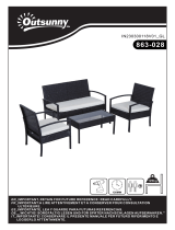
STANDARD INSTALLATION R23 RANGE
INSTALLATION TYPE SÉRIE R23
SISTEMA DO TIPO SÉRIE R23
DESCRIZIONE DESCRIPTION DESCRIPTION DESCRIPCIÓN DESCRIÇÃO
1
Automasmo R23 Automasm R23 Automasierung R23 Automasme R23 Automasmo R23 Automasmo R23
2
Centrale di comando Control unit Steuerung Centrale de commande Central de mando Central de comando
3
Seleore a chiave Key selector Schlüsseltaster Sélecteur à clé Selector de llave Selector de chave
Lampeggiante Flashing light Blinkleuchte Clignotant Luz intermitente Lampejante
Antenna Antenna Antenne Antenne Antena Antena
Fotocellula esterna External photocell Externe Lichtschranke
Cellule photoélectrique
externe
Barrera fotoeléctrica
exterior
Sensor fotoelétrico
externo
Fotocellula interna Internal photocell Interne Lichtschranke
Cellule photoélectrique
interne
Barrera fotoeléctrica
interior
Sensor fotoelétrico
exterior
Fermo meccanico in
apertura
Gate open mechani-
cal stop
Mechanische Feststellvor-
richtung beim Önen
Butée mécanique en
ouverture
Tope mecánico de
apertura
Retentor mecânico em
abertura
2MODELLE UND
EIGENSCHAFTEN MODELOS Y CARACTERÍSTICAS
MODELOS E CARACTERÍSTICAS
2x1-TX
3x1.5
4x1-RX
RG58
4x1-RX
3x1
2x1-TX
3x1.5/230 V
3x1.5
2x1.5
35 4 87
1
2
1 6
67 8

9
DIMEN
SÕES
CARACTERÍSTICAS TÉCNICAS
ALIMENTAÇÃO MOTOR
V 230 Vac 50 Hz
NENNLEISTUNG
W 200
A 1,1
% 50
14
IMPULSO N 400
TEMPERATURE DE SERVICE
TEMPERATURA DE FUNCIONAMENTO
-20°C +55°C
140
GRAU DE PROTECÇÃO
IP 43
PESO DO OPERADOR
15,5
10
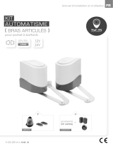
WORKING DIAGRAM
DIAGRAMA DE UTILIZAÇÃO
0 1 2 3
3,5
m
600
4
200
400
kg
160
190
355
174
14

10
A
120 80 95°
120 300 90°
140 120 100°
160 160 100°
180 200 105°
200 80 115°
200 250 105°
200 300 100°
A
120 200 90°
150 120 100°
150 400 90°
200 100 105°
200 350 90°
200 500 90°
250 350 90°
250 450 90°
80
2xØ6,5
100
46
16,7
KT218
KT208
1
2
192
KT218
KT208
1
2
258
140
200
35 3030
95
B
A
600÷800
B
A 350÷450
max 430
max 630
min 150°
max 170°
min 150°
max 170°
max
500
max
300
LT302
LT303
1
1
2
2

11
IT
VERIFICHE PRELIMINARI PRIMA DELL’INSTALLAZIONE
Vericare che la struura del cancello sia robusta, che i cardini siano
ben ingrassa e che il movimento sia uido, regolare per tua la sua corsa e
senza ari.
Prevedere sempre una bauta meccanica di arresto in apertura e chiusura ben
ssata al suolo, dotata di un elemento elasco (esempio: gomma) che ausca
l’arrivo in bauta dell’anta.
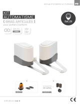
FISSAGGIO STAFFE
1. Togliere il coperchio dell’auatore R23 svitando le due vi [C].
2. Svitare la vite [D] e rimuovere il sistema di sblocco [E].
3. Svitare le 4 vi [F] e rimuovere il motore [G].
4. In funzione al modello da installare, agli spazi e agli ingombri presen in sito
e in funzione all‘angolo di apertura desiderato, posizionare la staa poste-
riore sul pilastro.
5. Fissare la staa posteriore KT208 (1) in bolla come da misure [A] e [B] di
installazione indicate nelle tabelle.
• Su pilastri in muratura ssare la staa con tasselli e vi adeguate.
• Su pilastri in ferro saldare la staa.
6. Con cancello completamente chiuso posizionare la staa anteriore KT218 (2),
rispeando le misure [A] e [B], possibilmente al centro del cancello e in corri-
spondenza di un solido traverso. Fissare la staa in bolla all’anta del cancello,
come indicato in gura.
ATTENZIONE: se si ulizza una saldatrice elerica, non saldare le stae con l‘at-
tuatore montato. Le corren di saldatura potrebbero provocare danni.
EN
PRELIMINARY CHECKS
Check that the structure of the gate is sturdy and in good condion, that
the hinges are well greased and that the gate moves throughout its enre travel
smoothly without impediment or fricon.
Always install mechanical stops in the gate open and gate closed posions, an-
chored securely to the ground and with elasc damper elements (e.g. rubber
buer) to aenuate the impact of the gate leaf against the stop.
1. Remove the cover from the R23 actuator aer loosening the two screws [C].
2. Loosen the screw [D] and remove the lock release system [E].
3. Loosen the 4 screws [F] and remove the motor [G].
4. Depending on the model installed, on the available space and any obstacles
exisng in the installaon site, and on the required angle of aperture, install
the rear bracket on the pillar.
5. Fasten the rear bracket KT208 (1) in a perfectly level posion and in accord-
ance with the installaon measurements [A] and [B] indicated in tables.
• For masonry/cement pillars, use the specic masonry brackets with suit-
able anchor bolts and screws.
• With steel pillars, weld the bracket in place.
6. With the gate fully closed, posion the front bracket KT218 (2) (respecng the
measurements [A] and [B]) in the centre of the gate if possible, and in line with
a solid crossbar. Fasten the bracket in a perfectly level posion relave to the
gate, as indicated in the gure.
IMPORTANT: if using an electric welding machine, do not weld the brackets
with the actuator installed. Electric current from the welding machine may cau-
se damage.
DE
EINLEITENDE KONTROLLEN
Sicherstellen, dass die Struktur des Tors robust ist, die Angeln gut ein-
gefeet sind und die Bewegung über den gesamten Torlauf üssig und regel-
mäßig, ohne Reibungen erfolgt. Stets einen mechanischen Anschlag in Önung
und Schließung vorsehen, der fest am Boden verankert ist und über ein elas-
sches Element (z.B.: Gummi) verfügt, das den Anschlag des Torügels dämp.
1. Durch Lösen der beiden Schrauben [C] den Deckel des Stellantriebs R23
enernen.
2. Die Schraube [D] lösen und das Entriegelungssystem [E] enernen.
3. Die 4 Schrauben [F] lösen und den Motor [G] enernen.
4. Je nach zu installierendem Modell, Raum und Platzbedarf vor Ort sowie ge-
wünschtem Önungswinkel, den hinteren Bügel auf dem Pfeiler posionie-
ren.
5. Den hinteren Bügel KT208 (1) nivelliert nach den im Tabelle angegebenen
Installaonsmaßen [A] und [B] befesgen.
• Bei gemauerten Pfeilern die für dieses Material vorgesehenen Bügel mit
geeigneten Dübeln und Schrauben verwenden.
• Bei Eisenpfeilern den Bügel anschweißen.
6. Bei ganz geschlossenem Tor den vorderen Bügel KT218 (2), unter Beachtung
der Maße [A] und [B], möglichst im Zentrum des Tors und in Höhe eines
soliden Querträgers anbringen. Den Bügel waagerecht ausgerichtet am Tor-
ügel befesgen, wie auf der Abbildung dargestellt.
ACHTUNG: Wenn man ein Elektroschweißgerät verwendet, die Bügel nicht mit
monertem Stellantrieb anschweißen. Der Schweißstrom könnte den Stellant-
rieb beschädigen.
CONTRÔLES PRÉLIMINAIRES
C
C
D
E
F
F
G
4x TE M8x10
4x M8
FR
CONTRÔLES PRÉLIMINAIRES
Vérier que la structure du portail soit robuste, que les gonds soient
bien graissés et que le mouvement soit uide et régulier sur toute la course et
sans froements.
Toujours prévoir une butée mécanique d‘arrêt en ouverture et fermeture bien
xée au sol, dotée d‘un élément élasque (exemple : caoutchouc) qui amorsse
l‘arrivée en butée du vantail.
FIXATION DES ÉTRIERS
1. Rerer le couvercle de l’aconneur R23 en dévissant les deux vis [C].
2. Dévisser la vis [D] et rerer le système de déverrouillage [E].
3. Dévisser les 4 vis [F] et rerer le moteur [G].
4. En foncon du modèle à installer, des espaces et des encombrements
présents sur place et en foncon de l‘angle d‘ouverture souhaité, placer
l‘étrier arrière sur le pilier
5. Fixer l‘étrier arrière KT208 (1) à niveau conformément aux cotes [A] et [B]
d‘installaon indiquées dans les tableau.
• Fixer l‘étrier à l‘aide de chevilles et vis appropriées sur des piliers en
maçonnerie.
• Sur les piliers en fer, souder l‘étrier.
6. Le portail enèrement fermé, placer l’étrier avant KT218 (2), en respectant les
cotes [A] et [B], si possible au centre du portail et au niveau d’une solide tra-
verse. Fixer l’étrier à niveau avec le vantail du portail, comme indiqué dans la
gure.
ATTENTION : en cas d’ulisaon d’un poste à souder électrique, ne pas souder
les étriers avec l’aconneur monté. Les courants de soudage peuvent provo-
quer des dommages.
ES
Compruebe que la estructura de la cancela sea sólida, que los goznes
estén bien engrasados y que el movimiento sea uido y regular en toda su car-
rera y no presente roces.
Prevedere sempre una bauta meccanica di arresto in apertura e chiusura ben
ssata al suolo, dotata di un elemento elasco (esempio: gomma) che ausca
l’arrivo in bauta dell’anta.
1. Rere la tapa del actuador el R23 desenroscando los dos tornillos [C].
2. Aoje el tornillo [D] y quite el sistema de desbloqueo [E].
3. Aoje los 4 tornillos [F] y quite el motor [G].
4. En función del modelo que se ha de instalar, del espacio y las dimensiones
que se encuentran in situ y en función del ángulo de apertura deseado, colo-
que el estribo trasero sobre el pilar.
5. Asegure el soporte trasero KT208 (1) nivelado horizontal y vercalmente
según las medidas [A] y [B] de montaje de las tablas.

13
1
1
3
3
3
3
3
3
3
3
4
4
5
5
6
6
4x TE M8x110
4x TE M8x110
4x M8
4x M8
10
9
15
15
13
14
4
6
1
2
3
11
12
641
7
8
5
6 9 10 15
12 13
14 11
5
7
8
M12
TTQST M12x40
TTQST M12x40
12x24x2,5
12x36x3
12x36x3
M12
TE M8x25
8x24x2
Fig. 1
Fig. 2
R23 INSTALLATO A SINISTRA
INSTALLED ON THE LEFT
R23 INSTALLATO A DESTRA
INSTALLED ON THE RIGHT

14
DSCHALTER FIJACIÓN DEL FINAL DE CARRERA FIXAÇÃO
DO FIM DE CURSO
IT
Togliere alimentazione di rete.
1. Rimuovere il coperchio del motore.
2. In base alla posizione di installazione del motore: destra (g. 1) o
sinistra (g. 2) regolare i necorsa come indicato di seguito.
• Con cancello completamente chiuso allentare la vite di ssaggio della
camma di chiusura e ruotarla manualmente in modo da avere il micro di
chiusura premuto e il micro di apertura non premuto.
• Con cancello completamente aperto allentare la vite di ssaggio e regolare
la camma di apertura in modo da avere il micro di apertura premuto e
quello di chiusura non premuto.
3. A regolazione ulmata, serrare le vi vericando che le camme lavorino libe-
ramente e senza ari.
NOTA: Qualora la regolazione non fosse suciente, svitare le vi delle camme
completamente e cambiare foro di ssaggio, scegliendo quello più adao sull’a-
nello porta camme.
EN
Disconnect from the mains power supply.
1. Remove the motor cover.
2. Depending on which side the motor is installed on, (g. 1) if installed
on right or (g. 2) if installed on le, adjust the limit switches as described as
follows.
• With the gate completely closed, loosen the screw fastening the closed
posion cam and rotate the cam so that the closed microswitch is pressed
and the open microswitch is not pressed.
• With the gate completely open, loosen the fastener screw and adjust the
open posion cam so that the open microswitch is pressed and the closed
microswitch is not pressed.
• Aer adjusng, ghten the screws and check that the cams operate smooth-
ly and without impediment.
: If the cam cannot be turned into the correct posion, undo the cam fas-
tener screws completely and move the cam onto a more suitable mounng hole
on the cam carrier ring.
DE
Die Stromversorgung unterbrechen.
1. Den Deckel des Motors enernen.
2. Je nach Installaonsposion des Motors: rechts (g. 1) oder links
(g. 2) die Endschalter wie nachstehend angegeben einstellen.
• Bei vollständig geschlossenem Tor die Befesgungsschraube des
Schließnockens lockern und ihn so von Hand drehen, dass der Mikroschal-
ter Schließer gedrückt und der Mikroschalter Öner nicht gedrückt ist.
• Bei vollständig geönetem Tor die Befesgungsschraube lockern und den
Önungsnocken so von Hand drehen, dass der Mikroschalter Öner ge-
drückt und der Mikroschalter Schließer nicht gedrückt ist.
• Nach erfolgter Einstellung, die Schrauben festziehen und prüfen, ob die
Nocken frei und reibungslos arbeiten.
HINWEIS: Falls die Einstellung nicht ausreichend ist, die Schrauben der Nocken
ganz abschrauben und die Befesgungsbohrung wechseln, indem man die bess-
er geeignete auf dem Nockenhaltering wählt.
FR
Couper l’alimentaon de réseau.
1. Rerer le carter du moteur.
2. En foncon de la posion d’installaon du moteur : droite (g. 1) ou
gauche (g. 2) régler les butées comme indiqué ci-après.
• Le portail enèrement fermé, desserrer la vis de xaon de la came de
fermeture et la tourner manuellement de manière à avoir le micro de fer-
meture enfoncé et le micro d’ouverture non enfoncé.
• Le portail enèrement ouvert, desserrer la vis de xaon et régler la came
d’ouverture de manière à avoir le micro d’ouverture enfoncé et le micro
de fermeture non enfoncé.
3. Au terme du réglage, serrer les vis en vériant que les cames fonconnent
librement et sans froements.
REMARQUE : Si le réglage ne sut pas, dévisser enèrement les vis des cames
et changer de trou de xaon en choisissant le plus adapté sur la bague porte-
cames.
ES
Desconecte la alimentación eléctrica.
1. Rere la tapa del motor y la cubierta del condensador.
2. En función de la posición de montaje del motor: derecha (g. 1) o
izquierda (g. 2) ajuste los nales de carrera, como se muestra a connu-
ación.
• Con la cancela completamente cerrada aoje el tornillo de jación de la
leva de cierre y gírela manualmente manteniendo el microinterruptor de
cierre presionado y el microinterruptor de apertura sin presionar.
• Con la cancela completamente abierta aoje el tornillo de jación y ajuste
la leva de apertura manteniendo el microinterruptor de apertura presio-
nado y el microinterruptor de cierre sin presionar.
3. Después del ajuste, apriete los tornillos y compruebe que las levas funcionan
libremente y sin fricción.
NOTA: Si el ajuste no es suciente, aoje los tornillos de las levas y cambie com-
pletamente el oricio de jación eligiendo el más adecuado en el anillo portale-
vas.
PT
Corte a alimentação de rede.
1. Rere a tampa do motor.
2. Em base à posição de instalação do motor: direita (g. 1) ou esquer-
da (g. 2) ajuste os ns de curso conforme indicado a seguir.
• Com o portão completamente fechado, afrouxe o parafuso de xação da
came de fecho e rode-o de modo a ter o micro de fecho premido e o micro
de abertura não premido.
• Com o portão completamente aberto, afrouxe o parafuso de xação e
ajuste a came de abertura de modo a ter o micro de abertura premido e o
de fecho não premido.
3. Após ter concluído o ajuste, aperte os parafusos vericando se as cames tra-
balham livremente e sem atritos.
NOTA: Caso o ajuste não seja suciente, desenrosque os parafusos dos cames
completamente e mude furo de montagem, escolhendo o mais adequado no
anel porta cames.
OPEN
CLOSE
OPEN
CLOSE
CLOSE
OPEN
OPEN
CLOSE
R23 INSTALLATO A DESTRA
INSTALLED ON THE RIGHT
R23 INSTALLATO A SINISTRA
INSTALLED ON THE LEFT
Fig. 1 Fig. 2

15
ELEKTRISCHE ANSCHLÜSSE
CONNEXIONS ÉLECTRIQUES CONEXIONES ELÉCTRICAS LIGAÇÕES ELÉCTRICAS
IT
Prima di collegare l’alimentazione elerica accertarsi che i da di targa siano risponden a quelli della rete di distribuzio-
ne elerica. Prevedere sulla rete di alimentazione un interruore/sezionatore onnipolare con distanza d’apertura dei
conta uguale o superiore a 3 mm. Vericare che a monte dell’impianto elerico vi siano un interruore dierenziale e
una protezione di sovracorrente adegua.
EN
Before connecng to electrical power, ensure that the mains power specicaons on the idencaon plate match the
mains power supply used. A switch or an omnipolar cut-o switch with a contact opening of at least 3 mm must be in-
stalled on the mains power line. Ensure that an adequate residual current circuit breaker and a suitable overcurrent
cut-out are installed ahead of the electrical installaon.
DE
Vor Anschluss der Stromversorgung ist sicherzustellen, dass die Daten des Typenschilds mit denen des Stromnetzes über-
einsmmen. Am Versorgungsnetz einen allpoligen Schalter oder Trennschalter mit Önungsabstand der Kontakte von
mindestens 3 mm einbauen. Sicherstellen, dass vor der elektrischen Anlage ein Fehlerstromschutzschalter und ein ge-
eigneter Überstromschutz vorhanden sind.
FR
Avant de brancher l’alimentaon électrique, s’assurer que les données de la plaque signaléque correspondent aux
données du réseau de distribuon électrique. Prévoir sur le réseau d’alimentaon un interrupteur ou un disposif de
coupure omnipolaire avec distance d’ouverture des contacts égale ou supérieure à 3 mm. Vérier qu’en amont de l’instal-
laon électrique il y ait un disjoncteur et une protecon contre la surintensité appropriés.
ES
Antes de conectar la alimentación eléctrica, cerciórese de que los datos de la placa correspondan a los de la red de distribución eléctrica.
Monte en la red de alimentación eléctrica un interruptor/seccionador omnipolar con una distancia de apertura de los contactos de 3 mm o superior.
Compruebe que antes de la instalación eléctrica haya un interruptor diferencial y una protección de sobrecorriente adecuados.
PT
Antes de conectar a fonte de alimentação, cerquese os dados de matrícula correspondem aos da rede de distribuição de energia. Prever na rede de alimentação um interrup-
tor/ interruptor unipolar com distância de abertura dos contatos igual ou superior a 3 mm. Vericar que, a montante da instalação elétrica, há um interruptor diferencial e uma
proteção de sobrecarga adequados.
WARTUNGSPLAN
MAINTENANCE PLAN DE MANTENIMIENTO PLANO DE MANUTENÇÃO
OPEN
CLOSE
FASE 1
COMUNE
common
FASE 2
Finecorsa chiusura
Closing limit switch
Finecorsa chiusura
Closing limit switch
Finecorsa apertura
Opening limit switch
Finecorsa apertura
Opening limit switch
OPEN
CLOSE
IT
NOTA: Per l’eventuale riparazione o sostuzione dei prodo dovranno essere u-
lizza esclusivamente ricambi originali. L’installatore deve fornire tue le informa-
zioni relave al funzionamento automaco, manuale e di emergenza della porta o
cancello motorizza, e consegnare all’ulizzatore dell’impianto le istruzioni d’uso.
L’installatore deve redigere il registro di manutenzione, nel quale dovrà indicare tu gli
interven di manutenzione ordinaria e straordinaria eeua. Eeuare le seguen ope-
razioni e veriche ogni 6 mesi, in base all’intensità di ulizzo dell’automazione.
Togliere alimentazione 230 V~ e baerie (se presen):
- Lubricare i leverismi del motoriduore.
- Lubricare il perno di rotazione anta.
- Lubricare le cerniere del cancello.
- Controllare il buono stato dei collegamen elerici.
- Controllare il serraggio delle vi di ssaggio del motoriduore.
Ridare alimentazione 230 V~, e baerie (se presen):
- Vericare le regolazioni di forza.
- Controllare il correo funzionamento di tue le funzioni di comando e le sicurezze.
- Controllare il correo funzionamento del sistema di sblocco.
EN
Only use original spare parts when repairing or replacing products.
The installer must provide the user with complete instrucon for using the motor-
ised door or gate in automac, manual and emergency modes, and must hand the
operang instrucons to the user of the installaon upon compleon.
The installer must compile the maintenance log book, in which all scheduled and unsched-
uled maintenance operaons performed must be indicated.
Disconnect the 230V~ power supply and the baeries (if installed).
- Lubricate the linkages of the gear motor.
- Lubricate the gate rotaon pin.
- Lubricate the gate hinges.
- Check the electrical connecons are in good condion.
- Make sure the gear motor xing screws are properly ghtened.
Reconnect the 230V~ power supply and replace the baeries (if installed).
- Check the force adjustments.
- Make sure all the command and safety funcons (photocells) are working properly.
- Make sure the lock release system is working properly.
DE
HINWEIS: Bei Reparaturen oder Austausch der Produkte dürfen ausschließlich Ori-
ginalersatzteile verwendet werden.
Der Installateur muss alle Informaonen zum automaschen, manuellen und Not-
Betrieb des Tors liefern und dem Benutzer der Anlage die Gebrauchsanleitung
übergeben.
Der Installateur muss das Register der Wartungsarbeiten erstellen, in dem alle dur-
chgeführten Eingrie der ordentlichen und außerordentlichen Wartung zu vermerken sind.
Die 230 V~ Stromzuführung trennen und die Baerien (falls vorhanden) entnehmen:
- Das Hebelwerk des Getriebemotors schmieren.
- Den Drehzapfen des Flügels schmieren.
- Das Scharnier des Tors schmieren.
- Den ordnungsgemäßen Zustand der elektrischen Anschlüsse kontrollieren.
- Das Anzugsmoment der Befesgungsschrauben des Getriebemotors kontrollieren.
Die 230 V~ Stromversorgung wiederherstellen und die Baerien (falls vorhanden) wieder
einsetzen:
- Die Einstellungen der Kräe prüfen.
- Die korrekte Funkonsweise aller Steuerfunkonen und der Sicherheitseinrichtungen
(Fotozellen) kontrollieren.
- Die korrekte Funkonsweise der Entriegelungsvorrichtung kontrollieren.
FR
REMARQUE : Pour l’éventuelle réparaon ou remplacement des produits, seules
des pièces de rechange originales devront être ulisées.
L’installateur doit fournir les informaons relaves au fonconnement automa-
que, manuel et d’urgence de la porte ou du portail motorisé, et remere à l’uli-
sateur de l’installaon les consignes d’ulisaon.
L’installateur doit rédiger le registre d’entreen, dans lequel il devra indiquer toutes les
intervenons d’entreen ordinaire et extraordinaire eectuées.
Couper l’alimentaon 230 V~ et des baeries (le cas échéant) :
- Lubrier les mécanismes du motoréducteur.
- Lubrier l’axe de rotaon du vantail.
- Lubrier les charnières du portail.
- Contrôler le bon état des raccordements électriques.
- Contrôler le serrage des vis de xaon du motoréducteur.
Remere l’alimentaon 230 V~ et des baeries (le cas échéant) :
- Vérier les réglages de force.
- Contrôler le bon fonconnement de toutes les foncons de commande et les sécurités
(photocellules).
- Contrôler le bon fonconnement du disposif de déverrouillage.
ES
NOTA: Ulice solo recambios originales para la reparación o la sustución de los
productos.
El instalador debe facilitar toda la información relacionada con el funcionamiento
automáco, manual y de emergencia, puerta o cancela motorizadas, y entregar al
usuario las instrucciones de uso.
El instalador deberá redactar el registro de mantenimiento, donde indicar todas las opera-
ciones de mantenimiento ordinario y extraordinario que lleva a cabo.
Desconecte la fuente de alimentación 230 V ~ y las baterías (si las hay):
- Lubrique las palancas del motorreductor.
- Lubrique el perno de rotación de la hoja.
- Lubrique las bisagras de la cancela.
- Compruebe el buen estado de las conexiones eléctricas.
- Compruebe el apriete de los tornillos de jación del motorreductor.
Desconecte la fuente de alimentación 230 V ~ y las baterías (si las hay):
- Compruebe los ajustes de fuerza.
- Compruebe el funcionamiento de todas las funciones de mando y los disposivos de
seguridad (fotocélulas).
Compruebe el funcionamiento del sistema de desbloqueo.
PT
NOTA: Para a eventual reparação ou a substuição dos produtos deverão ser uli-
zadas exclusivamente peças de reposição originais.
O instalador deve fornecer todas as informações relavas ao funcionamento au-
tomáco, manual e de emergência da porta ou do portão motorizados, e fornecer
ao ulizador do sistema as instruções de operação.
O instalador deve elaborar o registo de manutenção, que deve indicar todas as operações
de manutenção ordinária e extraordinária realizadas.
Desligue a alimentação 230 V~ e as baterias (se presentes):
- Lubrique os acoplamentos do motor redutor.
- Lubrique o pino de rotação da pornhola.
- Lubrique as dobradiças do portão.
- Verique o bom estado das ligações elétricas.
- Verique o aperto dos parafusos de xação do motor redutor.
Volte a ligar a alimentação 230 V~ e as baterias (se presentes):
- Verique as congurações de força.
- Verique o funcionamento correto de todas as funções de controlo e os disposivos de
segurança (fotocélulas).
- Verique o funcionamento correto do sistema de desbloqueio.
/